EP0675794B1 - Moule pour coulage par injection a phases de chaufage et de refroidissement - Google Patents
Moule pour coulage par injection a phases de chaufage et de refroidissement Download PDFInfo
- Publication number
- EP0675794B1 EP0675794B1 EP94903457A EP94903457A EP0675794B1 EP 0675794 B1 EP0675794 B1 EP 0675794B1 EP 94903457 A EP94903457 A EP 94903457A EP 94903457 A EP94903457 A EP 94903457A EP 0675794 B1 EP0675794 B1 EP 0675794B1
- Authority
- EP
- European Patent Office
- Prior art keywords
- temperature
- mold
- thermoplastic
- inserts
- heat transfer
- Prior art date
- Legal status (The legal status is an assumption and is not a legal conclusion. Google has not performed a legal analysis and makes no representation as to the accuracy of the status listed.)
- Expired - Lifetime
Links
Images


Classifications
-
- B—PERFORMING OPERATIONS; TRANSPORTING
- B29—WORKING OF PLASTICS; WORKING OF SUBSTANCES IN A PLASTIC STATE IN GENERAL
- B29D—PRODUCING PARTICULAR ARTICLES FROM PLASTICS OR FROM SUBSTANCES IN A PLASTIC STATE
- B29D17/00—Producing carriers of records containing fine grooves or impressions, e.g. disc records for needle playback, cylinder records; Producing record discs from master stencils
- B29D17/005—Producing optically read record carriers, e.g. optical discs
-
- B—PERFORMING OPERATIONS; TRANSPORTING
- B29—WORKING OF PLASTICS; WORKING OF SUBSTANCES IN A PLASTIC STATE IN GENERAL
- B29C—SHAPING OR JOINING OF PLASTICS; SHAPING OF MATERIAL IN A PLASTIC STATE, NOT OTHERWISE PROVIDED FOR; AFTER-TREATMENT OF THE SHAPED PRODUCTS, e.g. REPAIRING
- B29C45/00—Injection moulding, i.e. forcing the required volume of moulding material through a nozzle into a closed mould; Apparatus therefor
- B29C45/17—Component parts, details or accessories; Auxiliary operations
- B29C45/26—Moulds
- B29C45/37—Mould cavity walls, i.e. the inner surface forming the mould cavity, e.g. linings
-
- B—PERFORMING OPERATIONS; TRANSPORTING
- B29—WORKING OF PLASTICS; WORKING OF SUBSTANCES IN A PLASTIC STATE IN GENERAL
- B29C—SHAPING OR JOINING OF PLASTICS; SHAPING OF MATERIAL IN A PLASTIC STATE, NOT OTHERWISE PROVIDED FOR; AFTER-TREATMENT OF THE SHAPED PRODUCTS, e.g. REPAIRING
- B29C45/00—Injection moulding, i.e. forcing the required volume of moulding material through a nozzle into a closed mould; Apparatus therefor
- B29C45/17—Component parts, details or accessories; Auxiliary operations
- B29C45/72—Heating or cooling
- B29C45/73—Heating or cooling of the mould
- B29C45/7306—Control circuits therefor
-
- B—PERFORMING OPERATIONS; TRANSPORTING
- B29—WORKING OF PLASTICS; WORKING OF SUBSTANCES IN A PLASTIC STATE IN GENERAL
- B29C—SHAPING OR JOINING OF PLASTICS; SHAPING OF MATERIAL IN A PLASTIC STATE, NOT OTHERWISE PROVIDED FOR; AFTER-TREATMENT OF THE SHAPED PRODUCTS, e.g. REPAIRING
- B29C45/00—Injection moulding, i.e. forcing the required volume of moulding material through a nozzle into a closed mould; Apparatus therefor
- B29C45/17—Component parts, details or accessories; Auxiliary operations
- B29C45/76—Measuring, controlling or regulating
- B29C45/78—Measuring, controlling or regulating of temperature
-
- B—PERFORMING OPERATIONS; TRANSPORTING
- B29—WORKING OF PLASTICS; WORKING OF SUBSTANCES IN A PLASTIC STATE IN GENERAL
- B29C—SHAPING OR JOINING OF PLASTICS; SHAPING OF MATERIAL IN A PLASTIC STATE, NOT OTHERWISE PROVIDED FOR; AFTER-TREATMENT OF THE SHAPED PRODUCTS, e.g. REPAIRING
- B29C45/00—Injection moulding, i.e. forcing the required volume of moulding material through a nozzle into a closed mould; Apparatus therefor
- B29C45/17—Component parts, details or accessories; Auxiliary operations
- B29C45/72—Heating or cooling
- B29C45/73—Heating or cooling of the mould
- B29C2045/7356—Heating or cooling of the mould the temperature of the mould being near or higher than the melting temperature or glass transition temperature of the moulding material
Definitions
- the present invention relates to an improved method and apparatus for injection molding thermoplastics with better surface replication and precision , by starting each molding cycle with mold surfaces heated to retard melt Solidification before starting injection , then cooling after the mold is filled to solidify the thermoplastic before opening the mold .
- Yang (U.S. patent 4,390,485 issued June 28, 1983) teaches to "quickly heat a mold cavity surface . . . just prior to the injection of a foamable plastic resin " . . . using thin metal surface sheets heated by electrical resistance at low voltage in an otherwise conventional mold and molding sequence.
- Hendry U.S. 4,390,486 issued June 28, 1983 is another approach to preheating mold cavity surfaces in order to create a resin-rich smooth surfaced foam molding process. Hendry uses a condensing vapor, such as steam, introduced into the mold before injection starts, in order to warm the surfaces, then tries to remove the condensing vapor before injection starts. Obviously, any residual condensate acts as an impurity at the molded surface, which would quickly produce a cosmetic flaw or even worse, in the case where a water -sensitive plastic such as polycarbonate, PET, or nylon would be brought in contact with any residual moisture, which would then cause instantaneously the well - known "silver streak" type of cosmetic flaws.
- a condensing vapor such as steam
- Depcik U.S. 5,061,415 issued October 29, 1991 teaches use of localized heating of only a portion of the mold cavity by means of high frequency electromagnetic field and application of pressure in the critical region in order to prevent what he called “sunk spots” (which are believed to be what is commonly called “sink marks”).
- Suh U.S. 4,338,068 issued July 6, 1982 and U.S. 4,548,773 issued October 22, 1985.
- Suh recognizes that , for reproducible precise dimensions of the molded part, uniform shrinkage of the molded plastic is essential. Therefore , in a typical thermoplastic molding of cross-sectionally non-uniform wall thickness, there will inevitably be non-uniform shrinkages unless these localized regions of the mold have differential heat transfer capabilities.
- Suh provides this capability of localized differential thermal conductence by means of heat pipes installed at those stragegic points.
- Suh also teaches use of a thin mold face which can be electrically heated by means of incorporating electrical resistence wires within an electroform.
- Wada (U.S. 4,340,551 issued July 20, 1982) seeks to heat only the mold cavity surfaces, to the extent possible, to a temperature above the heat distortion of the thermoplastic resin composition, in order to again create a resin-rich layer when molding a filled or fiberglass reinforced thermoplastic.
- Wada uses electrical induction heating, supplied by means of a double-faced removable block (heated inductively from within) having on each of the 2 faces side a mating contour which can mate with the contour of the opposing inner facing mold cavity surfaces. This block can be moved in and out of the mold from within the parting line on each molding cycle.
- Wada's alternative embodiment is to incorporate the induction heating element (B and B' as shown in Figure 4) directly behind the mold cavity element which forms the outward facing surface on either side of the parting line.
- C and C' are insulation layers made from non-magnetic metals such as the alloys of copper and aluminum, which are not responsive to high frequency induction heating, in order to thereby minimize dissipation of this energy into the mold as a whole.
- these metals are "dead” with respect to energy flux of induction heating, they would be of course among the highest thermally conductive metals and are therefore the exact opposite of isolating the rest of the mold from thermal conduction.
- Cooling means for circulating coolant within Wada molds are not shown in any of the drawings, but are implied in the text, and in example 1 Wada states that during induction heatup phase of the molding cycle, circulation of the coolant is stopped.
- Wada's preferred embodiment is that the heating efficiency is directly proportional to the surface area of contact between the induction heating element (inserted at the open parting line, then clamped together between the mold halves) and the opposing mold cavity faces that are to be heated up before injection starts. These opposing mold cavity faces are , in turn, inevitably scratched and marred by this contact . The greater the clamping force applied (to bring the surfaces into intimate contact), the worse the surface damage. Any slight misalignment of the A and B moldhalves (i.e. not exactly co-axial) will aggrevate this damage , if the cavities are contoured (as would be the case with optical lenses).
- Wada is apparently being used only for opaque (non-optical) moldings, and especially suited for textured moldings and glass-fiber-filled plastics. See enclosed Asahi publications and June 1992 Modern Plastics Magazine article (p.21). There is no support for any belief that Wada has been used successfully within the relevant field of optically transparent thermoplastics injection molded into optical disks for information storage and holographic imaging , and/or optical lenses and reflective optical elements.
- Waters (U.S. 4,623,497 issued November 18, 1986) provides a passive mold cooling and heating method which locates a heating OR a cooling fluid which is capable of phase change into vapor and out of vapor by subsequent condensation.
- This fluid reservoir is located below the height of the mold within which circulation is to take place, so that during heat up phase, the fluid is turned into vapor and rises throughout the channels provided in the mold. Then, after condensing, the vapor returns by gravity.
- Waters' main advantage appears to be that it is a passive system, not requiring large volumes of pumped liquids in circulation to achieve its result.
- Waters teach an advantage to preheat the mold surfaces above a solidification or heat distortion temperature of the plastic, then change to cooling conditions for rapid heat removal within the same injection molding cycle.
- Waters is intended to be used in many forms of thermoplastic and thermoset molding, including injection molding, blow molding, rotational molding, compression molding, reaction injection molding, etc. The latter two are predominantly employed with a thermoset , crosslinkable plastics, and in those cases, the purpose of circulating heat transfer fluid is to heat the mold, not to dissipate the heat of injected molten thermoplastic.
- Waters does not teach alternating within the same molding cycle a heating phase and a cooling phase; he concentrates rather on the simplification of the fluid heat transfer media conveyance system.
- Steinbiechler (U.S. 4,902,454 issued Februrary 20, 1990) provided for a intermittent actuation of certain valving, preferably in response to temperature sensors mounted within the connecting lines for which circulating coolant flows into and out of a mold temperature controlling unit on its way into and out of the molds.
- Preferred embodiment also employs an additional temperature sensor mounted within the mold itself.
- the purpose of this invention appears to be to optimize the uniformity of mold thermal control within a tolerance band during "steady state" production injection molding of thermoplastics. That is, once startup phases are ended, and production operations are implemented, the objective is to minimize mold temperature excursions by means of opening and closing the valve sets under a computer controlled sequence. It is not the intention of Steinbiechler to warm the mold surfaces above solidification temperatures before injection and subsequently to convert to a cooling phase until solidification of the filled plastic is achieved.
- the burst of cold (substantially below the desired mold temperature setpoint) fluid is injected only after the temperature sensor sensed that the mold is now filled with hot molten plastic .
- Wieder does not teach preheating the mold on each cycle to a temperature above solidification temperatures of the plastic nor that any benefit would be achieved thereby.
- U.S. patent No. 4,963,312 relates to an apparatus and method for molding plastic materials.
- the apparatus comprising a mold cavity formed by two thinwalled members inserted into mold halves. Each mold half is provided with a separate circulation system for a liquid heat carrier.
- the circulation system is connected with a heating device and a cooling device provided with suitable control valves.
- Said thinwalled members forming the mold cavity do not comprise any metallic members in the back.
- the thinwalled members are only supported and reinforced, to counter possible deformation, by the liquid heat carrier within the circulation system and shut-off from the heating device.
- U.S. patent No. 4,793,953 relates to a special mold cavity member used in high-pressure injection and compression molds for forming optical thermoplastics.
- the mold comprises:
- the mold cavity member is of seamlsess, monolithic construction comprising beryllium-copper substrate integrally joined with a nickel plated face.
- the present invention overcomes the problems of poor mold surface replication by the molded thermoplastic article and , more specifically , to be able to maximize microreplication of the finest surface detail and contour onto an optical-grade thermoplastic molded product such as optical lenses, information bearing optical disks, holographic disks of reflective and/or transmissive optics, precision molded plastic mirrors and/or refractive optical elements with a light bending function.
- an optical-grade thermoplastic molded product such as optical lenses, information bearing optical disks, holographic disks of reflective and/or transmissive optics, precision molded plastic mirrors and/or refractive optical elements with a light bending function.
- Such fidelity of the molded part to the molding surface is achieved by means of heating the mold cavity part forming surfaces at least above a characteristic solid-liquid phase-change temperature which is characteristic of the thermoplastic polymer. Since the most desirable of optically-clear thermoplastic polymers are amorphous in nature (especially , polycarbonate and acrylic), the preferred setpoint could be the glass transition temperature (Tg) . For crystalline thermoplastic polymers, another melt-state temperature would be its melting point (Tm).
- the preferred setpoint temperature would be sufficiently high so that the thermoplastic being molded is not form stable at any higher temperatures, then after the mold cavity has at least been completely filled by the molten thermoplastic and before the mold is opened at the parting line, mold surface temperature is dropped to below the Tg or Tm of that thermoplastic material. Reduction of "knitlines” and “weld lines” is another benefit.
- the mold surface temperature is maintained above Tg or Tm until the mold cavity is not only filled with melt but is sufficiently pressurized to reach a peak value for melt pressure as measured within the mold cavity.
- This preferred embodiment retards solidification of the plastic onto the mold surfaces at least until the maximum packing pressures withing the cavity has been attained, thereby forcing a still-mobile polymer molecule against the micro detail of the partforming surfaces of the mold cavity construction.
- Retarded solidification during mold cavity filling also minimizes the well-known problem of high melt pressure near the gate and much lower melt pressure near the end-of-fill cavity wall ; this "hydraulic melt pressure drop" incurred during conventional injection filling causes a corresponding difference in volumetric % shrinkage and resulting mechanical inaccuracies and warpages.
- the preferred embodiment is especially important in achieving high information carrying capacity and accuracies in optical disks and holographics disks, as well as optical lenses and other optical devices.
- the present invention preferrably employs two greatly different temperature streams of high heat transfer fluids, with one temperature being very hot relative to the desired setpoint for the molding surface temperature in the mold, and the other stream being very substantially much cooler than the desired setpoint of the mold surface temperature after it has been completely filled and packed by the molten thermoplastic.
- a temperature differential is at least 20 degrees C (38 degrees F) but is much more advantageously 50-75 degrees C, in order to provide maximum "thermo driving force" to achieve maximal heat transfer rates.
- the present invention employs within each molding cycle a heating phase and a cooling phase when viewed from the perspective of the mold cavity surface .
- the mold surfaces are warmed to minimize viscoelastic skinning as the thermoplastic meltfront flows from the gate outward.
- the molding surface temperature is deliberately reduced to maximize rate of heat removal out of the plastic, so as to cause rapid Solidification and thereby minimize total molding cycle time. This is brought about after a predetermined time (typically, measured from start of "mold closed” , as sensed by limit switch 12 of Fig. 1) expires , causing a transfer from a "heating phase” to a "cooling phase" within each individual molding cycle.
- the present invention In order to start the molding cycle at an optimally hot mold surface temperature and subsequently to drop rapidly that mold surface temperature to quicken solidification after a predetermined point in the molding cycle is reached, and thereby to minimize total molding cycle time while also maximizing molding productivity and output quality, the present invention necessarily must consider mold materials construction which have relatively good thermal conductivity and heat transfer coefficients, as well as thermal diffusivity (i.e., to minimize point-to-point temperature non-uniformities within the molding surface). Certain tool steels, for example, are substantially better in heat transfer than others; high alloy content steels such as stainless steels would NOT be Preferred.
- These preferred molds for optical thermoplastic high pressure molding combine the high surface polishability and mechanical damage resistance of electroplated nickel or chromium at the outward face of the mold cavity insert with a high conductivity substrate metal such as low alloy beryllium copper (typically 2% or less of beryllium, and 98% of more copper) or similar copper alloys, although conceivably other well known high conductivity metals such as aluminum alloys. (Similarly , precious metals such as silver and gold could conceivably be functional equivalents but too soft and too expensive).
- a high conductivity substrate metal such as low alloy beryllium copper (typically 2% or less of beryllium, and 98% of more copper) or similar copper alloys, although conceivably other well known high conductivity metals such as aluminum alloys.
- precious metals such as silver and gold could conceivably be functional equivalents but too soft and too expensive).
- a compressive yield strength of at least 344733 x 10 3 Nm -2 (50,000 psi) is required for satisfactory injection mold cavity inserts , and 551573 - 689467 x 10 3 Nm -2 (80,000-100,000 psi) is preferred) and thermodynamic properties of the substrate, a resulting monolithic mold insert well suited for operating the present invention process sequence is obtained.
- the injection mold (1) is shown in cross-section view. On each injection molding cycle, the mold is opened and closed along a parting line (16) by an injection molding machine (not shown). A mold cavity (13) is formed between mold cavity inserts (6) on either side of the parting line (16) when the mold is in a closed position.
- These mold cavity inserts are, in the case of optical lenses and/or disks, typically highly lapped and polished surfaces or, alternatively, at least one of the molding surfaces may be fitted with a thin nickel electroform which then acts as a partforming surface onto which the molded plastic will replicate itself.
- Such nickel electroform “stampers” are typically employed in optical disk molds, which may thereby contain a changeable information content, directory and formatting information, or other precision surface detail such as would be the case with a holographic array.
- the materials of construction of the mold cavity insert (6) are of sufficient mechanical load bearing and desirably of very high thermal conductivity to be suitable for rapid thermodynamic change, which is necessary if a minimal molding total cycle time is to be attained.
- copper based high strength mold alloy materials are preferred, and a most preferred embodiment would be use of Applicants U.S. 4,793,953 herein incorporated by reference, or functional equivalence thereof.
- the mold cavity insert is preferably fitted directly with heat transfer fluid circulating channels, but within a single monolithic piece of high conductivity metal. However, a less preferred embodiment would place a high conductivity mold element into an assembly joined mechanically or adhesively to a backing plate wherein the channels for circulating heat transfer fluid could be housed.
- the mold cavity inserts are mechanically supported and housed within a stationary moldhalf (4) and a moveable moldhalf (5). Note that for optimum results it is desired to create dead air space , to the extent possible without giving poor mechanical rigidity/support to the mold assembly, between the mold cavity insert (6) and its supporting mold half (4, 5) by means of thermal isolation "dead air pockets" (15) to create a desired "thermopane” effect to as much of the total surface area at the juncture of mold cavity insert (6) and the supporting mold structure mold half (4, 5).
- An alternate but less preferred embodiment not shown in Fig. 1 has NOT located the heat transfer fluid circulation channels within the opposing mold cavity inserts (6) , but rather within one or more support plates having a mating-contoured-surface onto which opposing mold cavity inserts (6) can be removably mounted (for easier changeover) , whereby intimate thermal contact is maintained therebetween.
- Such alternate but less preferred embodiment will generally have Slower heat transfer and poorer thermal diffusivity, of course .
- the fluid control unit (2) on the left hand side of the center line we see the "hot side" (which is activated during the heating phase of each injection molding cycle) , including a heat transfer fluid reservoir (22) being maintained at a higher fluid temperature than a maximum surface temperature of the mold inserts, plumbed with and outlet line which passes through a pump (20) in turn plumbed with 3 valves:
- the reservoir is heated by means of heating element (21), which operates under the electronic control of the process control unit through wire (3) through wire (50) (note temperature sensor (25) connected by control wire (50) to process control unit (3).)
- a heat exchanger (36) is operated under the control valve (37), to either increase, reduce, or eliminate entirely cooling water flow which acts to bring down the fluid temperature within reservoir (32), under the control of process control unit (3) through cooling water supply line (49).
- pump (30) feeds heat transfer fluid through check valve (27) into supply lines (7).
- check valve (27) As shown in Figure 1, the mold is in the heating phase and not in the cooling phase, therefore contol valve (28) is shown in the open position, wherein the heat transfer fluid is diverted away from supply line (7) and is dumped back into the reservoir.
- control valve (28) is wired by control wire (50) into the process control unit, as is also the fluid return line with temperature sensor (33) (23 for the hot side).
- control valve (34) When control valve (34) is shown in the closed Position, return line (8) feeds heat transfer fluid coming from the mold into the hot side through its control valve (24) (shown in the open position) and not into the cold side, since control valve (34) is shown in its closed position.
- Control valves (24) and (34) are wired by control wire (50) to the process control unit (3), and work in opposition to each other.
- Indicator light (41) is shown lit up, which means that heating is going on at this time (similarly, indicator light (45) is shown not lit up, which means that cooling is not being done at this time).
- Temperature sensor (25) provides the heat transfer fluid temperature within the hot side reservoir, and similarly temperature sensor (35) provides the heat transfer fluid temperature within the cold side reservoir (32).
- Settable temperature (38) for the fluid in the hot side reservoir (22) is shown, in this example, at 227°C (430 degrees F).
- Cavity insert temperature sensor (10) could be any conventional thermocouple (Type J , Type K, etc) but is preferably a faster-responding (0.001 second or less) thermister. Sensor (10) should be mounted within the mold cavity insert in a position very close to the partforming surfaces to be wetted by the molten polymer (about (0.100") 2.5mm setback distance is recommended). Sensor mounting can be any of the following ; surface mounting , bayonet lock, magnetic probe ; removable or permanent.
- Settable transfer temperature (40) is shown here at 165,5°C (330 degrees F).
- the process control unit (3) sends a signal through control wire (50) to flow return control valve (24) to close , and valve (34) is opened to divert the return flow of heat transfer fluid into cold side reservoir (32) .
- the setting value shown is eight seconds. That means that for eight second after start of injection, control valve (18) is closed and thus, after the timer exceeds this settable time delay value, then control valve (18) opens and bypasses heat transfer fluid away from supply line (7) back into hot side reservoir (22), thus bypassing the mold.
- Actual mold cavity temperature sensed by sensor (10) is displayed in temperature reading (47) (in this example, shown at 380 degrees F.).
- reservoir temperature settable value (42) shows the desired reservoir temperature (in this example 150 degrees F.).
- the process control unit increases the flow rate through heat exchanger valve (37) to increase the rate of heat removal out of reservoir (32).
- Cooling mold temperature value (43) can be set for determining when to open the mold and eject the part, at a point where (47) is sufficiently below Tg for the plastic's temperature (not easily directly measured) to be shape stable ; shown here in this polycarbonate optical disk example at 93,3°C (200 degrees F).
- this is substantially lower than the "control band" range of mold & coolant temperatures desired in conventional optical disk molding , which chooses a mold & coolant temperature between 115,5-129,5°C (240-265 F), and once set, the conventional optical disk molding process attempts to maintain this set value + or -2°C (5 degrees F) throughout the whole molding cycle , wherein typically best optical disk properties are obtained by these conventional processes and apparatus employing only one fluid reservoir operating at only one temperature setpoint throughout each molding cycle.
- Settable temperature value for onset of transfer from return line (8) fluid back to reservoir for the temperature sensor (33) shows a value of 137,7°C (280 degrees F).
- control valve (34) is closed and will not permit returning fluid to enter.
- the limit switch (12) signalling mold opening can be used to trigger start of heating phase, while the molded part is being ejected and the mold is again closing. (Even before actual mold opening motion trips the limit switch , it may be desirable to start heating phase BEFORE clamp decompression is started). As mold surface temperature rises up to the required minimum setpoint, heating continues, then once the desired setpoint is reached, injection can start. Sometime after the injection is ended and packing has commenced, the mold surface temperature may be allowed to fall without reducing the surface replication and quality of the molded plastic part.
- the mold cavity surface temperature which is seen by the plastic ; as long as it remains sufficiently high so that the polymer molecules are not prematurely set in place near the mold surfaces, then high fidelity replication can occur.
- the settable value for start of injection is substantially above Tg and is preferable maintained there sufficiently long to assure peak cavity melt pressures have at least been attained before mold surface temperature is allowed to drop quickly by means of onset of pumping cold side heat transfer fluids. Once active cooling is started, the mold surface temperature drops quite quickly, due to high conductivity materials and thermal isolation away from the thermal-cycling mold cavity inserts, and good proximity of the flowing coolant to the molding surfaces wetted by the molten plastic polymer.
- Faster cooling rates can be forced by dropping drastically (i.e. by at least 50 C) this mold coolant inlet temperature AFTER melt filling of the mold cavity has taken place.
- These alternative process embodiment steps do drive fast cooling by having a "cold side” reservoir fluid temperature greatly below (at least 50 C ; more preferrably, about 100 C) that of the "hot side " reservoir fluid temperature .
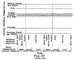
- Figure 2C shows a conventional "prior art" process sequence diagram note that actual cavity surface temperature never reaches Tg or Tm and flucuates between a lower temperature during cooling phase and a warmer temperature when the mold is being heated by the hot plastic.
- the important thing to note is that the transfer fluid temperature is deliberately maintained substantially constant throughout each injection molding cycle individually. This of course is in contrast to the present invention, which exceeds the Tg temperature at the time when injection is to start, then switches over to a much lower temperature heat transfer fluid during the actively cooling stages.
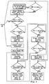
- FIG. 3 shows the process flow sheet.
- the injection molding machine is in "manual mode", with valves (18), (24) and (28) open and (34) closed.
- the injection molding machine is switched over to "automatic cycle", as shown at the top of the page.
- the heating cycle is started at least as soon as the mold is opened (as sensed by limit switch sensor (12)), and heating is started by closing control valve (18).
- temperatures (25) and temperatures (35) are within the set limits, and the actual mold surface temperature (T10) at least equals if not exceeds the settable value (39) inject, then injection is permitted to start.
- heating continues until the setpoints are reached (it is possible to add a timer which would sound an audible alarm if an abnormally long time interval has passed due to some malfunction).
- the next step is to close the heating circuit opening control valve (18), to stop flow from the "hotside " reservoir into the mold through supply lines (7) . This is done as soon as injection has started, or could alternatively be delayed by some predetermined way .
- the heating circuit is essentially closed simultaneously to the start of injection, in order to minimize total cycle time, but a longer heating phase could be run without harm to quality of the molded plastic, if one is willing to reduce output quantity with this longer total molding cycle time.
- the hold timer (48) is started and after that settable value for time is attained, then start of the cooling phase is initiated by closing valve (28).
- Fig. 3 shows these steps in a sequential, serial order , but it would be obvious to those skilled in the art to minimize cycle time by performing concurrently (i.e. in parallel) those steps which are not specifically contingent upon an outcome or measurement preceeding it.
- Transfer of heat transfer fluid from the return line (8) depends on whether sensed temperature from sensor (23) reads less than the heating transfer temperature value (40). If not, then cooling is continued as before. If so, then the return heat transfer fluid is diverted from the hot to the cold side reservoir by opening control (34) and closing control valve (24). Next, if the actual mold surface temperature T10 is less than the prescribed value for cooling setpoint (43), then move ahead to close the cooling circuit by opening control valve (28). If T10 is less than cooling setpoint (43), then continue through previous step. When T10 is greater than cooling setpoint (43), then go back to start the cooling circuit by closing valve (28) again. When that happens, in parallel to it , the mold is opened as sensed by limit switch (12), then the next step starts .
- Recycle loop checks to see that the injection molding machine is still in automatic mode , then closes valve (18) to start heating again . Only when sensed temperature from sensor (33) is greater than the settable value for cooling transfer (44), then the heat transfer fluid from return line (8) is diverted away from the cold side reservoir (32) and over to hot side reservoir (22) by opening control valve (24) and closing control valve (34).
Landscapes
- Engineering & Computer Science (AREA)
- Mechanical Engineering (AREA)
- Manufacturing & Machinery (AREA)
- Moulds For Moulding Plastics Or The Like (AREA)
- Turbine Rotor Nozzle Sealing (AREA)
Abstract
Claims (10)
- Procédé de moulage par injection d'articles thermoplastiques dans un moule d'injection (1) ayant au moins une cavité de moule (13) formée entre des éléments rapportés opposés (6) constitués d'un matériau à conductivité thermique élevée ayant au moins une résistance limite en compression d'au moins 344733 × 103 Nm-2 (50000 psi), lesdits éléments rapportés (6) étant maintenus en contact de conduction thermique avec un fluide de transfert de chaleur circulant dans des canaux pénétrant dans le moule d'injection et sortant de celui-ci par l'intermédiaire de lignes d'alimentation (7) et de lignes de retour (8) plombées sur une unité de commande de fluide ayant au moins deux réservoirs de fluide de transfert de chaleur (22, 32) chauffés et refroidis sous la commande d'une unité de commande de traitement électronique (3), au moins un réservoir côté chaud (22) étant maintenu à une température de fluide plus élevée qu'une température de surface maximum desdits éléments rapportés (6), et au moins un réservoir côté froid (32) étant maintenu à une température de fluide inférieure à une température de surface minimum desdits éléments rapportés (6), ladite température de surface minimum étant inférieure à une température au niveau de laquelle le thermoplastique est un solide de forme stable, comportant les étapes consistant à :a) chauffer de manière pratiquement uniforme des surfaces formant des parties opposées desdits éléments rapportés (6) par ladite circulation de fluide à partir dudit réservoir côté chaud (22) et maintenir ouverte une ligne de retour (8) vers ledit réservoir côté chaud (22) au moins jusqu'à ce que l'injection soit terminée et jusqu'à ce qu'une température de moule réelle telle que mesurée par un détecteur de température (10) monté dans lesdits éléments rapportés (6) lise au moins une température de point de réglage choisi pour retarder la vitesse de solidification dudit thermoplastique, de telle sorte que ladite température de moule réelle telle que mesurée par un détecteur de température (10) monté dans lesdits éléments rapportés (6) est toujours nettement inférieure à ladite température de fluide circulant dans le réservoir côté chaud ;b) injecter du thermoplastique fondu dans ladite cavité de moule (13) formée dans ledit moule d'injection (1), alors que ladite température de moule réelle est au moins égale à ladite température de point de réglage choisi pour retarder la solidification au moins jusqu'à ce que la cavité de moule (13) ait été complètement remplie dudit thermoplastique fondu, et maintenir ouverte une ligne de retour (8) vers ledit réservoir côté chaud (22) pour assurer un écoulement libre du fluide de transfert de chaleur en dehors dudit moule d'injection (1) au moins jusqu'à ce que l'injection soit terminée ;c) transférer d'une phase de chauffage vers une phase de refroidissement en stoppant l'écoulement de fluide de transfert de chaleur à partir du réservoir côté chaud (22) et en commençant l'écoulement du fluide de transfert de chaleur alimenté à partir du réservoir côté froid (32) ;d) refroidir pratiquement uniformément le moule jusqu'à ce que ladite température de moule réelle soit inférieure à la température au niveau de laquelle le thermoplastique a une forme solide stable, et ladite température de moule réelle telle que mesurée par un détecteur de temperature (10) monté dans lesdits éléments rapportés (6) étant toujours nettement plus grande que ladite température de fluide circulant dans le réservoir côté froid ;e) ouvrir le moule (1) le long d'une ligne de séparation (16) et enlever le produit thermoplastique moulé et transférer à partir d'une phase de refroidissement vers une phase de chauffage en stoppant l'écoulement du fluide de transfert de chaleur provenant du réservoir côté froid (32) et en commençant l'écoulement à partir du réservoir côté chaud (22), en préparation du début du prochain cycle de moulage par injection.
- Procédé selon la revendication 1, dans lequel ledit thermoplastique est amorphe, ledit point de réglage choisi pour retarder la vitesse de solidification est au moins égal à la température de transition vitreuse dudit thermoplastique, et ladite température au niveau de laquelle le thermoplastique a une forme solide stable est la température de transition vitreuse dudit thermoplastique amorphe.
- Procédé selon la revendication 1, dans lequel ledit thermoplastique est amorphe, ledit point de réglage choisi pour retarder la vitesse de solidification est au moins de 10 degrés C en dessous de la température de transition vitreuse dudit thermoplastique, et ladite température au niveau de laquelle le thermoplastique a une forme solide stable est la température de transition vitreuse dudit thermoplastique amorphe.
- Procédé selon la revendication 1, dans lequel ledit thermoplastique est pratiquement cristallin, ledit point de réglage choisi pour retarder la vitesse de solidification est au moins égal à la température de point de filsion dudit thermoplastique et ladite température au niveau de laquelle le thermoplastique a une forme solide stable est la température de point de fusion dudit thermoplastique cristallin.
- Procédé selon la revendication 1, dans lequel ladite température de moule réelle est au moins égale à un point de réglage prédéterminé choisi pour retarder la vitesse de solidification, jusqu'à ce que la cavité de moule ait été complètement remplie dudit thermoplastique fondu et est aussi de plus mise sous pression à un niveau voulu de pression de fusion dans ladite cavité de moule (13).
- Procédé selon la revendication 1, dans lequel le thermoplastique est amorphe, le point de réglage choisi pour retarder la vitesse de solidification est au moins égal à la température de transition vitreuse dudit thermoplastique, et ladite température au niveau de laquelle le thermoplastique a une forme solide stable est la température de transition vitreuse dudit thermoplastique amorphe, et la température du fluide de transfert de chaleur alimenté par le réservoir côté chaud est au moins de 25 degrés centigrade plus élevée que la température de transirion vitreuse du thermoplastique,
dans l'étape b, la cavité de moule (13) qui a été complètement remplie de thermoplastique fondu, est aussi de plus mise sous pression à un niveau voulu de pression de fusion dans ladite cavité de moule (13), et
dans l'étape c, la température du fluide de transfert est au moins 25 degrés centigrade inférieure à la température de transition vitreuse du thermoplastique. - Dispositif pour le moulage par injection d'articles thermoplastiques, comportant :a) un moule d'injection (1) ayant au moins une cavité de moule (13) formée entre des éléments rapportés opposés (6), au moins un détecteur de température (10) monté dans lesdits éléments rapportés, lesdits éléments rapportés (6) étant fabriqués à partir d'un matériau ayant une résistance limite en compression d'au moins 344733 × 103 Nm-2 (50000 psi) de manière à résister à la déformation par les pressions de moulage par injection, ledit matériau étant sélectionné à partir d'acier pour outils faiblement allié ou d'alliages de cuivre ou d'alliages d'aluminium, lesdits éléments rapportés (6) sont chacun en contact thermiquement conducteur avec au moins un fluide de transfert de chaleur circulant dans un canal pénétrant dans le moule d'injection et sortant de celui-ci par une ligne d'alimentation (7) et une ligne de retour (8) ;b) une unité de commande de fluide (2) ayant au moins deux réservoirs de fluide de transfert de chaleur (22, 32) en communication de fluide avec le moule d'injection (1) par lesdites lignes d'alimentation (7) et lesdites lignes de retour (8), des moyens formant vanne de commande pour ouvrir ou fermer ladite ligne d'alimentation (7) et ladite ligne de retour (8) sous la commande d'une unité de commande de traitement électronique (3), à l'aide d'au moins un réservoir côté chaud (22) ayant une température de fluide plus élevée qu'une température de surface maximum desdits éléments rapportés (6), et au moins un réservoir côté froid (32) ayant une température de fluide inférieure à la température de surface minimum desdits éléments rapportés (6), lesdits éléments rapportés (6) étant pratiquement chauffés ou refroidis uniformément avec des différences de température point à point minimales ;c) l'unité de commande de traitement électronique (3) est capable de recevoir les lectures de température provenant dudit au moins un détecteur de température (10) monté dans au moins desdits éléments rapportés (6) et provenant de tout détecteur de température (23, 26 ; 33, 35) agencé dans lesdites lignes d'alimentation (7) et lignes de retour (8) et les réservoirs (22, 32), et lesdits réservoirs de fluide de transfert de chaleur (22, 32) sont capables d'être chauffés sous la commande de ladite unité de commande de traitement électronique (3), de telle sorte que ladite unité de commande de traitement (3) peut ouvrir et fermer les vannes de commande (18, 24, 28, 34) gouvernant l'écoulement du fluide de transfert de chaleur dans ladite ligne d'alimentation (7) et lesdites lignes de retour (8) maintenues en communication hydraulique entre ladite unité de commande de fluide (2) et ledit moule d'injection (1), et au moins jusqu'à ce que l'injection soit terminée ladite ligne de retour côté chaud (8) étant maintenue ouverte, selon une séquence basée sur la comparaison desdites lectures de température provenant dudit détecteur de température (10) monté dans au moins un desdits éléments rapportés avec une série de températures pouvant être établie et des valeurs de temps concernées, déterminant ainsi le début et la fin d'une phase de chauffage et d'une phase de refroidissement dans chaque cycle de moulage par injection individuel ;d) des moyens pour assurer un écoulement libre du fluide de transfert de chaleur en dehors dudit moule d'injection (1) au moins jusqu'à ce que l'injection soit terminée.
- Dispositif selon la revendication 7, dans lequel ledit élément rapporté (6) est constitué d'un alliage à base de cuivre à conductivé thermique élevée ayant au moins une résistance limite en compression d'au moins 551573 × 103 Nm-2 (80000 psi) et muni de canaux d'écoulement (9) adaptés pour la circulation du fluide de transfert de chaleur.
- Dispositif selon la revendication 7, dans lequel ledit élément rapporté à conductivité élevée (6) est constitué d'une seule pièce monolithique d'un métal très conducteur comportant de plus :a) une face de chrome ou de nickel plaqué par électrolyse qui est durcie et polie optiquement reliée intimement à un substrat,b) ledit substrat étant constitué d'un cuivre à conductivité très élevée ayant une résistance limite en compression d'au moins 344733 × 103 Nm-2 (50000 psi).
- Dispositif selon la revendication 7, dans lequel un tampon de nickel formé par électrolyse est monté contre au moins une surface d'élément rapporté de moule polie optiquement afin de fournir des détails de surface de précision.
Applications Claiming Priority (3)
| Application Number | Priority Date | Filing Date | Title |
|---|---|---|---|
| US98695392A | 1992-12-08 | 1992-12-08 | |
| US986953 | 1992-12-08 | ||
| PCT/US1993/011784 WO1994013454A1 (fr) | 1992-12-08 | 1993-12-06 | Moule pour coulage par injection a phases de chaufage et de refroidissement |
Publications (3)
| Publication Number | Publication Date |
|---|---|
| EP0675794A1 EP0675794A1 (fr) | 1995-10-11 |
| EP0675794A4 EP0675794A4 (fr) | 1996-01-24 |
| EP0675794B1 true EP0675794B1 (fr) | 1999-03-03 |
Family
ID=25532926
Family Applications (1)
| Application Number | Title | Priority Date | Filing Date |
|---|---|---|---|
| EP94903457A Expired - Lifetime EP0675794B1 (fr) | 1992-12-08 | 1993-12-06 | Moule pour coulage par injection a phases de chaufage et de refroidissement |
Country Status (3)
| Country | Link |
|---|---|
| EP (1) | EP0675794B1 (fr) |
| DE (1) | DE69323772T2 (fr) |
| WO (2) | WO1994012390A2 (fr) |
Cited By (1)
| Publication number | Priority date | Publication date | Assignee | Title |
|---|---|---|---|---|
| CN107206713A (zh) * | 2014-12-16 | 2017-09-26 | 格布尔.克拉尔曼有限责任公司 | 制造多层塑料透镜的方法 |
Families Citing this family (17)
| Publication number | Priority date | Publication date | Assignee | Title |
|---|---|---|---|---|
| JPH11241602A (ja) * | 1998-02-26 | 1999-09-07 | Toshiba Corp | ガスタービン翼 |
| ATE271965T1 (de) * | 1999-09-14 | 2004-08-15 | Wittmann Kunststoffgeraete | Verfahren und vorrichtung zum temperieren von formwerkzeugen von spritzgussmaschinen |
| EP1372186B1 (fr) | 2000-10-31 | 2008-12-10 | Sez Ag | Dispositif de traitement de plaquettes |
| FR2821785B1 (fr) † | 2001-03-09 | 2004-06-04 | Saint Gobain | Procede de fabrication de vitrages en matiere plastique |
| US6988872B2 (en) | 2003-01-27 | 2006-01-24 | Mitsubishi Heavy Industries, Ltd. | Turbine moving blade and gas turbine |
| DE102004040929A1 (de) * | 2004-08-24 | 2006-03-02 | Hachtel, Friedrich | Spritzgießform |
| US7549846B2 (en) | 2005-08-03 | 2009-06-23 | United Technologies Corporation | Turbine blades |
| KR100976292B1 (ko) * | 2005-09-21 | 2010-08-16 | 미츠비시 쥬고교 가부시키가이샤 | 금형, 금형 온도 조정 방법, 금형 온도 조정 장치, 사출 성형 방법 및 사출 성형기 |
| US8021135B2 (en) | 2007-06-08 | 2011-09-20 | Sabic Innovative Plastics Ip B.V. | Mold apparatus for forming polymer and method |
| EP2212079A1 (fr) | 2007-10-26 | 2010-08-04 | SABIC Innovative Plastics IP B.V. | Système et procédé permettant de former un polymère |
| DE102009042295B4 (de) * | 2009-09-19 | 2016-04-07 | Wenz Kunststoff Gmbh & Co. Kg | Vorrichtung und Verfahren zur Temperierung eines Spritzgießwerkzeugs |
| DE102010053125A1 (de) * | 2010-12-01 | 2012-06-06 | Volkswagen Ag | Verfahren zum Herstellen einer Serie von Gussbauteilen und Vorrichtung zum Herstellen eines Gussbauteils |
| DE102012103304B4 (de) * | 2012-04-17 | 2020-08-06 | Single Temperiertechnik Gmbh | Verfahren und Vorrichtung zur temperaturabhängigen Steuerung des Spritzgießprozesses bei der Herstellung von Kunststoffbauteilen |
| EA031669B1 (ru) | 2013-11-04 | 2019-02-28 | ПЛАСТИКС АНБАУНД ГмбХ | Инжекционная форма, инструмент для инжекционного формования, содержащий форму для инжекционного формования, способы их использования и получаемые объекты |
| EP3160704B1 (fr) | 2014-06-27 | 2018-07-18 | SABIC Global Technologies B.V. | Moule avec chauffage par induction et un noyau multimatériau et son procédé d'utilisation |
| DE102015114179B4 (de) | 2015-08-26 | 2023-08-03 | Lisa Dräxlmaier GmbH | Verfahren zur Herstellung eines faserverstärkten Bauteils mit definierter Faserausrichtung |
| KR102116211B1 (ko) * | 2020-01-13 | 2020-05-27 | 김영덕 | 렌즈제조장치의 온도제어시스템 |
Family Cites Families (13)
| Publication number | Priority date | Publication date | Assignee | Title |
|---|---|---|---|---|
| US1548613A (en) * | 1924-03-21 | 1925-08-04 | Aeg | Elastic-fluid turbine |
| DE679925C (de) * | 1934-10-11 | 1939-08-18 | Gustav Koehler Dipl Ing | UEberdrucklaufschaufel fuer radial beaufschlagte Dampf- oder Gasturbinen |
| GB550393A (en) * | 1941-05-21 | 1943-01-06 | Oscar Anton Wiberg | Blade rim for steam or gas turbines |
| DE2217079A1 (de) * | 1972-04-08 | 1973-10-18 | Maschf Augsburg Nuernberg Ag | Laufschaufel fuer axiale turbomaschinen mit daempfungsdraht |
| AU524955B2 (en) * | 1978-08-10 | 1982-10-14 | Gentex Optics Inc | Molding ophthalmic lenses and other articles |
| US4278400A (en) * | 1978-09-05 | 1981-07-14 | United Technologies Corporation | Coolable rotor blade |
| US4420446A (en) * | 1980-08-20 | 1983-12-13 | Cito Products, Inc. | Method for mold temperature control |
| US4474532A (en) * | 1981-12-28 | 1984-10-02 | United Technologies Corporation | Coolable airfoil for a rotary machine |
| FR2556409B1 (fr) * | 1983-12-12 | 1991-07-12 | Gen Electric | Aube perfectionnee pour moteur a turbine a gaz et procede de fabrication |
| US4793953A (en) * | 1987-10-16 | 1988-12-27 | Galic/Maus Ventures | Mold for optical thermoplastic high-pressure molding |
| DE3811112A1 (de) * | 1988-03-31 | 1989-10-12 | Fritz Mueller | Spritzgussverfahren fuer kunststoffe und spritzgussform |
| JPH0745801B2 (ja) * | 1988-08-11 | 1995-05-17 | 三菱重工業株式会社 | 三次元タービン動翼 |
| FR2643940B1 (fr) * | 1989-03-01 | 1991-05-17 | Snecma | Aube mobile de turbomachine a moment de pied compense |
-
1993
- 1993-11-04 WO PCT/US1993/010683 patent/WO1994012390A2/fr not_active Ceased
- 1993-12-06 WO PCT/US1993/011784 patent/WO1994013454A1/fr not_active Ceased
- 1993-12-06 EP EP94903457A patent/EP0675794B1/fr not_active Expired - Lifetime
- 1993-12-06 DE DE69323772T patent/DE69323772T2/de not_active Expired - Lifetime
Cited By (2)
| Publication number | Priority date | Publication date | Assignee | Title |
|---|---|---|---|---|
| CN107206713A (zh) * | 2014-12-16 | 2017-09-26 | 格布尔.克拉尔曼有限责任公司 | 制造多层塑料透镜的方法 |
| CN107206713B (zh) * | 2014-12-16 | 2019-12-10 | 格布尔.克拉尔曼有限责任公司 | 制造多层塑料透镜的方法 |
Also Published As
| Publication number | Publication date |
|---|---|
| WO1994012390A3 (fr) | 1994-08-18 |
| EP0675794A4 (fr) | 1996-01-24 |
| WO1994013454A1 (fr) | 1994-06-23 |
| WO1994012390A2 (fr) | 1994-06-09 |
| DE69323772D1 (de) | 1999-04-08 |
| EP0675794A1 (fr) | 1995-10-11 |
| DE69323772T2 (de) | 1999-09-16 |
Similar Documents
| Publication | Publication Date | Title |
|---|---|---|
| US5376317A (en) | Precision surface-replicating thermoplastic injection molding method and apparatus, using a heating phase and a cooling phase in each molding cycle | |
| EP0675794B1 (fr) | Moule pour coulage par injection a phases de chaufage et de refroidissement | |
| US6290882B1 (en) | Reduced-knitline thermoplastic injection molding using multi-gated non-sequential-fill method and apparatus, with a heating phase and a cooling phase in each molding cycle | |
| US5423670A (en) | Enhanced thermal transfer injection molding apparatus | |
| EP3065927B1 (fr) | Procédé de moulage par injection de pièces en plastique au moyen d'une machine de moulage par injection avec moule | |
| KR940010712B1 (ko) | 열가소성 수지의 사출 성형방법 및 장치 | |
| US20040119204A1 (en) | Process for producing light transmitting plate | |
| KR100756573B1 (ko) | 도광판의 제조방법 | |
| US5512221A (en) | Lens thickness adjustment method and apparatus in a thermoplastic injection mold for ophthalmic finished spectacle lenses | |
| US5792392A (en) | Lens thickness adjustment in plastic injection mold | |
| US5968439A (en) | Method for simultaneous injection and compression | |
| EP1370408B1 (fr) | Procede de moulage par injection | |
| JPH09234774A (ja) | プラスチックレンズの射出成形方法 | |
| TW201127605A (en) | Device and method for producing thick-walled moulded plastics parts with reduced sink marks by injection moulding or injection-compression moulding | |
| KR20060043088A (ko) | 도광판 제조 방법 | |
| JPH0331124B2 (fr) | ||
| US7279122B2 (en) | Mold and process for making a very thin wall article | |
| CN101186101A (zh) | 生产光学元件的高压注塑方法 | |
| JPS61233520A (ja) | 成形品の射出成形方法 | |
| Yao | Rapid thermal response injection molding for microfeature fabrication | |
| JPS63296912A (ja) | 射出成形装置 | |
| Nakao et al. | Injection Molding Techniques for the Fabrication of MEMS Elements | |
| JP2007260928A (ja) | 合成樹脂製バスタブの製造方法 | |
| Ratzlaff et al. | Injection molding | |
| JPS61286109A (ja) | 熱可塑性物質を射出することにより物品を成形する方法および装置 |
Legal Events
| Date | Code | Title | Description |
|---|---|---|---|
| PUAI | Public reference made under article 153(3) epc to a published international application that has entered the european phase |
Free format text: ORIGINAL CODE: 0009012 |
|
| 17P | Request for examination filed |
Effective date: 19950630 |
|
| AK | Designated contracting states |
Kind code of ref document: A1 Designated state(s): CH DE FR GB LI NL |
|
| A4 | Supplementary search report drawn up and despatched |
Effective date: 19951206 |
|
| AK | Designated contracting states |
Kind code of ref document: A4 Designated state(s): CH DE FR GB LI NL |
|
| 17Q | First examination report despatched |
Effective date: 19961120 |
|
| GRAG | Despatch of communication of intention to grant |
Free format text: ORIGINAL CODE: EPIDOS AGRA |
|
| GRAG | Despatch of communication of intention to grant |
Free format text: ORIGINAL CODE: EPIDOS AGRA |
|
| GRAH | Despatch of communication of intention to grant a patent |
Free format text: ORIGINAL CODE: EPIDOS IGRA |
|
| GRAH | Despatch of communication of intention to grant a patent |
Free format text: ORIGINAL CODE: EPIDOS IGRA |
|
| GRAA | (expected) grant |
Free format text: ORIGINAL CODE: 0009210 |
|
| AK | Designated contracting states |
Kind code of ref document: B1 Designated state(s): CH DE FR GB LI NL |
|
| ET | Fr: translation filed | ||
| REG | Reference to a national code |
Ref country code: CH Ref legal event code: EP |
|
| REF | Corresponds to: |
Ref document number: 69323772 Country of ref document: DE Date of ref document: 19990408 |
|
| REG | Reference to a national code |
Ref country code: CH Ref legal event code: NV Representative=s name: BOVARD AG PATENTANWAELTE |
|
| PLBE | No opposition filed within time limit |
Free format text: ORIGINAL CODE: 0009261 |
|
| STAA | Information on the status of an ep patent application or granted ep patent |
Free format text: STATUS: NO OPPOSITION FILED WITHIN TIME LIMIT |
|
| 26N | No opposition filed | ||
| REG | Reference to a national code |
Ref country code: CH Ref legal event code: PUEA Free format text: MAUS, STEVEN M.;GALIC, GEORGE J. TRANSFER- OPTICS TECHNOLOGY, INC. |
|
| NLS | Nl: assignments of ep-patents |
Owner name: OPTICS TECHNOLOGY, INC. |
|
| REG | Reference to a national code |
Ref country code: GB Ref legal event code: 732E |
|
| REG | Reference to a national code |
Ref country code: FR Ref legal event code: TP |
|
| REG | Reference to a national code |
Ref country code: GB Ref legal event code: IF02 |
|
| PGFP | Annual fee paid to national office [announced via postgrant information from national office to epo] |
Ref country code: CH Payment date: 20091215 Year of fee payment: 17 |
|
| PGFP | Annual fee paid to national office [announced via postgrant information from national office to epo] |
Ref country code: NL Payment date: 20091204 Year of fee payment: 17 |
|
| PGFP | Annual fee paid to national office [announced via postgrant information from national office to epo] |
Ref country code: GB Payment date: 20091202 Year of fee payment: 17 Ref country code: FR Payment date: 20091221 Year of fee payment: 17 |
|
| PGFP | Annual fee paid to national office [announced via postgrant information from national office to epo] |
Ref country code: DE Payment date: 20091203 Year of fee payment: 17 |
|
| REG | Reference to a national code |
Ref country code: CH Ref legal event code: PFA Owner name: OPTICS TECHNOLOGY, INC. Free format text: OPTICS TECHNOLOGY, INC.#342 MAIN STREET#SIMPSON, PA 18407 (US) -TRANSFER TO- OPTICS TECHNOLOGY, INC.#342 MAIN STREET#SIMPSON, PA 18407 (US) |
|
| REG | Reference to a national code |
Ref country code: NL Ref legal event code: V1 Effective date: 20110701 |
|
| REG | Reference to a national code |
Ref country code: CH Ref legal event code: PL |
|
| GBPC | Gb: european patent ceased through non-payment of renewal fee |
Effective date: 20101206 |
|
| REG | Reference to a national code |
Ref country code: FR Ref legal event code: ST Effective date: 20110831 |
|
| PG25 | Lapsed in a contracting state [announced via postgrant information from national office to epo] |
Ref country code: CH Free format text: LAPSE BECAUSE OF NON-PAYMENT OF DUE FEES Effective date: 20101231 Ref country code: LI Free format text: LAPSE BECAUSE OF NON-PAYMENT OF DUE FEES Effective date: 20101231 Ref country code: FR Free format text: LAPSE BECAUSE OF NON-PAYMENT OF DUE FEES Effective date: 20110103 |
|
| PG25 | Lapsed in a contracting state [announced via postgrant information from national office to epo] |
Ref country code: DE Free format text: LAPSE BECAUSE OF NON-PAYMENT OF DUE FEES Effective date: 20110701 Ref country code: GB Free format text: LAPSE BECAUSE OF NON-PAYMENT OF DUE FEES Effective date: 20101206 |
|
| REG | Reference to a national code |
Ref country code: DE Ref legal event code: R119 Ref document number: 69323772 Country of ref document: DE Effective date: 20110701 |
|
| PG25 | Lapsed in a contracting state [announced via postgrant information from national office to epo] |
Ref country code: NL Free format text: LAPSE BECAUSE OF NON-PAYMENT OF DUE FEES Effective date: 20110701 |