EP0676108B1 - Appareil et procede de detection de defaillance par chiffrement sur des lignes de signaux redondants - Google Patents
Appareil et procede de detection de defaillance par chiffrement sur des lignes de signaux redondants Download PDFInfo
- Publication number
- EP0676108B1 EP0676108B1 EP94905395A EP94905395A EP0676108B1 EP 0676108 B1 EP0676108 B1 EP 0676108B1 EP 94905395 A EP94905395 A EP 94905395A EP 94905395 A EP94905395 A EP 94905395A EP 0676108 B1 EP0676108 B1 EP 0676108B1
- Authority
- EP
- European Patent Office
- Prior art keywords
- signal
- key
- receiving
- signals
- exclusive
- Prior art date
- Legal status (The legal status is an assumption and is not a legal conclusion. Google has not performed a legal analysis and makes no representation as to the accuracy of the status listed.)
- Expired - Lifetime
Links
Images

Classifications
-
- G—PHYSICS
- G06—COMPUTING OR CALCULATING; COUNTING
- G06F—ELECTRIC DIGITAL DATA PROCESSING
- G06F11/00—Error detection; Error correction; Monitoring
- G06F11/07—Responding to the occurrence of a fault, e.g. fault tolerance
- G06F11/08—Error detection or correction by redundancy in data representation, e.g. by using checking codes
-
- G—PHYSICS
- G06—COMPUTING OR CALCULATING; COUNTING
- G06F—ELECTRIC DIGITAL DATA PROCESSING
- G06F11/00—Error detection; Error correction; Monitoring
- G06F11/07—Responding to the occurrence of a fault, e.g. fault tolerance
- G06F11/16—Error detection or correction of the data by redundancy in hardware
- G06F11/1608—Error detection by comparing the output signals of redundant hardware
- G06F11/1625—Error detection by comparing the output signals of redundant hardware in communications, e.g. transmission, interfaces
-
- H—ELECTRICITY
- H04—ELECTRIC COMMUNICATION TECHNIQUE
- H04L—TRANSMISSION OF DIGITAL INFORMATION, e.g. TELEGRAPHIC COMMUNICATION
- H04L9/00—Cryptographic mechanisms or cryptographic arrangements for secret or secure communications; Network security protocols
- H04L9/002—Countermeasures against attacks on cryptographic mechanisms
- H04L9/004—Countermeasures against attacks on cryptographic mechanisms for fault attacks
-
- H—ELECTRICITY
- H04—ELECTRIC COMMUNICATION TECHNIQUE
- H04L—TRANSMISSION OF DIGITAL INFORMATION, e.g. TELEGRAPHIC COMMUNICATION
- H04L9/00—Cryptographic mechanisms or cryptographic arrangements for secret or secure communications; Network security protocols
- H04L9/08—Key distribution or management, e.g. generation, sharing or updating, of cryptographic keys or passwords
-
- Y—GENERAL TAGGING OF NEW TECHNOLOGICAL DEVELOPMENTS; GENERAL TAGGING OF CROSS-SECTIONAL TECHNOLOGIES SPANNING OVER SEVERAL SECTIONS OF THE IPC; TECHNICAL SUBJECTS COVERED BY FORMER USPC CROSS-REFERENCE ART COLLECTIONS [XRACs] AND DIGESTS
- Y04—INFORMATION OR COMMUNICATION TECHNOLOGIES HAVING AN IMPACT ON OTHER TECHNOLOGY AREAS
- Y04S—SYSTEMS INTEGRATING TECHNOLOGIES RELATED TO POWER NETWORK OPERATION, COMMUNICATION OR INFORMATION TECHNOLOGIES FOR IMPROVING THE ELECTRICAL POWER GENERATION, TRANSMISSION, DISTRIBUTION, MANAGEMENT OR USAGE, i.e. SMART GRIDS
- Y04S40/00—Systems for electrical power generation, transmission, distribution or end-user application management characterised by the use of communication or information technologies, or communication or information technology specific aspects supporting them
- Y04S40/20—Information technology specific aspects, e.g. CAD, simulation, modelling, system security
Definitions
- This invention relates to fault detection on redundant signal lines and more particularly to a method and apparatus for providing a unique encryption on each of the signal lines in order to enable the detection of shorts, opens, transmission collisions and correlated transient upsets on the signal lines.
- a fault detection method wherein each of the digital signals is combined with a unique encryption key in an exclusive or (XOR) logic gate, the output of which is coupled to a signal line.
- XOR exclusive or
- each of the signals when combined with its unique encryption key in the XOR has a unique waveform different from each of the other encrypted signals, faults such as shorts between adjacent signal lines, open circuits and collisions may be detected.
- the encrypted signal is recombined with its unique encryption signal in a second XOR logic gate, the output of which has the same waveform as the original data input signal if there are no faults.
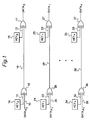
- FIG. 1 Shown in Figure 1 is a schematic diagram of the present invention wherein a digital data signal is input on line 10 as an input to XOR gate 16.
- the other input to XOR gate 16 is a key signal 14 which is input on line 12.
- the output at line 18 consists of the combination of data signal A0 and the key signal coming from key zero.
- the encrypted signal on signal line 18 is combined with the same key signal on line 13 through XOR gate 17.
- the receiver key zero, 15, is the same as the transmitter key zero, 14. If there are no faults, the output of XOR gate 17 should be the same as the original digital data signal input on line 10. In a similar fashion a second digital signal which under normal conditions will be identical to that on line 10, is input on line 20, and combined with a different key signal on line 22. The output of XOR gate 26 will therefore be different from that of XOR gate 16 when the data input signals are identical.
- the encrypted signal on line 28 is combined with the unique key signal on line 23 resulting in an output from XOR gate 27 which is identical to the original input data on line 20.
- XOR gate 27 which is identical to the original input data on line 20.
- the data outputs from the decryption XOR gates 17 and 27 are now identical, the intermediate, or encrypted, signals on lines 18 and 28 will be different as a result of the combination with the unique keys on lines 12 and 22.
- the output, or data signals from XOR gates 17, 27 and 37 should be identical with identical data inputs on lines 10, 20 and 30. Utilizing a comparison of the outputs of XOR gates 17, 27 and 37, various failures or faults can be detected. For example, if line 18 should short to line 28, the resultant identical signal will be input to gates 17 and 27. Since gates 17 and 27 are receiving different key inputs on lines 13 and 23, respectively, the outputs of gates 17 and 27 will be different and this difference will be detected by the comparison of the output data streams. The comparison may be made using any of numerous known apparatus or methods for comparison of digital signals.
- the encrypted signals on the signal lines will also be different.
- the dominant signal will appear on the affected lines.
- the signals are then decrypted by combining the encrypted signals with their corresponding key signals, any short or collision will cause a difference in output data that should be identical.
- a short of one of the encrypted lines to ground or an open will be detected through the comparison of the decrypted data with that of the other signal lines.
- An additional feature of the fault detection system is a shift in the frequency content of the encrypted data signal when certain particular keys are used.
- a data signal comprising first a high frequency content, then a low frequency content is mixed with, in the first example a key equal to a constant or continuous logical one and in a second example with a key equal to an alternating zero and one bit pattern.
- a resultant encrypted data signal in the case where the key is equal to a constant logical one is simply the inverse of the original data signal.
- the encrypted data signal becomes a steady low signal for an input data signal equal to alternating ones and zeros, and it becomes an alternating zero and one pattern where the input data stream is a steady logical zero. It can be seen from this example that by appropriate selection of the key signal, the frequency content of the encrypted signal may be shifted from a high frequency to a low frequency content or vise versa.
- the frequency of the encrypted data will tend to be the inverse of the unencrypted data.
- the resultant encrypted data has a low frequency, or in this case a steady state value.
- the encrypted data has a high frequency content.
- This frequency shift can be used to detect errors caused by frequency dependent faults such as those caused by reactances. For example, this will cause any DC component of NRZI encrypted signals to be different, thereby facilitating the detection of a level-shift induced bit error rate (BER).
- BER level-shift induced bit error rate
- the power usage for various data patterns may be made more nearly constant by changing the frequency spectrum and polarity of the encrypted signals. For example, if the unencrypted data consisted of primarily logical zeros there would be a significant power change between that data signal and a data signal which consisted primarily of logical ones. By encrypting the like data input signals with different keys the encrypted data produces an overall average data signal with a more or less constant power requirement.
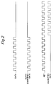
- Figure 3 illustrates a specific implementation utilizing four separate data signal lines and the specific corresponding key signals shown on lines 60, 70, 80 and 90.
- the input data are identical and comprise a series of alternating high and low digital data signals as shown on line 50.
- the key has been selected to be a constant logical zero.
- the resultant output from the XOR gate is simply a repeat of the encrypted input data, as shown by line 61 having the identical waveform of line 50.
- the key is selected, as shown on line 70, to be a series of alternating logical zeros and ones.
- Line 71 shows that the encrypted data signal now takes on a different waveform from that of line 61.
- the third key labeled as Key 2 in Figure 3, is selected to be a constant logical one.
- the output of the XOR gate will simply be an inversion of the original input signal. This can be seen by noting that waveform 81 is simply the inverse of the original data signal shown as waveform 50.
- the fourth key signal is selected to be a series of alternating ones and zeros, but of reverse polarity from that of Key 1 shown as waveform 70. It can be seen that this key input results in the fourth encrypted data signal waveform 91, having a similar shape, but inverted from that of waveform 71.
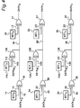
- the A data input signals on lines 10 , 20 and 30 may be transmitting at the same time as the B data signal lines on 110, 120 and 130.
- the data on signal lines 18, 28 and 38 would appear normal in that all of the signals would match.
- this collision fault can be detected.
- the signals appearing on 18, 28 and 38 will become the dominant value (either a 0 or a 1 depending on the signal means).
- Lines with different keys should have different values, but when simultaneous transmission causes a collision, the signals will be the same. This is detected at the receivers when the signals are recombined with the key signals.
- the encryption or decryption respectfully may be easily implemented by simply inverting the inputs to the parallel-to-serial converter, or the outputs from the serial-to-parallel converter, respectively. Where applicable, this method may be used to replace the key generators and XOR gates previously described.
- the decoding with a key repetition smaller than the number of stages in the serial-to-parallel converter may be accomplished without adding any additional hardware. The "decoding" is accomplished by simply utilizing the appropriate Q or Q not outputs of the converter stages.
- the output of an XOR gate having a data signal and a constant logical zero as inputs is the same as the original data signal.
- the XOR gate may simply be deleted.
- the output of an XOR gate having a data signal and a constant logical one as inputs is the original data signal inverted.
- the XOR gate may be replaced by an inverter.
- signal line may be any communication path, such as a wire, fiber optic conductor or RF channel, and the exclusive OR gate means may be substituted with any functional equivalent for combining a data signal with a key signal to obtain an encrypted or cyphered signal.
Landscapes
- Engineering & Computer Science (AREA)
- Theoretical Computer Science (AREA)
- Computer Security & Cryptography (AREA)
- Quality & Reliability (AREA)
- Physics & Mathematics (AREA)
- General Engineering & Computer Science (AREA)
- General Physics & Mathematics (AREA)
- Computer Networks & Wireless Communication (AREA)
- Signal Processing (AREA)
- Dc Digital Transmission (AREA)
- Detection And Prevention Of Errors In Transmission (AREA)
Claims (10)
- Dispositif de détection de défauts destiné à être utilisé pour l'émission d'un premier jeu de signaux de données numériques redondants multiples sur une pluralité de lignes de signaux (18, 28, 38) comprenant:une pluralité de moyens formant portes OU exclusif d'émission (16, 26, 36), chacun étant destiné à recevoir comme entrées un signal dudit premier jeu de signaux de données numériques redondants multiples (A0, A1, An) et un signal de clé de code unique (14, 24, 34) correspondant à l'une de ladite pluralité de lignes de signaux, la sortie de chacun d'entre eux étant couplée à l'une de ladite pluralité de lignes de signaux (18, 28, 38);une pluralité de moyens formant portes OU exclusif de réception (17, 27, 37), chacun d'entre eux étant couplé à l'une de ladite pluralité de lignes de signaux (18, 28, 38) et est destiné à recevoir comme entrées le signal sur ladite ligne de ladite pluralité de lignes de signaux et ledit signal de clé de code unique (15, 25, 35) correspondant à ladite ligne desdites lignes de signaux; etun moyen de comparaison destiné à comparer les sorties desdits moyens formant portes OU exclusif de réception.
- Dispositif selon la revendication 1 pour quatre lignes de signaux, caractérisé en ce que lesdits signaux de clé de code uniques comprennent un premier signal de clé de code (60) qui correspond à un niveau logique zéro continu, un deuxième de signal de clé de code (70) qui correspond à un profil binaire alternant entre zéro et un à fréquence constante, un troisième signal de clé de code (80) qui correspond à un niveau logique un continu, et un quatrième signal de clé de code (90) qui correspond au signal inverse dudit deuxième signal de clé de code.
- Dispositif selon la revendication 1, caractérisé en ce que lesdits signaux de clé de code (60, 70, 80, 90) sont sélectionnés pour produire des signaux de données sur lesdites lignes de signaux qui présentent un niveau de puissance en courant continu sensiblement constant.
- Dispositif selon la revendication 1, caractérisé en ce que lesdits signaux de clé de code sont sélectionnés pour produire des signaux de données sur lesdites lignes de signaux qui présentent un niveau de puissance en courant alternatif sensiblement constant.
- Dispositif selon la revendication 1, destiné à émettre en plus un second jeu de signaux numériques redondants multiples sur ladite pluralité de lignes de signaux (18, 28, 38) comprenant en outre:
une pluralité supplémentaire de moyens formant portes OU exclusif d'émission (116, 126, 136), chacun étant destiné à recevoir comme entrées un signal dudit second jeux de signaux de données numériques redondants multiples (B0, B1, Bn) et un signal de clé de code unique (114, 124, 134) correspondant à l'une de ladite pluralité de lignes de signaux, la sortie de chacun d'entre eux étant couplée à ladite ligne de ladite pluralité de lignes de signaux. - Dispositif de détection de défauts destiné à émettre des premier, deuxième, troisième et quatrième signaux de données numériques identiques sur des première, deuxième, troisième et quatrième lignes de signaux respectives comprenant:un premier moyen formant porte OU exclusif d'émission (16) afin de recevoir ledit premier signal de données numériques (A0) et un premier signal de clé de code (14), la sortie de celui-ci étant couplée à ladite première ligne de signal (18);un premier moyen formant porte OU exclusif de réception (17) couplé à ladite première ligne de signal (18), afin de recevoir comme entrées le signal sur ladite première ligne de signal et ledit premier signal de clé de code;un deuxième moyen formant porte OU exclusif d'émission (26) afin de recevoir ledit deuxième signal de données numériques (A1) et un deuxième signal de clé de code (24), la sortie de celui-ci étant couplée à ladite deuxième ligne de signal (28);un deuxième moyen formant porte OU exclusif de réception (27) couplé à ladite deuxième ligne de signal (28), afin de recevoir comme entrées le signal sur ladite deuxième ligne de signal et ledit deuxième signal de clé de code;un troisième moyen formant porte OU exclusif d'émission (36), afin de recevoir ledit troisième signal de données numériques (An) et un troisième signal de clé de code (34), la sortie de celui-ci étant couplée à ladite troisième ligne de signal (38);un troisième moyen formant porte OU exclusif de réception (37) couplé à ladite troisième ligne de signal (38), afin de recevoir comme entrées le signal sur ladite troisième ligne de signal et ledit troisième signal de clé de code;un quatrième moyen formant porte OU exclusif d'émission, afin de recevoir ledit quatrième signal de données numériques et un quatrième signal de clé de code, la sortie de celui-ci étant couplée à ladite quatrième ligne de signal;un quatrième moyen formant porte OU exclusif de réception, couplé à ladite quatrième ligne de signal, afin de recevoir comme entrées le signal sur ladite quatrième ligne de signal et ledit quatrième signal de clé de code; etun moyen de comparaison couplé aux sorties desdits premier, deuxième, troisième et quatrième moyens formant porte OU exclusif de réception, afin de comparer les sorties desdits premier, deuxième, troisième et quatrième moyens formant portes OU exclusif de réception.
- Procédé de détection de défauts, dans un système destiné à émettre une pluralité de signaux de données numériques redondants identiques sur une pluralité de lignes de signaux, comprenant les étapes de:combinaison de chacun desdits signaux numériques redondants identiques avec un signal de clé de code unique dans un moyen de combinaison afin de former un signal de données numériques crypté;émission de chacun desdits signaux de données numériques cryptés sur l'une de ladite pluralité de lignes de signaux,recombinaison de chacun desdits signaux de données numériques cryptés avec son signal de clé de code unique correspondant dans un moyen de recombinaison afin de produire un signal de données numériques décrypté; etcomparaison desdits signaux de données numériques décryptés afin de détecter des défauts, dans lequel, en l'absence de défaut, l'ensemble desdits signaux numériques décryptés sont identiques.
- Procédé selon la revendication 7, caractérisé en ce que ledit moyen de combinaison et ledit moyen de recombinaison sont constitués par des moyens formant portes OU exclusif.
- Procédé selon la revendication 8, caractérisé en ce que lesdits signaux de clé de code sont sélectionnés de manière à obtenir un niveau de puissance en courant continu sensiblement constant pour la moyenne desdits signaux numériques cryptés.
- Procédé selon la revendication 8, caractérisé en ce que lesdits signaux de clé de code sont sélectionnés pour obtenir un niveau de puissance en courant alternatif sensiblement constant pour la moyenne desdits signaux numériques cryptés.
Applications Claiming Priority (3)
| Application Number | Priority Date | Filing Date | Title |
|---|---|---|---|
| US07/995,107 US5307409A (en) | 1992-12-22 | 1992-12-22 | Apparatus and method for fault detection on redundant signal lines via encryption |
| PCT/US1993/012204 WO1994015420A1 (fr) | 1992-12-22 | 1993-12-14 | Appareil et procede de detection de defaillance par chiffrement sur des lignes de signaux redondants |
| US995107 | 1997-12-19 |
Publications (2)
| Publication Number | Publication Date |
|---|---|
| EP0676108A1 EP0676108A1 (fr) | 1995-10-11 |
| EP0676108B1 true EP0676108B1 (fr) | 1996-11-13 |
Family
ID=25541399
Family Applications (1)
| Application Number | Title | Priority Date | Filing Date |
|---|---|---|---|
| EP94905395A Expired - Lifetime EP0676108B1 (fr) | 1992-12-22 | 1993-12-14 | Appareil et procede de detection de defaillance par chiffrement sur des lignes de signaux redondants |
Country Status (6)
| Country | Link |
|---|---|
| US (1) | US5307409A (fr) |
| EP (1) | EP0676108B1 (fr) |
| JP (1) | JPH08505021A (fr) |
| CA (1) | CA2134559A1 (fr) |
| DE (1) | DE69305998T2 (fr) |
| WO (1) | WO1994015420A1 (fr) |
Cited By (1)
| Publication number | Priority date | Publication date | Assignee | Title |
|---|---|---|---|---|
| CN103997381A (zh) * | 2014-05-30 | 2014-08-20 | 成都佳发安泰科技股份有限公司 | 考场作弊信号智能识别与取证还原方法 |
Families Citing this family (40)
| Publication number | Priority date | Publication date | Assignee | Title |
|---|---|---|---|---|
| US5394471A (en) * | 1993-09-17 | 1995-02-28 | Bell Atlantic Network Services, Inc. | Method and system for proactive password validation |
| US5850448A (en) * | 1994-10-25 | 1998-12-15 | Bell Atlantic Network Services, Inc. | Programmed computer for generating pronounceable security passwords |
| US5606616A (en) * | 1995-07-03 | 1997-02-25 | General Instrument Corporation Of Delaware | Cryptographic apparatus with double feedforward hash function |
| US6363330B1 (en) | 1998-04-10 | 2002-03-26 | Satnam Singh Sampuran Alag | Thermocouple failure detection in power generation turbines |
| US6275503B1 (en) | 1998-07-24 | 2001-08-14 | Honeywell International Inc. | Method for transmitting large information packets over networks |
| US6804354B1 (en) | 1999-12-02 | 2004-10-12 | Honeywell International Inc. | Cryptographic isolator using multiplication |
| US6763363B1 (en) | 1999-12-02 | 2004-07-13 | Honeywell International Inc. | Computer efficient linear feedback shift register |
| US6760440B1 (en) | 1999-12-11 | 2004-07-06 | Honeywell International Inc. | One's complement cryptographic combiner |
| US6523139B1 (en) | 1999-12-17 | 2003-02-18 | Honeywell International Inc. | System and method for fail safe process execution monitoring and output control for critical systems |
| DE10037737B4 (de) * | 2000-08-02 | 2007-03-22 | Siemens Ag | Verfahren und Vorrichtung zur sicheren einkanaligen Auswertung von Sensorsignalen |
| US7277543B1 (en) | 2000-11-14 | 2007-10-02 | Honeywell International Inc. | Cryptographic combiner using two sequential non-associative operations |
| GB2404314B (en) * | 2002-01-25 | 2005-07-13 | Actix Ltd | Data transmission systems |
| US20050120208A1 (en) * | 2002-01-25 | 2005-06-02 | Albert Dobson Robert W. | Data transmission systems |
| EP1394559A1 (fr) * | 2002-08-27 | 2004-03-03 | Siemens Aktiengesellschaft | Procédé et dispositif pour détecter et corriger des erreurs de lignes défectueuses |
| US6813527B2 (en) | 2002-11-20 | 2004-11-02 | Honeywell International Inc. | High integrity control system architecture using digital computing platforms with rapid recovery |
| DE10320522A1 (de) * | 2003-05-02 | 2004-11-25 | Pilz Gmbh & Co. | Verfahren und Vorrichtug zum Steuern eines sicherheitskritischen Prozesses |
| JP2007517427A (ja) * | 2003-11-19 | 2007-06-28 | ハネウェル・インターナショナル・インコーポレーテッド | メービウス時間トリガ型通信 |
| US7649835B2 (en) * | 2003-11-19 | 2010-01-19 | Honeywell International Inc. | Unsynchronous mode brother's keeper bus guardian for a ring networks |
| US7372859B2 (en) * | 2003-11-19 | 2008-05-13 | Honeywell International Inc. | Self-checking pair on a braided ring network |
| US7515715B2 (en) * | 2004-07-08 | 2009-04-07 | Honeywell International Inc. | Information security for aeronautical surveillance systems |
| DE102005001953A1 (de) * | 2005-01-14 | 2006-07-27 | Infineon Technologies Ag | Verfahren und Schaltungsanordnung zur Überprüfung eines Datensatzes mit mehreren Datenworten |
| DE102005012632A1 (de) * | 2005-03-18 | 2006-09-21 | Infineon Technologies Ag | Verfahren und Schaltungsanordnung zur geschützten Übertragung von Datenworten |
| KR100699836B1 (ko) * | 2005-03-19 | 2007-03-27 | 삼성전자주식회사 | 스칼라 곱에서 dfa 대책을 위한 장치 및 방법 |
| US7386743B2 (en) * | 2005-06-09 | 2008-06-10 | International Business Machines Corporation | Power-managed server and method for managing power consumption |
| US7664968B2 (en) * | 2005-06-09 | 2010-02-16 | International Business Machines Corporation | System and method for managing power usage of a data processing system subsystem |
| US7421599B2 (en) * | 2005-06-09 | 2008-09-02 | International Business Machines Corporation | Power management server and method for managing power consumption |
| US7509506B2 (en) * | 2005-06-09 | 2009-03-24 | International Business Machines Corporation | Hierarchical system and method for managing power usage among server data processing systems |
| US7467311B2 (en) * | 2005-06-09 | 2008-12-16 | International Business Machines Corporation | Distributed system and method for managing power usage among server data processing systems |
| KR20080013130A (ko) * | 2006-08-07 | 2008-02-13 | 삼성전자주식회사 | 표시 장치의 구동 장치 및 구동 방법 |
| US7668084B2 (en) * | 2006-09-29 | 2010-02-23 | Honeywell International Inc. | Systems and methods for fault-tolerant high integrity data propagation using a half-duplex braided ring network |
| US20080098234A1 (en) * | 2006-10-20 | 2008-04-24 | Honeywell International Inc. | Fault-containment and/or failure detection using encryption |
| US7889683B2 (en) * | 2006-11-03 | 2011-02-15 | Honeywell International Inc. | Non-destructive media access resolution for asynchronous traffic in a half-duplex braided-ring |
| US7912094B2 (en) * | 2006-12-13 | 2011-03-22 | Honeywell International Inc. | Self-checking pair-based master/follower clock synchronization |
| US7656881B2 (en) * | 2006-12-13 | 2010-02-02 | Honeywell International Inc. | Methods for expedited start-up and clique aggregation using self-checking node pairs on a ring network |
| DE102007008168A1 (de) * | 2007-02-19 | 2008-08-28 | Siemens Ag | Schaltungsvorrichtung und entsprechendes Verfahren zum Ansteuern einer Last |
| US7778159B2 (en) * | 2007-09-27 | 2010-08-17 | Honeywell International Inc. | High-integrity self-test in a network having a braided-ring topology |
| DE102007048579B4 (de) * | 2007-10-10 | 2016-05-19 | Airbus Operations Gmbh | Mehrzweck-Flugbegleiterpanel |
| US8817597B2 (en) * | 2007-11-05 | 2014-08-26 | Honeywell International Inc. | Efficient triple modular redundancy on a braided ring |
| US8805590B2 (en) * | 2009-12-24 | 2014-08-12 | International Business Machines Corporation | Fan speed control of rack devices where sum of device airflows is greater than maximum airflow of rack |
| US8533557B2 (en) | 2011-01-28 | 2013-09-10 | Infineon Technologies Ag | Device and method for error correction and protection against data corruption |
Family Cites Families (6)
| Publication number | Priority date | Publication date | Assignee | Title |
|---|---|---|---|---|
| DE2706421C2 (de) * | 1977-02-16 | 1979-03-15 | Licentia Patent-Verwaltungs-Gmbh, 6000 Frankfurt | Verfahren zum Einstellen von Schlüsseltextgeneratoren in Chiffriergeräten |
| FR2422582A1 (fr) * | 1978-04-12 | 1979-11-09 | Coignet Sa | Detecteur de composition de moufflage d'un enfin de levage |
| DE3512126C1 (de) * | 1985-04-03 | 1986-08-14 | ANT Nachrichtentechnik GmbH, 7150 Backnang | Wortweise arbeitender,multiplikativer Verwuerfler und Entwuerfler |
| US4819225A (en) * | 1987-03-09 | 1989-04-04 | Hochstein Peter A | Redundant and fault tolerant communication link |
| DE3713825A1 (de) * | 1987-04-24 | 1988-11-10 | Siemens Ag | Hochverfuegbares serielles bussystem |
| US5161186A (en) * | 1991-09-06 | 1992-11-03 | International Business Machines Corporation | System for secure and private communication in a triple-connected network |
-
1992
- 1992-12-22 US US07/995,107 patent/US5307409A/en not_active Expired - Lifetime
-
1993
- 1993-12-14 JP JP6515276A patent/JPH08505021A/ja active Pending
- 1993-12-14 EP EP94905395A patent/EP0676108B1/fr not_active Expired - Lifetime
- 1993-12-14 WO PCT/US1993/012204 patent/WO1994015420A1/fr not_active Ceased
- 1993-12-14 CA CA002134559A patent/CA2134559A1/fr not_active Abandoned
- 1993-12-14 DE DE69305998T patent/DE69305998T2/de not_active Expired - Fee Related
Cited By (2)
| Publication number | Priority date | Publication date | Assignee | Title |
|---|---|---|---|---|
| CN103997381A (zh) * | 2014-05-30 | 2014-08-20 | 成都佳发安泰科技股份有限公司 | 考场作弊信号智能识别与取证还原方法 |
| CN103997381B (zh) * | 2014-05-30 | 2016-01-20 | 成都佳发安泰科技股份有限公司 | 考场作弊信号智能识别与取证还原方法 |
Also Published As
| Publication number | Publication date |
|---|---|
| DE69305998D1 (de) | 1996-12-19 |
| DE69305998T2 (de) | 1997-05-28 |
| JPH08505021A (ja) | 1996-05-28 |
| WO1994015420A1 (fr) | 1994-07-07 |
| US5307409A (en) | 1994-04-26 |
| CA2134559A1 (fr) | 1994-07-07 |
| EP0676108A1 (fr) | 1995-10-11 |
Similar Documents
| Publication | Publication Date | Title |
|---|---|---|
| US5307409A (en) | Apparatus and method for fault detection on redundant signal lines via encryption | |
| US6430230B1 (en) | Methods of encoding payload bits for transmission | |
| US3775746A (en) | Method and apparatus for detecting odd numbers of errors and burst errors of less than a predetermined length in scrambled digital sequences | |
| US4425666A (en) | Data encoding and decoding communication system for three frequency FSK modulation and method therefor | |
| EP0731586B1 (fr) | Code ternaire équilibré | |
| JP3419520B2 (ja) | データ通信方法および装置 | |
| US6912284B1 (en) | Self-Authenticating cryptographic apparatus | |
| US7760881B2 (en) | Data processing apparatus and data reception processing apparatus | |
| US3962647A (en) | Biphase waveform generator using shift registers | |
| EP0243938B1 (fr) | Système de surveillance d'un canal de remplacement utilisant un signal de vérification comportant deux configurations de code à n bits différentes assemblées séquentiellement et aléatoirement | |
| US6192093B1 (en) | Enhanced CIMT coding system and method with automatic word alignment for simplex operation | |
| US5655078A (en) | Apparatus and method for encoding data in a fiber data distributed interface (FDDI) | |
| JPH0681166B2 (ja) | デイジタル伝送装置 | |
| CA2113392C (fr) | Eliminateur d'erreur de phase utilisant des detecteurs de mot unique pour signaux mdpq | |
| US4864617A (en) | System and method for reducing deadlock conditions caused by repeated transmission of data sequences equivalent to those used for inter-device signalling | |
| US3190958A (en) | Frequency-shift-keyed signal generator with phase mismatch prevention means | |
| JPS5936454A (ja) | 擬似ランダムシ−クエンス発生器を使用する一体化されたスクランブラ−エンコ−ダ | |
| US3990009A (en) | Method and apparatus for uniquely encoding channels in a digital transmission system | |
| AU611562B2 (en) | Enciphering and deciphering device for high bit-rate transmission systems | |
| JPH0746135A (ja) | 3値符号送受信回路 | |
| JPH07245630A (ja) | 高速データ伝送方式 | |
| JPH0744473A (ja) | 信号授受回路 | |
| JPS60199258A (ja) | デイジタル通信方式 | |
| KR19980063013A (ko) | 동기식 스트림 암호의 동기방법 및 그 장치 | |
| JPS6096049A (ja) | 障害探索方式 |
Legal Events
| Date | Code | Title | Description |
|---|---|---|---|
| PUAI | Public reference made under article 153(3) epc to a published international application that has entered the european phase |
Free format text: ORIGINAL CODE: 0009012 |
|
| 17P | Request for examination filed |
Effective date: 19950609 |
|
| AK | Designated contracting states |
Kind code of ref document: A1 Designated state(s): DE FR GB IT |
|
| GRAG | Despatch of communication of intention to grant |
Free format text: ORIGINAL CODE: EPIDOS AGRA |
|
| GRAH | Despatch of communication of intention to grant a patent |
Free format text: ORIGINAL CODE: EPIDOS IGRA |
|
| GRAH | Despatch of communication of intention to grant a patent |
Free format text: ORIGINAL CODE: EPIDOS IGRA |
|
| 17Q | First examination report despatched |
Effective date: 19960502 |
|
| GRAA | (expected) grant |
Free format text: ORIGINAL CODE: 0009210 |
|
| AK | Designated contracting states |
Kind code of ref document: B1 Designated state(s): DE FR GB IT |
|
| REF | Corresponds to: |
Ref document number: 69305998 Country of ref document: DE Date of ref document: 19961219 |
|
| ET | Fr: translation filed | ||
| ITF | It: translation for a ep patent filed | ||
| PLBE | No opposition filed within time limit |
Free format text: ORIGINAL CODE: 0009261 |
|
| STAA | Information on the status of an ep patent application or granted ep patent |
Free format text: STATUS: NO OPPOSITION FILED WITHIN TIME LIMIT |
|
| 26N | No opposition filed | ||
| REG | Reference to a national code |
Ref country code: GB Ref legal event code: IF02 |
|
| PGFP | Annual fee paid to national office [announced via postgrant information from national office to epo] |
Ref country code: GB Payment date: 20031105 Year of fee payment: 11 |
|
| PGFP | Annual fee paid to national office [announced via postgrant information from national office to epo] |
Ref country code: FR Payment date: 20031201 Year of fee payment: 11 |
|
| PG25 | Lapsed in a contracting state [announced via postgrant information from national office to epo] |
Ref country code: GB Free format text: LAPSE BECAUSE OF NON-PAYMENT OF DUE FEES Effective date: 20041214 |
|
| PGFP | Annual fee paid to national office [announced via postgrant information from national office to epo] |
Ref country code: DE Payment date: 20041230 Year of fee payment: 12 |
|
| GBPC | Gb: european patent ceased through non-payment of renewal fee |
Effective date: 20041214 |
|
| PG25 | Lapsed in a contracting state [announced via postgrant information from national office to epo] |
Ref country code: FR Free format text: LAPSE BECAUSE OF NON-PAYMENT OF DUE FEES Effective date: 20050831 |
|
| REG | Reference to a national code |
Ref country code: FR Ref legal event code: ST |
|
| PG25 | Lapsed in a contracting state [announced via postgrant information from national office to epo] |
Ref country code: IT Free format text: LAPSE BECAUSE OF NON-PAYMENT OF DUE FEES Effective date: 20051214 |
|
| PG25 | Lapsed in a contracting state [announced via postgrant information from national office to epo] |
Ref country code: DE Free format text: LAPSE BECAUSE OF NON-PAYMENT OF DUE FEES Effective date: 20060701 |
|
| P01 | Opt-out of the competence of the unified patent court (upc) registered |
Effective date: 20230525 |