EP0676247B1 - Auftragskopf zur dosierten Abgabe von strömenden Medien - Google Patents
Auftragskopf zur dosierten Abgabe von strömenden Medien Download PDFInfo
- Publication number
- EP0676247B1 EP0676247B1 EP95104269A EP95104269A EP0676247B1 EP 0676247 B1 EP0676247 B1 EP 0676247B1 EP 95104269 A EP95104269 A EP 95104269A EP 95104269 A EP95104269 A EP 95104269A EP 0676247 B1 EP0676247 B1 EP 0676247B1
- Authority
- EP
- European Patent Office
- Prior art keywords
- rocker
- valve
- applicator head
- head according
- piezoelectric
- Prior art date
- Legal status (The legal status is an assumption and is not a legal conclusion. Google has not performed a legal analysis and makes no representation as to the accuracy of the status listed.)
- Expired - Lifetime
Links
- 239000012530 fluid Substances 0.000 title abstract 2
- 239000011248 coating agent Substances 0.000 title 1
- 238000000576 coating method Methods 0.000 title 1
- 239000004831 Hot glue Substances 0.000 claims description 18
- 239000000463 material Substances 0.000 claims description 5
- 238000005265 energy consumption Methods 0.000 claims description 4
- 239000003990 capacitor Substances 0.000 claims description 3
- 239000000314 lubricant Substances 0.000 claims description 2
- 239000003973 paint Substances 0.000 claims description 2
- 238000004519 manufacturing process Methods 0.000 abstract description 5
- 238000000034 method Methods 0.000 description 9
- 238000010276 construction Methods 0.000 description 6
- 238000010438 heat treatment Methods 0.000 description 6
- 238000000926 separation method Methods 0.000 description 6
- 239000000758 substrate Substances 0.000 description 5
- 229910001369 Brass Inorganic materials 0.000 description 4
- 239000010951 brass Substances 0.000 description 4
- 230000005669 field effect Effects 0.000 description 4
- 238000005452 bending Methods 0.000 description 3
- 238000009760 electrical discharge machining Methods 0.000 description 3
- 238000007789 sealing Methods 0.000 description 3
- 239000000853 adhesive Substances 0.000 description 2
- 230000001070 adhesive effect Effects 0.000 description 2
- 238000010586 diagram Methods 0.000 description 2
- 238000006073 displacement reaction Methods 0.000 description 2
- 238000005516 engineering process Methods 0.000 description 2
- 238000010792 warming Methods 0.000 description 2
- 229910000760 Hardened steel Inorganic materials 0.000 description 1
- 239000004809 Teflon Substances 0.000 description 1
- 229920006362 Teflon® Polymers 0.000 description 1
- 230000037007 arousal Effects 0.000 description 1
- 239000000919 ceramic Substances 0.000 description 1
- 238000006243 chemical reaction Methods 0.000 description 1
- 230000006735 deficit Effects 0.000 description 1
- 230000005284 excitation Effects 0.000 description 1
- 239000003292 glue Substances 0.000 description 1
- 230000003287 optical effect Effects 0.000 description 1
- 230000004043 responsiveness Effects 0.000 description 1
- 239000011435 rock Substances 0.000 description 1
- 239000004753 textile Substances 0.000 description 1
Images

Classifications
-
- F—MECHANICAL ENGINEERING; LIGHTING; HEATING; WEAPONS; BLASTING
- F16—ENGINEERING ELEMENTS AND UNITS; GENERAL MEASURES FOR PRODUCING AND MAINTAINING EFFECTIVE FUNCTIONING OF MACHINES OR INSTALLATIONS; THERMAL INSULATION IN GENERAL
- F16K—VALVES; TAPS; COCKS; ACTUATING-FLOATS; DEVICES FOR VENTING OR AERATING
- F16K31/00—Actuating devices; Operating means; Releasing devices
- F16K31/004—Actuating devices; Operating means; Releasing devices actuated by piezoelectric means
- F16K31/007—Piezoelectric stacks
-
- B—PERFORMING OPERATIONS; TRANSPORTING
- B05—SPRAYING OR ATOMISING IN GENERAL; APPLYING FLUENT MATERIALS TO SURFACES, IN GENERAL
- B05C—APPARATUS FOR APPLYING FLUENT MATERIALS TO SURFACES, IN GENERAL
- B05C5/00—Apparatus in which liquid or other fluent material is projected, poured or allowed to flow on to the surface of the work
- B05C5/001—Apparatus in which liquid or other fluent material is projected, poured or allowed to flow on to the surface of the work incorporating means for heating or cooling the liquid or other fluent material
-
- B—PERFORMING OPERATIONS; TRANSPORTING
- B05—SPRAYING OR ATOMISING IN GENERAL; APPLYING FLUENT MATERIALS TO SURFACES, IN GENERAL
- B05C—APPARATUS FOR APPLYING FLUENT MATERIALS TO SURFACES, IN GENERAL
- B05C5/00—Apparatus in which liquid or other fluent material is projected, poured or allowed to flow on to the surface of the work
- B05C5/02—Apparatus in which liquid or other fluent material is projected, poured or allowed to flow on to the surface of the work the liquid or other fluent material being discharged through an outlet orifice by pressure, e.g. from an outlet device in contact or almost in contact, with the work
- B05C5/0225—Apparatus in which liquid or other fluent material is projected, poured or allowed to flow on to the surface of the work the liquid or other fluent material being discharged through an outlet orifice by pressure, e.g. from an outlet device in contact or almost in contact, with the work characterised by flow controlling means, e.g. valves, located proximate the outlet
Definitions
- the invention relates to an application head for metered Delivery of flowing media, in particular Hot melt adhesive, lubricants, paints or the like, with a housing in which a valve drive and at least a valve nozzle is arranged with at least two connected to a voltage source, from side by side arranged piezo stacks existing piezoelectric Element, with the piezo stack alternately on act on a rocker on which a valve member is arranged is and that at the hinge end portion of the rocker Piezo stacking at the same distance on both sides an axis running perpendicularly through the joint are arranged and alternately on the seesaw act.
- Such prior art is for example from SU-A-928089 and JP-A-3 234 981.
- two act in each case Piezo stacks arranged on both sides of a rocker axis alternately on the rocker so that the valve member or the rocker arm, especially at its free end area, one that runs perpendicular to the movement of the piezo stack Swiveling movement takes place.
- a valve nozzle is arranged on both sides.
- a non-printable, obviously previously used order header known, for applying hot glue for example on one made of cardboard, paper, textile fleece and the like existing substrate is used.
- the application head has a valve drive which consists of a piezoelectric element, the piezoelectric element directly on the valve member acts.
- the piezoelectrically driven one Order head has the advantage that its maximum Frequency is significantly higher than that of electro-magnetic or pneumatically operated application heads.
- a piezoelectrically driven one Application head much smaller than electrical or pneumatically driven application heads.
- piezoelectric elements are fundamentally when heating up significantly, there is piezoelectric Element for temperature compensation reasons of three arranged side by side in parallel Piezo stacks, which are spring-loaded in a complex manner are, with only the middle piezo stack serves to actuate the valve. This type of temperature compensation makes the production of the known more expensive Application head considerably.
- the temperatures are between 150 and 200 ° Celsius, the risk that the piezoelectric element over its temperature limit of 100 to 130 ° Celsius warmed and destroyed.
- the object of the invention is a for the application of hot glues in particular on a passed substrate to suitable applicator create the easy and inexpensive to manufacture and not just in the low temperature range, but can also be used in the high temperature range.
- the application head according to the invention basically has the advantage that the piezoelectric valve drive with automatic temperature compensation is now suitable to have a single valve nozzle inside a short opening and closing cycle of only 0.8 to 0.25 ms to actuate.
- the Valve drive according to the invention very simply from a few Parts built, making it inexpensive on the one hand is to be produced and, on the other hand, a low overall Has size, which makes the string from numerous application heads side by side confined space becomes possible.
- This structure of the valve drive according to the invention has the advantage that the rocker, as well as the base part from a workpiece using the known spark erosion process can be produced. This will created a very small, compact drive component. The width of the gap between the rocker and the base part only so large that the seesaw during operation of the application head is freely movable.
- a further embodiment of the Invention is characterized in that each piezo stack is glued to a connecting part, which using a flexible, narrow material bridge with the rocker is connected.
- the housing is composed of two housing parts, between which a thermal separation layer is arranged which is only from the rod-shaped valve member is broken.
- the first housing part includes that of the piezoelectric element and the Rocker existing valve drive and the second housing part has a tempered channel for the medium as well the valve opening to be closed by a valve body on.
- This embodiment of an application head according to the invention can advantageously also for metered Delivery of hot media, especially hot glue used become. Due to the two-part construction of the housing and the intermediate thermal interface is already a very significant thermal Decoupling of the two parts achieved. Furthermore enables the construction of the valve drive according to the invention also the spatial separation of the for Passage of the valve member necessary opening and Drive consisting of piezo stacks. This will make the necessarily existing weak zone with respect to the thermal separation of the two housing parts significantly spaced from the piezo stacks. That is, the heat loss in the area cannot be completely prevented of the valve member connecting the two housing parts leads to local warming, but it does is not so great as to endanger the piezo stack consists.
- valve member a transverse to the longitudinal extension of the Rock the running cardan. This in the area of the first housing part arranged in the valve member Bending cardan initially has the function that compensate for circular swiveling movement of the rocker.
- the flexible cardan also has the significant advantage that he has a high thermal resistance owns and thus only in the valve stem small amount of heat can be transferred.
- the invention is between the voltage source and the piezoelectric elements an energy consumption reducing charge pump arrangement available, which essentially a full charge exchange enables.
- the reduced energy consumption of the piezoelectric Elements performs in a particularly advantageous manner also to lower heat losses in the electronics, which heats the piezo stack to a lesser extent become.
- the operation of the application head overall cheaper.
- the charge pump arrangement can advantageously one consisting of a coil and a capacitor Cache, a variety of on the Buffer and the piezo stack acting Transistors and one that determines the recharging processes Have programmable controls. Through this electronic It is possible to arrange the electrical charge essentially entirely from a piezo stack to transform to the other piezo stack so that only so much energy during the operation of the application head must be supplied that the heat losses and which due to the conversion of electrical energy into mechanical energy losses are covered.
- a particularly preferred embodiment has a valve drive with a displacement measuring device on which consists of a stationary printed circuit board and two attached spaced apart current-carrying coils exists between the one tongue-like extension of the seesaw protrudes.
- the application head is metered Total delivery of hot glue with the reference number Designated 10.
- the application head has a housing 11 which is divided into housing parts 12 and 13. Between screw-connected housing parts 12 and 13 is one thermal separation layer 14 arranged.
- valve drive in the housing part 12 15, a chamber 16 for electronic, not shown Components and an electrical supply and Control line 18 available.
- the housing part 13 includes a rod-shaped valve member 19, which in protrudes a valve head 20, a heating device 21 and a hot glue channel 22.
- the valve drive 15 takes place via one of two Piezo stacking 23 existing piezoelectric element 24, which on one side on a resilient, with Screws S attached cover plate 17 abuts.
- the Piezo stacks 23 are each made of approximately 200 0.1 mm thick ceramic panes that are glued together become.
- valve drive 15 has a rocker 25, which via a joint 26 with a base part 27 is connected. While the valve member 19 by means of a screw connection 29 at a free end area 28 of the rocker 25 is attached are on the joint side End region 30 of rocker 25, the two piezo stacks 23 articulated in the manner described below.
- Connecting parts 31 are integral with one another connected. They are made up of one Component by using the EDM process been made. So there is the seesaw 25 with the Base part 27 connecting joint 26 made of a flexible, narrow material bridge, which on both sides by a the relative movement of the rocker 25 relative to the base part 27 serving gap 32 is limited. The same Ways are also the connecting parts 31, which with the piezo stacks 23 are glued, each via a Joint 33 integrally connected to the rocker 25.
- the piezo stacks 23a and 23b are one on both sides vertical axis G running through the joint in each case at a distance d indirectly via the joint 33 connected to the rocker 25. This results in connection with the flexible storage of the piezo stack 23a and 23b through the cover plate 17 an automatic Temperature compensation.
- rod-shaped valve member 19 extends through Area of an opening 34, the thermal separating layer 14 between the housing parts 12 and 13.
- a brass sleeve 35 which is the Includes a sealing system.
- the brass sleeve 35 has a leak hole 36 which is transverse to the longitudinal axis of the valve member 19 extends. If one in the lower area the brass sleeve 35 arranged teflon-filled Ring seal 37 should leak, emerges from the Leak hole 36 recognizable from hot glue.
- the leak hole 36 is also a mounting hole for that in the housing part 13, adjacent to the brass sleeve 35 arranged heating cartridge 21 is provided.
- heating cartridge 21 Above the heating cartridge 21 is dashed in 1 shows a temperature sensor 38. Below the heating cartridge 21 is in the hot glue channel 22 under high pressure of the hot glue from a not shown Melter and a heated Hose line transported to the valve head 20.
- the hot glue channel 22 opens into the valve member 19 surrounding annular space 41.
- a valve body 42 At the free end, the Valve member 19 a valve body 42 which with one of the Rotation adjustment of the valve member serving actuation groove N is provided. By means of the valve body 42 an existing valve opening in the valve head 20 can be closed.
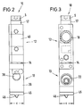
- FIG. 2 and 3 are side views of the application head 10 shown.
- Fig. 2 shows the side view according to a view arrow labeled II in FIG. 1.
- the order head 10 has only a small width c, which at Embodiment is only 12 mm. It will possible a large number of application heads 10 side by side in an adhesive application machine using the fastening device 40 to arrange.
- the thermal Interface 14 Between the housing parts 12 and 13 is the thermal Interface 14 to recognize. While above of the housing part 12 which is fastened by means of screws S. Cover plate 17 is shown, shows the side view of the housing part 13 on the one hand, the leak hole 36 and the nozzle plate serving to fasten the nozzle component 46 45, which in turn by means of not shown Screws is connected to the valve head 20.
- Fig. 3 is also the side view according to a view arrow labeled III in FIG. 1 to see. In this side view are additional nor the control and supply line 18 and the Hot glue channel 22 to recognize.
- a movement of the at rest on the sealing surfaces 43 circumferential valve body 42 is from the piezo stacks 23a and 23b causes that the latter alternately from an electrical potential be acted upon and expand.
- valve rod 29 transverse to the longitudinal extension of the rocker 25 arranged bending cardan 39, which is only a thickness b from 0.1 to 0.4 mm.
- bending cardan 39 which is only a thickness b from 0.1 to 0.4 mm.
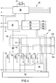
- valve electronics 48 The control and regulation of the two piezo stacks 23a and 23b existing piezoelectric element 24 is carried out by special valve electronics 48, the essentially in the chamber shown in Fig. 1 16 is arranged.
- the in a block diagram in The valve electronics 48 shown in FIG. 4 enables on the one hand the alternating voltage application of the two piezo stacks 23a and 23b and on the other hand one particularly energy-saving and therefore also with low Operation of the application head subject to heat loss 10th
- valve electronics 48 has a so-called Charge pump assembly 49, which basically is shown in Fig. 4.
- the charge pump arrangement 49 essentially has a buffer 50 and several power field effect transistors 51 on, with the latch 50 as well as the power field effect transistors 51 with both Piezo stacks 23a and 23b are connected.
- the cache 50 includes a coil 52 and a capacitor 53.
- the energy saving is achieved in the operation of the piezoelectric element 24 by the so-called Push-pull arrangement of the piezo stacks 23a and 23b usable transfer principle achieved.
- this reloading principle means that each stored in a piezo stack 23a or 23b Energy (charge) "in portions" in each another piezo stack 23a or 23b is transformed. Basically, this takes place within the charge pump arrangement 49 in that on the one hand the charge of a Piezo stack 23a or 23b temporarily in the buffer 50 is stored and that, on the other hand, the power field effect transistors 51 step by step Switch different networks the saved one Energy each on the other piezo stack Transform 23a or 23b.
- the timing of the Reloading processes and the respective switching state of the power field effect transistors 51 is through a programmable Control 54 determines. On the programmable Control 54, however, still acts as a control circuit 55 a, which constantly the target-actual value comparison the voltage state of the individual piezo stack 23a and 23b queries.
- valve electronics 48 has one Clock generator 58 and a status display 59 on the but are arranged outside the application head 10. While the clock generator 58 - as the name says - the Sets the pace for the electronic processes in progress, is the status display 59 an optical display for the operator.
- the valve electronics 48 also have a temperature controller 60 on which the valve temperature on the temperature specified at a setpoint potentiometer 61 regulates. This means that the one above the heating element 21 arranged temperature sensor 38 constantly the Valve temperature measures. Only if this temperature with the temperature at the setpoint potentiometer 61 matches and thus the working temperature is present, the valve is controlled by the programmable controller 54 released.
- the displacement measuring device 62 consists of a printed circuit board 63 and two on it Coils 64.
- the circuit board 63 is in one corresponding recess 65 of the base part 27 attached. Fastened between the two on the circuit board 63 Coils 64 protrude cohesively from the Rocker 25 arranged tongue-like extension 66. If now seesaw 25 - driven by the piezo stack 23a or 23b - moved, the position changes the tongue-like extension 66 to the two arranged above or below the extension 66 Coils 64.
Landscapes
- General Engineering & Computer Science (AREA)
- Engineering & Computer Science (AREA)
- Mechanical Engineering (AREA)
- Coating Apparatus (AREA)
- Sampling And Sample Adjustment (AREA)
- Paper (AREA)
- Seal Device For Vehicle (AREA)
- Liquid Crystal (AREA)
- Nozzles (AREA)
- Photographic Developing Apparatuses (AREA)
- Glass Compositions (AREA)
- Particle Formation And Scattering Control In Inkjet Printers (AREA)
- Portable Nailing Machines And Staplers (AREA)
- Electrically Driven Valve-Operating Means (AREA)
- Materials For Medical Uses (AREA)
Description
Claims (12)
- Auftragskopf (10) zur dosierten Abgabe von strömenden Medien, insbesondere Schmelzkleber, Schmierstoffe, Farben od. dgl., mit einem Gehäuse (11), in dem ein Ventilantrieb und wenigstens eine Ventildüse (46) angeordnet ist, mit einem aus mindestens zwei mit einer Spannungsquelle verbundenen, nebeneinander angeordneten Piezo-Stapeln (23a, 23b) bestehenden piezoelektrischen Element (24), wobei die Piezo-Stapel (23a, 23b) abwechselnd auf eine Wippe (25) einwirken, an der ein Ventilglied (19) angeordnet ist und daß am gelenkseitigen Endbereich (33) der Wippe (25) die Piezo-Stapeln (23a; 23b) jeweils in gleichen Abstand (d) beidseitig einer senkrecht durch das Gelenk (26) verlaufenden Achse (G) angeordnet sind und abwechselnd auf die Wippe (25) einwirken, dadurch gekennzeichnet, daß das piezo-elektrische Element (24) einschließlich schwenkbar gelagerter Wippe (25) einer einzigen Ventildüse (46) zugeordnet ist und zur Betätigung des Ventilgliedes (19) sowohl in Schließrichtung als auch in Öffnungsrichtung dieser Ventildüse (46) eingesetzt wird.
- Auftragskopf nach Anspruch 1, gekennzeichnet durch einen quer zu einer senkrecht durch ein Gelenk (26) verlaufenden Achse (G) angeordneten Wippenarm, dessen freier Endbereich (28) mit dem Ventilglied (19) verbunden ist.
- Auftragskopf nach Anspruch 1 oder 2, dadurch gekennzeichnet, daß die Wippe (25) über das als biegsame, schmale Werkstoffbrücke ausgebildete Gelenk (26) stoffschlüssig mit einem ortsfest angeordneten Basisteil (27) verbunden ist, und daß die Wippe (25) und das Basisteil (27) beidseitig des Gelenks (26) durch einen durchgehenden Spalt (32) voneinander beabstandet sind.
- Auftragskopf nach einem der Ansprüche 1 bis 3, dadurch gekennzeichnet, daß jeder Piezo-Stapel (23a; 23b) mit einem Verbindungsteil (31) verklebt ist, welches stoffschlüssig mittels einer biegsamen, schmalen Werkstoffbrücke mit der Wippe (25) verbunden ist.
- Auftragskopf nach einem der Ansprüche 1 bis 4, dadurch gekennzeichnet, daß sich das Gehäuse (11) aus zwei Gehäuseteilen (12; 13) zusammensetzt, zwischen denen eine thermische Trennschicht (14) angeordnet ist, welche nur von dem stangenförmigen Ventilglied (19) unterbrochen ist, daß das erste Gehäuseteil (12) den aus dem piezoelektrischen Element (24) und der Wippe (25) bestehenden Ventilantrieb (15) beinhaltet und daß das zweite Gehäuseteil (13) einen temperierten Kanal (22) für das Medium sowie die durch einen Ventilkörper (42) zu verschließende Ventilöffnung aufweist.
- Auftragskopf nach einem der vorangehenden Ansprüche, dadurch gekennzeichnet, daß das Ventilglied (19) einen quer zur Längserstreckung der Wippe (25) verlaufenden Biegekardan (39) aufweist.
- Auftragskopf nach einem der vorangehenden Ansprüche, dadurch gekennzeichnet, daß an den von der Wippe (25) wegweisenden Endbereichen der Piezo-Stapel (23a; 23b) eine nachgiebige Deckplatte (17) anliegt.
- Auftragskopf nach einem der vorangehenden Ansprüche, dadurch gekennzeichnet, daß zwischen der Spannungsquelle und den Piezo-Stapeln (23a; 23b) eine den Energieverbrauch verringernde Ladungspumpenanordnung (49) vorhanden ist, welche in wesentlichen einen vollständigen Ladungsaustausch ermöglicht.
- Auftragskopf nach einem der vorangehenden Ansprüche, dadurch gekennzeichnet, daß die Ladungspumpenanordnung (49) einen aus einer Spule (52) und einem Kondensator (53) bestehenden Zwischenspeicher (50) , einer Vielzahl von auf den Zwischenspeicher (50) und die Piezo-Stapel (23a; 23b) einwirkenden Transistoren (51) und eine die Umladevorgänge bestimmende programmierbare Steuerung (54) aufweist.
- Auftragskopf nach einem der vorangehenden Ansprüche, dadurch gekennzeichnet, daß der Ventilantrieb (15) eine Weg-Meßvorrichtung (62) aufweist, welche aus einer ortsfest angeordneten Leiterplatine (63) , zwei beabstandet darauf befestigten, stromdurchflossenen Spulen (64) besteht, und daß ein zungenhafter Fortsatz (66) der Wippe (25) zwischen die Spulen (64) ragt.
- Auftragskopf nach Anspruch 8, dadurch gekennzeichnet, das die Leiterplatine (63) in einer am Basisteil (27) vorgesehenen Aussparung 65) angeordnet ist.
- Auftragskopf nach einem der vorangehenden Ansprüche, dadurch gekennzeichnet, daß sich ein am freien Ende des Ventilglieds (19) angeordneter Ventilkörper (42) in der Ruhelage der Wippe (25) in der Schließstellung befindet.
Applications Claiming Priority (2)
| Application Number | Priority Date | Filing Date | Title |
|---|---|---|---|
| DE4411569A DE4411569C1 (de) | 1994-04-02 | 1994-04-02 | Auftragskopf zur dosierten Abgabe von strömenden Medien |
| DE4411569 | 1994-04-02 |
Publications (3)
| Publication Number | Publication Date |
|---|---|
| EP0676247A2 EP0676247A2 (de) | 1995-10-11 |
| EP0676247A3 EP0676247A3 (de) | 1996-06-12 |
| EP0676247B1 true EP0676247B1 (de) | 1999-08-11 |
Family
ID=6514564
Family Applications (1)
| Application Number | Title | Priority Date | Filing Date |
|---|---|---|---|
| EP95104269A Expired - Lifetime EP0676247B1 (de) | 1994-04-02 | 1995-03-23 | Auftragskopf zur dosierten Abgabe von strömenden Medien |
Country Status (12)
| Country | Link |
|---|---|
| US (1) | US5720417A (de) |
| EP (1) | EP0676247B1 (de) |
| JP (1) | JP3628062B2 (de) |
| KR (1) | KR0128004B1 (de) |
| CN (1) | CN1057028C (de) |
| AT (1) | ATE183116T1 (de) |
| AU (1) | AU683979B2 (de) |
| BR (1) | BR9501282A (de) |
| CA (1) | CA2145942C (de) |
| DE (2) | DE4411569C1 (de) |
| RU (1) | RU2113918C1 (de) |
| ZA (1) | ZA952695B (de) |
Cited By (1)
| Publication number | Priority date | Publication date | Assignee | Title |
|---|---|---|---|---|
| DE102021109850A1 (de) | 2021-04-19 | 2022-10-20 | Vermes Microdispensing GmbH | Dosiermodul |
Families Citing this family (17)
| Publication number | Priority date | Publication date | Assignee | Title |
|---|---|---|---|---|
| US6157115A (en) * | 1998-10-13 | 2000-12-05 | Nordson Corporation | Mechanical amplifier |
| DE19934641C1 (de) * | 1999-07-23 | 2000-10-12 | Itw Ind Gmbh | Vorrichtung zur dosierten Abgabe von strömenden Medien |
| EP1091423A3 (de) * | 1999-10-08 | 2004-05-19 | Siemens Aktiengesellschaft | Vorrichtung zum Betätigen eines Stellgliedes |
| US6169272B1 (en) * | 2000-02-07 | 2001-01-02 | Delphi Technologies, Inc. | Nozzle heater for die casting machine |
| US6321948B1 (en) | 2000-04-04 | 2001-11-27 | Rieke Corporation | Tap and valve assembly |
| US6334554B1 (en) * | 2000-04-17 | 2002-01-01 | Illinois Tool Works Inc. | Snuffback valve for hot melt adhesive |
| US6799702B1 (en) | 2000-11-22 | 2004-10-05 | Gopro, Inc. | Device for dispensing viscous liquids |
| DE20314591U1 (de) * | 2003-09-20 | 2003-11-20 | Achenbach Buschhütten GmbH, 57223 Kreuztal | Walzenkühl- und/oder Schmiervorrichtung für Walzwerke, insbesondere Feinband- und Folienwalzwerke |
| DE202005000690U1 (de) | 2005-01-14 | 2005-03-17 | Josef Schiele Ohg | Beheizbare Beschichtungsvorrichtung |
| JP4933936B2 (ja) * | 2007-03-30 | 2012-05-16 | 株式会社フジキン | 圧電素子駆動式制御弁 |
| US9346075B2 (en) | 2011-08-26 | 2016-05-24 | Nordson Corporation | Modular jetting devices |
| US8708246B2 (en) | 2011-10-28 | 2014-04-29 | Nordson Corporation | Positive displacement dispenser and method for dispensing discrete amounts of liquid |
| KR101614312B1 (ko) * | 2014-11-18 | 2016-04-22 | 주식회사 프로텍 | 압전 디스펜서 및 압전 디스펜서의 작동 스트로크 보정방법 |
| US11141755B2 (en) | 2015-05-22 | 2021-10-12 | Nordson Corporation | Piezoelectric jetting system and method with amplification mechanism |
| CN106111430B (zh) * | 2016-08-25 | 2018-08-14 | 深圳市锐德精密科技有限公司 | 压电式喷射阀 |
| JP7198771B2 (ja) * | 2017-04-21 | 2023-01-04 | ノードソン コーポレーション | 吐出システム |
| DE102021121334A1 (de) * | 2021-04-27 | 2022-10-27 | Dürr Systems Ag | Piezo-Aktorvorrichtung |
Family Cites Families (51)
| Publication number | Priority date | Publication date | Assignee | Title |
|---|---|---|---|---|
| US1504773A (en) * | 1922-03-31 | 1924-08-12 | Marston Sheldon | Electromagnetic valve |
| DE1751543A1 (de) * | 1968-06-15 | 1970-08-27 | Kloeckner Humboldt Deutz Ag | Elektrisch steuerbares Einspritzventil |
| US3614486A (en) * | 1969-11-10 | 1971-10-19 | Physics Int Co | Lever motion multiplier driven by electroexpansive material |
| FR2188771A5 (de) * | 1972-06-01 | 1974-01-18 | British Oxygen Co Ltd | |
| US4013037A (en) * | 1975-03-27 | 1977-03-22 | Airprint Systems, Inc. | Apparatus for controllably applying liquids to a moving surface |
| US4022166A (en) * | 1975-04-03 | 1977-05-10 | Teledyne Industries, Inc. | Piezoelectric fuel injector valve |
| DE2557972C2 (de) * | 1975-12-22 | 1982-06-09 | Escher Wyss Gmbh, 7980 Ravensburg | Stützvorrichtung |
| US4066188A (en) * | 1976-08-10 | 1978-01-03 | Nordson Corporation | Thermoplastic adhesive dispenser having an internal heat exchanger |
| US4262824A (en) * | 1978-02-17 | 1981-04-21 | Baxter Travenol Laboratories, Inc. | Low-current E-frame electronic magnet with a permanent magnet armature for an I. V. valving controller |
| GB1601306A (en) * | 1978-05-08 | 1981-10-28 | Philips Electronic Associated | Fluidcontrol valve |
| DE3010178C2 (de) * | 1980-03-17 | 1985-10-03 | Kraftwerk Union AG, 4330 Mülheim | Mit einem Schnellschlußventil ausgerüstete Schlitzdüse zur Herbeiführung impulsartiger Gasströmungen |
| SU928089A1 (ru) * | 1980-09-26 | 1982-05-15 | Каунасский Политехнический Институт Им.Антанаса Снечкуса | Электрогидравлический усилитель |
| FR2498285A1 (fr) * | 1981-01-19 | 1982-07-23 | Missioux Jean Leon | Distributeur hydraulique ultra-rapide |
| DE3200469C2 (de) * | 1982-01-09 | 1985-01-03 | Dittberner GmbH, 4006 Erkrath | Einrichtung zum längenabschnittweisen Auftragen von Leim auf eine laufende Bahn |
| EP0089391B1 (de) * | 1982-03-23 | 1986-06-04 | International Business Machines Corporation | Verfahren und Verdünnungskältemaschine zum Kühlen bei Temperaturen unter 1 K |
| JPS601877A (ja) * | 1983-06-20 | 1985-01-08 | Nippon Soken Inc | 積層型圧電体 |
| US4560871A (en) * | 1983-12-22 | 1985-12-24 | Marquest Medical Products, Inc. | Actuator for control valves and related systems |
| US4801051A (en) * | 1984-03-26 | 1989-01-31 | Nordson Corporation | Flow control device for a fluid dispensing apparatus |
| US4535810A (en) * | 1984-03-27 | 1985-08-20 | Dynamic Valves, Inc. | Electrically controlled valves |
| FR2567238B1 (fr) * | 1984-07-06 | 1986-12-26 | Sibe | Electrovanne a effet piezo-electrique |
| DE3425290A1 (de) * | 1984-07-10 | 1986-01-16 | Atlas Fahrzeugtechnik GmbH, 5980 Werdohl | Piezokeramische ventilplatte und verfahren zu deren herstellung |
| US4711379A (en) * | 1985-04-03 | 1987-12-08 | Nordson Corporation | Proportional flow control dispensing gun |
| DE3603992A1 (de) * | 1986-02-08 | 1987-08-20 | Bosch Gmbh Robert | Arbeitszylinder mit einem elektrischen kolbenendstellungsgeber |
| US4699660A (en) * | 1986-02-13 | 1987-10-13 | Union Camp Corporation | Use of humates in printing inks |
| JPS62228664A (ja) * | 1986-03-31 | 1987-10-07 | Mikuni Kogyo Co Ltd | 燃料噴射弁 |
| EP0243249A1 (de) * | 1986-04-18 | 1987-10-28 | Maurice Carre | Vorrichtung zur Abgabe eines Produktes in vorbestimmten dosierten Mengen, insbesondere für medizinische Zwecke |
| EP0314678A1 (de) * | 1986-06-09 | 1989-05-10 | SIM, Nigel Louis | Gasbeheiztes werkzeug mit regelventil und wiederfüllbarem behälter |
| US4787071A (en) * | 1987-03-12 | 1988-11-22 | Kreuter Manufacturing Co., Inc. | Piezoelectric/fluid pressure transducer apparatus |
| US4971106A (en) * | 1987-09-30 | 1990-11-20 | Toto, Ltd. | Automatically operating valve for regulating water flow and faucet provided with said valve |
| DE3739048C2 (de) * | 1987-11-17 | 2001-08-09 | Buerkert Gmbh | Mehrwegeventil |
| SE8704685D0 (sv) * | 1987-11-25 | 1987-11-25 | Mytronic Ab | Anordning for att med tvangsstyrd slangvolym snabbt legga ut pastor och lim |
| US4825894A (en) * | 1988-06-08 | 1989-05-02 | Moog, Inc. | Piezoelectric torque motor |
| SE461822B (sv) * | 1988-07-08 | 1990-03-26 | Mydata Automation Ab | Anordning foer att laegga ut pastor och lim i diskreta punkter, foeretraedesvis vid ytmontering av komponenter paa kretskort |
| JPH02138501A (ja) * | 1988-11-17 | 1990-05-28 | Smc Corp | ノズルフラッパ機構 |
| US4903732A (en) * | 1989-01-19 | 1990-02-27 | A. K. Allen Company | Piezoelectric valve |
| DE3935474A1 (de) * | 1989-06-22 | 1991-01-03 | Hoechst Ceram Tec Ag | Piezoelektrischer biegewandler und seine verwendung |
| ATE109281T1 (de) * | 1989-11-08 | 1994-08-15 | Ciba Geigy Ag | Ventil. |
| US5092360A (en) * | 1989-11-14 | 1992-03-03 | Hitachi Metals, Ltd. | Flow rated control valve using a high-temperature stacked-type displacement device |
| JPH03234981A (ja) * | 1990-02-13 | 1991-10-18 | Koganei Ltd | 積層形圧電素子を用いた弁 |
| SE465756B (sv) * | 1990-03-02 | 1991-10-28 | Qenico Ab | Anordning foer flaeckvis applicering av loedpasta, lim, e d, paa ett substrat |
| EP0445340B1 (de) * | 1990-03-09 | 1994-12-14 | Siemens Aktiengesellschaft | Ventil mit piezoelektrischem Antrieb |
| US5085125A (en) * | 1990-12-21 | 1992-02-04 | Allied-Signal Inc. | Optically controlled transducer |
| AT396392B (de) * | 1991-09-30 | 1993-08-25 | Hoerbiger Fluidtechnik Gmbh | Piezo-ventil |
| DE4202561A1 (de) * | 1992-01-30 | 1993-08-05 | Boehringer Mannheim Gmbh | Vorrichtung zum dosierten zufuehren einer analysefluessigkeit |
| US5203537A (en) * | 1992-03-09 | 1993-04-20 | Teledyne Industries, Inc. | Piezoceramic valve actuator sandwich assembly and valve incorporating such an assembly |
| US5271226A (en) * | 1992-04-24 | 1993-12-21 | The United States Of America, As Represented By The Secretary Of Commerce | High speed, amplitude variable thrust control |
| DE4220177A1 (de) * | 1992-06-19 | 1993-12-23 | Marco Systemanalyse Entw | Vorrichtung zur Betätigung eines Ventilelementes |
| JPH06277597A (ja) * | 1993-03-23 | 1994-10-04 | Nireco Corp | ノズル装置 |
| DE4325143C1 (de) * | 1993-07-27 | 1994-12-22 | Itw Dynatec Gmbh Klebetechnik | Auftragseinheit für Leim |
| US5346098A (en) * | 1993-10-18 | 1994-09-13 | Vki Technologies, Inc. | Devices for dispensing liquid |
| US5375738A (en) * | 1993-10-27 | 1994-12-27 | Nordson Corporation | Apparatus for dispensing heated fluid materials |
-
1994
- 1994-04-02 DE DE4411569A patent/DE4411569C1/de not_active Expired - Lifetime
-
1995
- 1995-03-20 AU AU14962/95A patent/AU683979B2/en not_active Ceased
- 1995-03-23 AT AT95104269T patent/ATE183116T1/de not_active IP Right Cessation
- 1995-03-23 EP EP95104269A patent/EP0676247B1/de not_active Expired - Lifetime
- 1995-03-23 DE DE59506558T patent/DE59506558D1/de not_active Expired - Lifetime
- 1995-03-30 CA CA002145942A patent/CA2145942C/en not_active Expired - Fee Related
- 1995-03-30 BR BR9501282A patent/BR9501282A/pt not_active IP Right Cessation
- 1995-03-31 RU RU95104892A patent/RU2113918C1/ru active
- 1995-03-31 ZA ZA952695A patent/ZA952695B/xx unknown
- 1995-03-31 KR KR1019950007159A patent/KR0128004B1/ko not_active Expired - Fee Related
- 1995-03-31 CN CN95103787A patent/CN1057028C/zh not_active Expired - Fee Related
- 1995-03-31 JP JP09755695A patent/JP3628062B2/ja not_active Expired - Fee Related
- 1995-04-03 US US08/415,830 patent/US5720417A/en not_active Expired - Lifetime
Cited By (3)
| Publication number | Priority date | Publication date | Assignee | Title |
|---|---|---|---|---|
| DE102021109850A1 (de) | 2021-04-19 | 2022-10-20 | Vermes Microdispensing GmbH | Dosiermodul |
| WO2022223377A1 (de) | 2021-04-19 | 2022-10-27 | Vermes Microdispensing GmbH | Dosiermodul |
| US12612931B2 (en) | 2021-04-19 | 2026-04-28 | Vermes Microdispensing GmbH | Metering module |
Also Published As
| Publication number | Publication date |
|---|---|
| KR0128004B1 (ko) | 1998-04-02 |
| JP3628062B2 (ja) | 2005-03-09 |
| CA2145942A1 (en) | 1995-10-03 |
| ZA952695B (en) | 1995-12-21 |
| AU683979B2 (en) | 1997-11-27 |
| AU1496295A (en) | 1995-10-12 |
| CN1057028C (zh) | 2000-10-04 |
| ATE183116T1 (de) | 1999-08-15 |
| RU95104892A (ru) | 1997-01-10 |
| KR950031241A (ko) | 1995-12-18 |
| CN1119559A (zh) | 1996-04-03 |
| DE59506558D1 (de) | 1999-09-16 |
| EP0676247A2 (de) | 1995-10-11 |
| EP0676247A3 (de) | 1996-06-12 |
| BR9501282A (pt) | 1995-10-31 |
| CA2145942C (en) | 2000-10-17 |
| DE4411569C1 (de) | 1995-07-20 |
| RU2113918C1 (ru) | 1998-06-27 |
| US5720417A (en) | 1998-02-24 |
| JPH07275768A (ja) | 1995-10-24 |
Similar Documents
| Publication | Publication Date | Title |
|---|---|---|
| DE19521478C1 (de) | Auftragskopf zur dosierten Abgabe von strömenden Medien | |
| DE4411569C1 (de) | Auftragskopf zur dosierten Abgabe von strömenden Medien | |
| DE9405600U1 (de) | Auftragskopf zur dosierten Abgabe von strömenden Medien | |
| EP2969248B1 (de) | Dosierventil und dosierverfahren | |
| EP0741839B1 (de) | Mikromembranpumpe | |
| EP0366605B1 (de) | Elektrohydraulische oder -pneumatische Stellvorrichtung | |
| EP2528695B1 (de) | Auftragskopf zum abgeben eines fliessfähigen mediums und auftragsvorrichtung zum abgeben eines fliessfähigen mediums | |
| EP2667977B1 (de) | Hebelarmaufhängung für einen austragskopf | |
| EP0356713A1 (de) | Elektromagnetisch betätigbare Stellvorrichtung | |
| DE102009013548A1 (de) | Kraftstoffinjektor mit einem ein Vorspannsteuerelement aufweisenden Piezoaktor und Verfahren | |
| WO1998023868A1 (de) | Piezoelektrisch betätigtes mikroventil | |
| DE3902738A1 (de) | Duesenklappenvorrichtung | |
| EP3902022A1 (de) | Piezoaktuator und piezoaktuator-array | |
| EP0704032A1 (de) | Servoventil | |
| EP1045973A1 (de) | Brennstoffeinspritzventil | |
| DE60115766T2 (de) | Selbstkompensierender piezoelektrischer Aktuator für ein Steuerventil | |
| DE3840099C2 (de) | ||
| AT410018B (de) | Mehrwegventil | |
| DE102010035263B4 (de) | Piezoventil | |
| EP2857174A2 (de) | Ventileinrichtung zum gesteuerten Einleiten eines Blasmediums | |
| EP1525392B1 (de) | Einspritzmodul | |
| EP2833042A1 (de) | Ventilanordnung zum Schalten und/oder Regeln eines Medienstroms eines Raumfahrttriebwerks und Raumfahrttriebwerk | |
| WO2008151804A1 (de) | Dosiervorrichtung | |
| DE10247778A1 (de) | Modular aufgebaute Farbdosiervorrichtung für eine Druckmaschine | |
| DE60100081T2 (de) | Elektromagnetventil mit Pneumatikfeder und Kniehebelmechanismus |
Legal Events
| Date | Code | Title | Description |
|---|---|---|---|
| PUAI | Public reference made under article 153(3) epc to a published international application that has entered the european phase |
Free format text: ORIGINAL CODE: 0009012 |
|
| AK | Designated contracting states |
Kind code of ref document: A2 Designated state(s): AT BE CH DE DK ES FR GB IE IT LI NL SE |
|
| PUAL | Search report despatched |
Free format text: ORIGINAL CODE: 0009013 |
|
| AK | Designated contracting states |
Kind code of ref document: A3 Designated state(s): AT BE CH DE DK ES FR GB IE IT LI NL SE |
|
| 17P | Request for examination filed |
Effective date: 19961114 |
|
| 17Q | First examination report despatched |
Effective date: 19970320 |
|
| GRAG | Despatch of communication of intention to grant |
Free format text: ORIGINAL CODE: EPIDOS AGRA |
|
| GRAG | Despatch of communication of intention to grant |
Free format text: ORIGINAL CODE: EPIDOS AGRA |
|
| GRAH | Despatch of communication of intention to grant a patent |
Free format text: ORIGINAL CODE: EPIDOS IGRA |
|
| GRAH | Despatch of communication of intention to grant a patent |
Free format text: ORIGINAL CODE: EPIDOS IGRA |
|
| GRAA | (expected) grant |
Free format text: ORIGINAL CODE: 0009210 |
|
| RAP1 | Party data changed (applicant data changed or rights of an application transferred) |
Owner name: ITW INDUSTRIE GMBH |
|
| AK | Designated contracting states |
Kind code of ref document: B1 Designated state(s): AT BE CH DE DK ES FR GB IE IT LI NL SE |
|
| PG25 | Lapsed in a contracting state [announced via postgrant information from national office to epo] |
Ref country code: ES Free format text: THE PATENT HAS BEEN ANNULLED BY A DECISION OF A NATIONAL AUTHORITY Effective date: 19990811 |
|
| REF | Corresponds to: |
Ref document number: 183116 Country of ref document: AT Date of ref document: 19990815 Kind code of ref document: T |
|
| REG | Reference to a national code |
Ref country code: CH Ref legal event code: EP |
|
| GBT | Gb: translation of ep patent filed (gb section 77(6)(a)/1977) |
Effective date: 19990812 |
|
| REF | Corresponds to: |
Ref document number: 59506558 Country of ref document: DE Date of ref document: 19990916 |
|
| REG | Reference to a national code |
Ref country code: CH Ref legal event code: NV Representative=s name: E. BLUM & CO. PATENTANWAELTE |
|
| ET | Fr: translation filed | ||
| REG | Reference to a national code |
Ref country code: IE Ref legal event code: FG4D Free format text: GERMAN |
|
| ITF | It: translation for a ep patent filed | ||
| PG25 | Lapsed in a contracting state [announced via postgrant information from national office to epo] |
Ref country code: DK Free format text: LAPSE BECAUSE OF FAILURE TO SUBMIT A TRANSLATION OF THE DESCRIPTION OR TO PAY THE FEE WITHIN THE PRESCRIBED TIME-LIMIT Effective date: 19991111 |
|
| PG25 | Lapsed in a contracting state [announced via postgrant information from national office to epo] |
Ref country code: AT Free format text: LAPSE BECAUSE OF NON-PAYMENT OF DUE FEES Effective date: 20000323 |
|
| PLBE | No opposition filed within time limit |
Free format text: ORIGINAL CODE: 0009261 |
|
| STAA | Information on the status of an ep patent application or granted ep patent |
Free format text: STATUS: NO OPPOSITION FILED WITHIN TIME LIMIT |
|
| PG25 | Lapsed in a contracting state [announced via postgrant information from national office to epo] |
Ref country code: IE Free format text: LAPSE BECAUSE OF NON-PAYMENT OF DUE FEES Effective date: 20000719 |
|
| 26N | No opposition filed | ||
| REG | Reference to a national code |
Ref country code: IE Ref legal event code: FD4D |
|
| REG | Reference to a national code |
Ref country code: GB Ref legal event code: IF02 |
|
| PGFP | Annual fee paid to national office [announced via postgrant information from national office to epo] |
Ref country code: FR Payment date: 20020304 Year of fee payment: 8 |
|
| PGFP | Annual fee paid to national office [announced via postgrant information from national office to epo] |
Ref country code: NL Payment date: 20020305 Year of fee payment: 8 |
|
| PGFP | Annual fee paid to national office [announced via postgrant information from national office to epo] |
Ref country code: GB Payment date: 20020320 Year of fee payment: 8 |
|
| PGFP | Annual fee paid to national office [announced via postgrant information from national office to epo] |
Ref country code: BE Payment date: 20020327 Year of fee payment: 8 |
|
| PG25 | Lapsed in a contracting state [announced via postgrant information from national office to epo] |
Ref country code: GB Free format text: LAPSE BECAUSE OF NON-PAYMENT OF DUE FEES Effective date: 20030323 |
|
| PG25 | Lapsed in a contracting state [announced via postgrant information from national office to epo] |
Ref country code: BE Free format text: LAPSE BECAUSE OF NON-PAYMENT OF DUE FEES Effective date: 20030331 |
|
| BERE | Be: lapsed |
Owner name: *ITW INDUSTRIE G.M.B.H. Effective date: 20030331 |
|
| PG25 | Lapsed in a contracting state [announced via postgrant information from national office to epo] |
Ref country code: NL Free format text: LAPSE BECAUSE OF NON-PAYMENT OF DUE FEES Effective date: 20031001 |
|
| GBPC | Gb: european patent ceased through non-payment of renewal fee |
Effective date: 20030323 |
|
| PG25 | Lapsed in a contracting state [announced via postgrant information from national office to epo] |
Ref country code: FR Free format text: LAPSE BECAUSE OF NON-PAYMENT OF DUE FEES Effective date: 20031127 |
|
| NLV4 | Nl: lapsed or anulled due to non-payment of the annual fee |
Effective date: 20031001 |
|
| REG | Reference to a national code |
Ref country code: FR Ref legal event code: ST |
|
| REG | Reference to a national code |
Ref country code: CH Ref legal event code: PFA Owner name: ITW INDUSTRIE GMBH Free format text: ITW INDUSTRIE GMBH#INDUSTRIESTRASSE 28#40822 METTMANN (DE) -TRANSFER TO- ITW INDUSTRIE GMBH#INDUSTRIESTRASSE 28#40822 METTMANN (DE) |
|
| PGFP | Annual fee paid to national office [announced via postgrant information from national office to epo] |
Ref country code: SE Payment date: 20110329 Year of fee payment: 17 Ref country code: CH Payment date: 20110325 Year of fee payment: 17 |
|
| PGFP | Annual fee paid to national office [announced via postgrant information from national office to epo] |
Ref country code: IT Payment date: 20110329 Year of fee payment: 17 |
|
| REG | Reference to a national code |
Ref country code: SE Ref legal event code: EUG |
|
| PG25 | Lapsed in a contracting state [announced via postgrant information from national office to epo] |
Ref country code: SE Free format text: LAPSE BECAUSE OF NON-PAYMENT OF DUE FEES Effective date: 20120324 |
|
| REG | Reference to a national code |
Ref country code: CH Ref legal event code: PL |
|
| PG25 | Lapsed in a contracting state [announced via postgrant information from national office to epo] |
Ref country code: LI Free format text: LAPSE BECAUSE OF NON-PAYMENT OF DUE FEES Effective date: 20120331 Ref country code: CH Free format text: LAPSE BECAUSE OF NON-PAYMENT OF DUE FEES Effective date: 20120331 |
|
| PG25 | Lapsed in a contracting state [announced via postgrant information from national office to epo] |
Ref country code: IT Free format text: LAPSE BECAUSE OF NON-PAYMENT OF DUE FEES Effective date: 20120323 |
|
| PGFP | Annual fee paid to national office [announced via postgrant information from national office to epo] |
Ref country code: DE Payment date: 20140327 Year of fee payment: 20 |
|
| REG | Reference to a national code |
Ref country code: DE Ref legal event code: R071 Ref document number: 59506558 Country of ref document: DE |