EP0676338A1 - Verschluss für einen Behälter aus einem Verschlussunterteil und einer Schraubkappe - Google Patents
Verschluss für einen Behälter aus einem Verschlussunterteil und einer Schraubkappe Download PDFInfo
- Publication number
- EP0676338A1 EP0676338A1 EP94114676A EP94114676A EP0676338A1 EP 0676338 A1 EP0676338 A1 EP 0676338A1 EP 94114676 A EP94114676 A EP 94114676A EP 94114676 A EP94114676 A EP 94114676A EP 0676338 A1 EP0676338 A1 EP 0676338A1
- Authority
- EP
- European Patent Office
- Prior art keywords
- cap
- locking
- screw cap
- pouring spout
- closure
- Prior art date
- Legal status (The legal status is an assumption and is not a legal conclusion. Google has not performed a legal analysis and makes no representation as to the accuracy of the status listed.)
- Granted
Links
- 230000000630 rising effect Effects 0.000 claims description 5
- 230000007704 transition Effects 0.000 claims description 5
- 238000007789 sealing Methods 0.000 description 2
Images
Classifications
-
- B—PERFORMING OPERATIONS; TRANSPORTING
- B65—CONVEYING; PACKING; STORING; HANDLING THIN OR FILAMENTARY MATERIAL
- B65D—CONTAINERS FOR STORAGE OR TRANSPORT OF ARTICLES OR MATERIALS, e.g. BAGS, BARRELS, BOTTLES, BOXES, CANS, CARTONS, CRATES, DRUMS, JARS, TANKS, HOPPERS, FORWARDING CONTAINERS; ACCESSORIES, CLOSURES, OR FITTINGS THEREFOR; PACKAGING ELEMENTS; PACKAGES
- B65D47/00—Closures with filling and discharging, or with discharging, devices
- B65D47/04—Closures with discharging devices other than pumps
- B65D47/06—Closures with discharging devices other than pumps with pouring spouts or tubes; with discharge nozzles or passages
- B65D47/12—Closures with discharging devices other than pumps with pouring spouts or tubes; with discharge nozzles or passages having removable closures
- B65D47/122—Threaded caps
- B65D47/123—Threaded caps with internal parts
-
- B—PERFORMING OPERATIONS; TRANSPORTING
- B65—CONVEYING; PACKING; STORING; HANDLING THIN OR FILAMENTARY MATERIAL
- B65D—CONTAINERS FOR STORAGE OR TRANSPORT OF ARTICLES OR MATERIALS, e.g. BAGS, BARRELS, BOTTLES, BOXES, CANS, CARTONS, CRATES, DRUMS, JARS, TANKS, HOPPERS, FORWARDING CONTAINERS; ACCESSORIES, CLOSURES, OR FITTINGS THEREFOR; PACKAGING ELEMENTS; PACKAGES
- B65D47/00—Closures with filling and discharging, or with discharging, devices
- B65D47/04—Closures with discharging devices other than pumps
- B65D47/06—Closures with discharging devices other than pumps with pouring spouts or tubes; with discharge nozzles or passages
- B65D47/061—Closures with discharging devices other than pumps with pouring spouts or tubes; with discharge nozzles or passages with telescopic, retractable or reversible spouts, tubes or nozzles
- B65D47/063—Closures with discharging devices other than pumps with pouring spouts or tubes; with discharge nozzles or passages with telescopic, retractable or reversible spouts, tubes or nozzles with flexible parts
-
- B—PERFORMING OPERATIONS; TRANSPORTING
- B65—CONVEYING; PACKING; STORING; HANDLING THIN OR FILAMENTARY MATERIAL
- B65D—CONTAINERS FOR STORAGE OR TRANSPORT OF ARTICLES OR MATERIALS, e.g. BAGS, BARRELS, BOTTLES, BOXES, CANS, CARTONS, CRATES, DRUMS, JARS, TANKS, HOPPERS, FORWARDING CONTAINERS; ACCESSORIES, CLOSURES, OR FITTINGS THEREFOR; PACKAGING ELEMENTS; PACKAGES
- B65D2215/00—Child-proof means
- B65D2215/02—Child-proof means requiring the combination of simultaneous actions
Definitions
- the invention relates to a closure for a container made of a lower closure part and a screw cap, in which the lower closure part can be connected to the container opening by means of a base part and has a pouring spout, in which the screw cap with a cap bottom and an internally threaded cap jacket onto the externally threaded pouring spout - And can be unscrewed, in which the screw cap screwed onto the pouring spout is secured against unscrewing by means of snap-in connections and in which the screw cap can be released for unscrewing by removing the snap-in connection.
- Such a closure is known from DE 42 09 784 A1.
- the snap connection between the screw cap and the bellows is formed.
- the end face of the cap jacket is provided all around with snap-in receptacles into which snap-in cams snap onto the bellows of the lower closure part.
- the bellows must be pressed together, so that the locking cams move radially deflected inside and moved out of the snap-in receptacles in the cap jacket. This deflection of the bellows requires considerable effort, especially when it is a stable closure for large containers.
- the cap jacket of the screw cap ends in the area of the free end face in at least one latching lug, that in the transition area to the pouring spout, an annular flange is formed on the closure protruding toward the cap jacket, which partially covers the latching tab, and that the ring flange on the inside facing the locking tab is provided with locking cams which have a flat rising edge in the screwing direction, which transition into steep locking flanks and form locking connections with the locking tabs of the screw cap, which can be canceled by radially deflecting the locking tabs.
- the locking tabs can be pressed inwards outside the ring flange, the locking connection with the locking cams on the inside of the ring flange being canceled.
- the locking tabs of the screw cap can pass the locking flanks of the locking cams, ie the screw cap can be unscrewed from the pouring spout.
- the locations of the locking tabs are easily recognizable, so that it is no problem for the adult to remove the child lock.
- the additional ring flange on the lower part of the closure no longer affects the function of the closure, as in the known closure with the locking cams on the bellows.
- An advantage is an embodiment, which is characterized in that two locking tabs are arranged diametrically on the cap jacket and that each locking tab is assigned a locking cam on the closure part.
- the attachment of the ring flange to the lower part of the closure is preferably carried out so that the pouring spout merges into the bellows via a shoulder and that the ring flange is formed on the shoulder concentrically to the pouring spout and forms an annular receptacle for the locking tabs of the screw cap.
- the locking tabs are thin-walled and extend over part of the circumference of the cap shell and are radially easily deflected. This creates a larger attachment area for gripping the screw cap.
- the closure consists of a lower closure part 10, which comprises a base part 11, a bellows 12 and a pouring spout 15.
- the base part 11 can be snapped into a container opening.
- the bellows 12 is extended.
- the pouring spout 15 has an external thread onto which an internally threaded screw cap 20 can be screwed on and off.
- the screw cap 20 carries the internal thread on the inside of a cap jacket 21.
- the pouring spout 15 is closed in the delivery state by means of a sealing plate 16.
- the sealing plate 16 can be torn out of the pouring spout 15 by means of a grip tab 17.
- the cap jacket 21 of the screw cap 20 ends on the free end face in two diametrically opposed locking tabs 22 which extend over part of the circumference of the screw cap 20, as can be seen in FIG. 2.
- the transition from the pouring spout 15 to the bellows 12 is designed as a shoulder 13.
- a circumferential annular flange 14 is formed, which is directed towards the cap jacket 21 and forms a receiving space 26 for the locking tabs 22 of the screw cap 20 with the pouring spout 15 when it is screwed onto the pouring spout 15.
- the ring flange 14 carries on its inside, ie facing the locking tabs 22, locking cams 23 which have flat rising flanks 24 in the screwing-on direction.
- the rising edges 23 merge into steep locking edges 25, behind which the locking tabs 22 of the screw cap 20 snap into place.
- the ring flange 14 partially covers the locking tabs 22, so that a part of them can still be seen and thus mark the starting points for gripping the screw cap 20.
- the screw cap 20 is gripped and compressed in the area of the locking tabs 22, then the locking tabs 22 are attached to the ring flange 14 out of engagement with the locking cam 23. The screw cap 20 can then be unscrewed from the pouring spout 15.
- a single snap connection is normally sufficient as a child lock.
- the two diametrically arranged snap-in connections increase safety and make it easier for adults to remove parental controls.
- a closure with an elastically extendable bellows 12 is shown.
- the child lock it is possible to use the child lock on any lock.
- the ring flange 14 can also be formed directly on the lower closure part 10.
Landscapes
- Engineering & Computer Science (AREA)
- Mechanical Engineering (AREA)
- Closures For Containers (AREA)
- Details Of Rigid Or Semi-Rigid Containers (AREA)
- Professional, Industrial, Or Sporting Protective Garments (AREA)
Abstract
Description
- Die Erfindung betrifft einen Verschluß für einen Behälter aus einem Verschlußunterteil und einer Schraubkappe, bei dem das Verschlußunterteil mittels eines Basisteils mit der Behälteröffnung verbindbar ist und eine Ausgießtülle aufweist, bei dem die Schraubkappe mit Kappenboden und mit Innengewinde versehenem Kappenmantel auf die mit Außengewinde versehene Ausgießtülle auf- und abschraubbar ist, bei dem die auf die Ausgießtülle aufgeschraubte Schraubkappe mittels Rastverbindungen gegen Abschrauben gesichert ist und bei dem durch Aufheben der Rastverbindung die Schraubkappe zum Abschrauben freigebbar ist.
- Ein derartiger Verschluß ist aus der DE 42 09 784 A1 bekannt. Bei diesem bekannten Verschluß wird die Rastverbindung zwischen der Schraubkappe und dem Balg gebildet. Dazu ist die Stirnseite des Kappenmantels umlaufend mit Rastaufnahmen versehen, in die an dem Balg des Verschlußunterteils angeformte Rastnocken einrasten. Zum Aufheben der Rastverbindungen muß der Balg zusammengedrückt werden, so daß die Rastnocken radial nach innen ausgelenkt und aus den Rastaufnahmen im Kappenmantel herausbewegt werden. Diese Auslenkung des Balgs erfordert erhebliche Kraftaufwendung, insbesondere dann, wenn es sich um einen stabilen Verschluß für große Behälter handelt.
- Es ist Aufgabe der Erfindung, bei einem Verschluß der eingangs erwähnten Art die Rastverbindungen so zu gestalten, daß sie leicht aufgehoben werden können, ohne jedoch ihre Funktion als Kindersicherung einzubüßen.
- Diese Aufgabe wird nach der Erfindung dadurch gelöst, daß der Kappenmantel der Schraubkappe im Bereich der freien Stirnseite mindestens in einen Rastlappen ausläuft, daß im Übergangsbereich zu der Ausgießtülle an dem Verschluß ein zum Kappenmantel hin abstehend angeformter Ringflansch angeformt ist, der die Rastlappen teilweise überdeckt, und daß der Ringflansch auf der den Rastlappen zugekehrten Innenseite mit Rastnocken versehen ist, die in Aufschraubrichtung eine flache Anstiegsflanke aufweisen, welche in steile Rastflanken übergehen und mit den Rastlappen der Schraubkappe Rastverbindungen bilden, welche durch radiales Auslenken der Rastlappen aufhebbar sind.
- Die Rastlappen lassen sich außerhalb des Ringflansches nach innen drücken, wobei die Rastverbindung mit den Rastnocken auf der Innenseite des Ringflansches aufgehoben wird. Dadurch können die Rastlappen der Schraubkappe die Rastflanken der Rastnocken passieren, d.h. die Schraubkappe kann von der Ausgießtülle abgeschraubt werden. Die Stellen der Rastlappen sind leicht erkennbar, so daß es für den Erwachsenen keine Schwierigkeiten bereitet, die Kindersicherung aufzuheben. Durch den zusätzlichen Ringflansch am Verschlußunterteil wird die Funktion des Verschlusses nicht mehr beeinträchtigt, wie bei dem bekannten Verschluß mit den Rastnocken auf dem Balg.
- Von Vorteil ist eine Ausgestaltung, die dadurch gekennzeichnet ist, daß am Kappenmantel zwei Rastlappen diametral angeordnet sind und daß jedem Rastlappen ein Rastnocken an dem Verschlußteil zugeordnet ist. Durch Zusammendrücken des unteren Bereiches des Kappenmantels werden beide Rastverbindungen gleichzeitig aufgehoben, wenn die Ansatzpunkte beim Fassen der Schraubkappe an den Rastlappen gewählt werden. Die so gefaßte und zusammengedrückte Schraubkappe läßt sich dann gleichzeitig auch von der Ausgießtülle abschrauben.
- Die Anbringung des Ringflansches an dem Verschlußunterteil ist vorzugsweise so vorgenommen, daß die Ausgießtülle über einen Absatz in den Balg übergeht und daß der Ringflansch an dem Absatz konzentrisch zur Ausgießtülle angeformt ist und mit dieser eine Ringaufnahme für die Rastlappen der Schraubkappe bildet.
- Damit die Auslenkung der Rastlappen leicht vorgenommen werden kann, ist nach einer weiteren Ausgestaltung vorgesehen, daß die Rastlappen dünnwandig ausgebildet sind und sich über einen Teil des Umfanges des Kappenmantels erstrecken und radial leicht auslenkbar sind. Damit wird ein größerer Ansatzbereich zum Fassen der Schraubkappe erreicht.
- Die Erfindung wird anhand eines in der Zeichnung dargestellten Ausführungsbeispiels näher erläutert. Es zeigen:
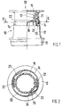
- Fig. 1
- teilweise in der Seitenansicht und teilweise im Längsschnitt einen Verschluß aus Verschlußunterteil und Schraubkappe in der gesicherten Verschlußstellung, jedoch bei ausgezogener Ausgießtülle, und
- Fig. 2
- einen Querschnitt durch den Verschluß entlang der Linie II-II der Fig. 1.
- Der Verschluß besteht aus einem Verschlußunterteil 10, das ein Basisteil 11, einen Balg 12 und eine Ausgießtülle 15 umfaßt. Das Basisteil 11 ist in eine Behälteröffnung einrastbar. In Fig. 1 ist der Balg 12 ausgezogen. Die Ausgießtülle 15 hat ein Außengewinde, auf das eine mit Innengewinde versehene Schraubkappe 20 auf- und abschraubbar ist. Die Schraubkappe 20 trägt das Innengewinde auf der Innenseite eines Kappenmantels 21. Die Ausgießtülle 15 ist im Auslieferzustand mittels einer Siegelplatte 16 verschlossen. Die Siegelplatte 16 kann mittels einer Grifflasche 17 aus der Ausgießtülle 15 herausgerissen werden.
- Der Kappenmantel 21 der Schraubkappe 20 läuft an der freien Stirnseite in zwei diametral zueinander stehende Rastlappen 22 aus, die sich über einen Teil des Umfanges der Schraubkappe 20 erstrecken, wie der Fig. 2 zu entnehmen ist. Der Übergang von der Ausgießtülle 15 zum Balg 12 ist als Absatz 13 ausgebildet. An dem Absatz 13 ist ein umlaufender Ringflansch 14 angeformt, der zum Kappenmantel 21 hin gerichtet ist und mit der Ausgießtülle 15 einen Aufnahmeraum 26 für die Rastlappen 22 der Schraubkappe 20 bildet, wenn diese auf die Ausgießtülle 15 aufgeschraubt ist. Der Ringflansch 14 trägt auf seiner Innenseite, d.h. den Rastlappen 22 zugekehrt, Rastnocken 23, welche in Aufschraubrichtung flache Anstiegsflanken 24 aufweisen. Die Anstiegsflanken 23 gehen in steile Rastflanken 25 über, hinter die die Rastlappen 22 der Schraubkappe 20 einrasten. Der Ringflansch 14 überdeckt die Rastlappen 22 teilweise, so daß ein Teil derselben noch einsehbar ist und so die Ansatzpunkte zum Fassen der Schraubkappe 20 markieren.
- Wird die Schraubkappe 20 im Bereich der Rastlappen 22 gefaßt und zusammengedrückt, dann werden die Rastlappen 22 außer Eingriff mit dem Rastnocken 23 an dem Ringflansch 14 angebracht. Die Schraubkappe 20 kann dann von der Ausgießtülle 15 abgeschraubt werden.
- Beim Aufschrauben der Schraubkappe 20 auf die Ausgießtülle 15 gleiten die Rastlappen 22 über die flachen Anstiegsflanken 24 der Rastnocken 23 an dem Ringflansch 14, stoßen beim Abschrauben jedoch an die steilen Rastflanken 25 der Rastnocken 23.
- Normalerweise genügt eine einzige Rastverbindung als Kindersicherung. Die beiden diametral angeordneten Rastverbindungen erhöhen jedoch die Sicherheit und erleichtern dem Erwachsenen die Aufhebung der Kindersicherung.
- In dem Ausführungsbeispiel nach den Fig. 1 und 2 ist ein Verschluß mit einem elastisch ausziehbaren Balg 12 gezeigt. Es ist jedoch möglich, die Kindersicherung an jedem beliebigen Verschluß zu verwenden. Insbesondere ist es denkbar, den Ringflansch 14 mit seinem Behälter selbst anzuordnen. Auch kann der Ringflansch 14 direkt an dem Verschlußunterteil 10 angeformt sein.
Claims (5)
- Verschluß für einen Behälter aus einem Verschlußunterteil und einer Schraubkappe, bei dem das Verschlußunterteil mittels eines Basisteils mit der Behälteröffnung verbindbar ist und eine Ausgießtülle aufweist, bei dem die Schraubkappe mit Kappenboden und mit Innengewinde versehenem Kappenmantel auf die mit Außengewinde versehene Ausgießtülle auf- und abschraubbar ist, bei dem die auf die Ausgießtülle aufgeschraubte Schraubkappe mittels Rastverbindungen gegen Abschrauben gesichert ist und bei dem durch Aufheben der Rastverbindung die Schraubkappe zum Abschrauben freigebbar ist,
dadurch gekennzeichnet,
daß der Kappenmantel (21) der Schraubkappe (20) im Bereich der freien Stirnseite mindestens in einen Rastlappen (22) ausläuft,
daß im Übergangsbereich zu der Ausgießtülle (15) an dem Verschluß ein zum Kappenmantel (21) hin abstehend angeformter Ringflansch (14) angeformt ist, der die Rastlappen (22) zumindest teilweise überdeckt, und
daß der Ringflansch (14) auf der den Rastlappen (22) zugekehrten Innenseite mit Rastnocken (23) versehen ist, die in Aufschraubrichtung eine flache Anstiegsflanke (24) aufweisen, welche in steile Rastflanken (25) übergehen und mit den Rastlappen (22) der Schraubkappe (20) Rastverbindungen bilden, welche durch radiales Auslenken der Rastlappen (22) aufhebbar sind. - Verschluß nach Anspruch 1,
dadurch gekennzeichnet,
daß die Ausgießtülle (15) mittels eines elastisch ausziehbaren Balges (12) mit dem Basisteil (11) des Verschlußunterteils (10) in Verbindung steht, und
daß der Ringflansch (14) im Übergangsbereich zwischen der Ausgießtülle (15) und dem Balg (12) angeordnet ist. - Verschluß nach Anspruch 1 oder 2,
dadurch gekennzeichnet,
daß am Kappenmantel (21) zwei Rastlappen (22) diametral angeordnet sind und
daß jedem Rastlappen (22) ein Rastnocken (23) an dem Verschlußteil (10) zugeordnet ist. - Verschluß nach einem der Ansprüche 1 bis 3,
dadurch gekennzeichnet,
daß die Ausgießtülle (15) über einen Absatz (13) in den Balg (12) übergeht und
daß der Ringflansch (14) an dem Absatz (13) konzentrisch zur Ausgießtülle (15) angeformt ist und mit dieser eine Ringaufnahme (26) für die Rastlappen (22) der Schraubkappe (20) bildet. - Verschluß nach einem der Ansprüche 1 bis 4,
dadurch gekennzeichnet,
daß die Rastlappen (22) dünnwandig ausgebildet und sich über einen Teil des Umfanges des Kappenmantels (21) erstrecken und radial leicht auslenkbar sind.
Applications Claiming Priority (2)
| Application Number | Priority Date | Filing Date | Title |
|---|---|---|---|
| DE4412195 | 1994-04-08 | ||
| DE4412195A DE4412195C1 (de) | 1994-04-08 | 1994-04-08 | Verschluß für einen Behälter aus einem Verschlußunterteil und einer Schraubkappe |
Publications (2)
| Publication Number | Publication Date |
|---|---|
| EP0676338A1 true EP0676338A1 (de) | 1995-10-11 |
| EP0676338B1 EP0676338B1 (de) | 1996-08-28 |
Family
ID=6514961
Family Applications (1)
| Application Number | Title | Priority Date | Filing Date |
|---|---|---|---|
| EP94114676A Expired - Lifetime EP0676338B1 (de) | 1994-04-08 | 1994-09-17 | Verschluss für einen Behälter aus einem Verschlussunterteil und einer Schraubkappe |
Country Status (9)
| Country | Link |
|---|---|
| US (1) | US5526947A (de) |
| EP (1) | EP0676338B1 (de) |
| AT (1) | ATE141885T1 (de) |
| CA (1) | CA2146602A1 (de) |
| DE (2) | DE4412195C1 (de) |
| DK (1) | DK0676338T3 (de) |
| ES (1) | ES2092369T3 (de) |
| TR (1) | TR28346A (de) |
| ZA (2) | ZA947433B (de) |
Cited By (1)
| Publication number | Priority date | Publication date | Assignee | Title |
|---|---|---|---|---|
| WO2001028868A3 (de) * | 1999-10-18 | 2002-04-11 | Alpla Werke | Mit einem flaschenbehältnis zusammenwirkende verschlusskappe |
Families Citing this family (4)
| Publication number | Priority date | Publication date | Assignee | Title |
|---|---|---|---|---|
| US5884815A (en) * | 1994-04-08 | 1999-03-23 | Heinrich Stolz Gmbh & Co. Kg | Safety closure for a container comprising a closure lower member and a screw cap |
| US6371316B1 (en) * | 2000-01-07 | 2002-04-16 | Kerr Group, Inc. | Child resistant closure and container with guarded flip-top |
| US7128233B2 (en) * | 2003-09-23 | 2006-10-31 | Jamie Hogan | Tamper-resistant container and methods |
| US20080095620A1 (en) * | 2006-10-20 | 2008-04-24 | Sun Microsystems, Inc. | Sync method for reducing fan noise |
Citations (4)
| Publication number | Priority date | Publication date | Assignee | Title |
|---|---|---|---|---|
| DE3625477A1 (de) * | 1986-07-28 | 1988-02-04 | Friedhoff & Mueller Fm Plast | Klappscharnierverschluss fuer flaschen oder aehnliche behaelter |
| EP0264152A2 (de) * | 1986-10-14 | 1988-04-20 | The Procter & Gamble Company | Zweiteilige Schraubkappe für Behälter |
| DE4139896A1 (de) * | 1991-12-04 | 1993-06-09 | Blechwarenfabrik Limburg Gmbh, 6250 Limburg, De | Kindergesichertes verschlusssystem |
| DE4209784A1 (de) * | 1992-03-26 | 1993-09-30 | Stolz Heinrich Gmbh | Verschluß für einen Behälter aus einem Verschlußunterteil und einer Schraubkappe |
Family Cites Families (7)
| Publication number | Priority date | Publication date | Assignee | Title |
|---|---|---|---|---|
| US3101856A (en) * | 1962-04-18 | 1963-08-27 | Jr Daniel S Whiteman | Bottle closure |
| US3623622A (en) * | 1970-07-13 | 1971-11-30 | Westhem Corp Ltd | Safety locking closure |
| US3984021A (en) * | 1972-09-11 | 1976-10-05 | Uhlig Gerhardt E | Safety closure container |
| US3941268A (en) * | 1975-01-08 | 1976-03-02 | Owens-Illinois, Inc. | Safety closure and container |
| DK147510C (da) * | 1982-07-01 | 1985-03-04 | Johannes Saemundur Palsson | Sikkerhedslukke med en lukkehaette, som kan saettes paa en beholderhalsdel, der har et spaerreorgan for lukkehaetten |
| US5078288A (en) * | 1990-10-30 | 1992-01-07 | Owens-Illinois Closure Inc. | Child resistant spout package |
| FR2676997B1 (fr) * | 1991-05-29 | 1993-08-27 | Novembal Sa | Bouchon-service a l'epreuve des enfants. |
-
1994
- 1994-04-08 DE DE4412195A patent/DE4412195C1/de not_active Expired - Fee Related
- 1994-09-17 ES ES94114676T patent/ES2092369T3/es not_active Expired - Lifetime
- 1994-09-17 AT AT94114676T patent/ATE141885T1/de active
- 1994-09-17 DE DE59400556T patent/DE59400556D1/de not_active Expired - Fee Related
- 1994-09-17 DK DK94114676.3T patent/DK0676338T3/da active
- 1994-09-17 EP EP94114676A patent/EP0676338B1/de not_active Expired - Lifetime
- 1994-09-23 ZA ZA947433A patent/ZA947433B/xx unknown
- 1994-10-07 TR TR01055/94A patent/TR28346A/xx unknown
-
1995
- 1995-04-04 US US08/368,472 patent/US5526947A/en not_active Expired - Lifetime
- 1995-04-07 ZA ZA952878A patent/ZA952878B/xx unknown
- 1995-04-07 CA CA002146602A patent/CA2146602A1/en not_active Abandoned
Patent Citations (4)
| Publication number | Priority date | Publication date | Assignee | Title |
|---|---|---|---|---|
| DE3625477A1 (de) * | 1986-07-28 | 1988-02-04 | Friedhoff & Mueller Fm Plast | Klappscharnierverschluss fuer flaschen oder aehnliche behaelter |
| EP0264152A2 (de) * | 1986-10-14 | 1988-04-20 | The Procter & Gamble Company | Zweiteilige Schraubkappe für Behälter |
| DE4139896A1 (de) * | 1991-12-04 | 1993-06-09 | Blechwarenfabrik Limburg Gmbh, 6250 Limburg, De | Kindergesichertes verschlusssystem |
| DE4209784A1 (de) * | 1992-03-26 | 1993-09-30 | Stolz Heinrich Gmbh | Verschluß für einen Behälter aus einem Verschlußunterteil und einer Schraubkappe |
Cited By (2)
| Publication number | Priority date | Publication date | Assignee | Title |
|---|---|---|---|---|
| WO2001028868A3 (de) * | 1999-10-18 | 2002-04-11 | Alpla Werke | Mit einem flaschenbehältnis zusammenwirkende verschlusskappe |
| US7100785B1 (en) | 1999-10-18 | 2006-09-05 | Alpla-Werke Alwin Lehner Gmbh & Co.Kg | Closure cap cooperating with a bottle type container |
Also Published As
| Publication number | Publication date |
|---|---|
| ZA947433B (en) | 1995-05-15 |
| DE59400556D1 (de) | 1996-10-02 |
| US5526947A (en) | 1996-06-18 |
| ES2092369T3 (es) | 1996-11-16 |
| ATE141885T1 (de) | 1996-09-15 |
| DE4412195C1 (de) | 1995-11-02 |
| TR28346A (tr) | 1996-05-23 |
| CA2146602A1 (en) | 1995-10-09 |
| EP0676338B1 (de) | 1996-08-28 |
| ZA952878B (en) | 1995-12-21 |
| DK0676338T3 (da) | 1996-12-02 |
Similar Documents
| Publication | Publication Date | Title |
|---|---|---|
| DE69833621T2 (de) | Kindersicherer Schraubverschluss | |
| EP0631559B1 (de) | Verschluss mit kindersicherung für einen behälter aus einem mit ausziehbarer ausgusstülle versehenen verschlussunterteil und einer schraubkappe | |
| DE2600410A1 (de) | Sicherheitsverschluss und behaelter | |
| EP0754150B1 (de) | Verschluss für einen behälter aus einem verschlussunterteil und einer schraubkappe | |
| CH647731A5 (de) | Flasche mit schraubverschluss und originalitaetssicherung. | |
| EP0676338B1 (de) | Verschluss für einen Behälter aus einem Verschlussunterteil und einer Schraubkappe | |
| CH664942A5 (de) | Verschlusskappe fuer einen sicherheitsbehaelter. | |
| DE2939095A1 (de) | Sicherheitsschraubverschluss | |
| EP0812288B1 (de) | Behälterverschluss | |
| EP0569897A1 (de) | Vorrichtung mit Kindersicherung zum Verschliessen von Behältern | |
| DE29501185U1 (de) | Verschluß für einen Behälter aus einem Verschlußunterteil und einer Schraubkappe | |
| EP0498954B1 (de) | Verschlusskappe für Kunststoffverschluss | |
| EP0562177B1 (de) | Verschluss mit einer Schraubkappe und einem Behälterstutzen oder einem mit dem Behälter verbindbaren Verschlussunterteil | |
| EP0805768A1 (de) | Verschluss mit ausgiesstülle | |
| DE4126015C1 (en) | Screw cap closure with warranty ring - which has axial expansion slit(s) between each two adjacent arresting teeth | |
| DE4211670C1 (de) | ||
| DE19947388B4 (de) | Behältnis zur Aufnahme eines Füllgutes mit einem Drehverschluss | |
| DE4330703C1 (de) | Schraubverschluß mit einer Schraubkappe und einem Sicherheits- und Garantiering | |
| WO2007017036A1 (de) | Kindergesicherter verschluss für behälter, insbesondere für kunststoffflaschen | |
| DE2314864C3 (de) | Sicherheits-Steckverschluß | |
| DE4417020C2 (de) | Verschlußkappe mit Dichtung | |
| DE2905947A1 (de) | Kinder-sicherheitsverschluss | |
| DE9408750U1 (de) | Schraubverschluß mit einer Kindersicherung | |
| DE9415731U1 (de) | Kindersichere Verschlussanordnung für Behälter | |
| DE9112284U1 (de) | Behälterverschluß |
Legal Events
| Date | Code | Title | Description |
|---|---|---|---|
| PUAI | Public reference made under article 153(3) epc to a published international application that has entered the european phase |
Free format text: ORIGINAL CODE: 0009012 |
|
| AK | Designated contracting states |
Kind code of ref document: A1 Designated state(s): AT BE CH DE DK ES FR GB GR IE IT LI LU MC NL PT SE |
|
| 17P | Request for examination filed |
Effective date: 19950921 |
|
| GRAG | Despatch of communication of intention to grant |
Free format text: ORIGINAL CODE: EPIDOS AGRA |
|
| GRAH | Despatch of communication of intention to grant a patent |
Free format text: ORIGINAL CODE: EPIDOS IGRA |
|
| 17Q | First examination report despatched |
Effective date: 19960215 |
|
| GRAH | Despatch of communication of intention to grant a patent |
Free format text: ORIGINAL CODE: EPIDOS IGRA |
|
| ITF | It: translation for a ep patent filed | ||
| GRAA | (expected) grant |
Free format text: ORIGINAL CODE: 0009210 |
|
| AK | Designated contracting states |
Kind code of ref document: B1 Designated state(s): AT BE CH DE DK ES FR GB GR IE IT LI LU MC NL PT SE |
|
| PG25 | Lapsed in a contracting state [announced via postgrant information from national office to epo] |
Ref country code: GR Free format text: LAPSE BECAUSE OF FAILURE TO SUBMIT A TRANSLATION OF THE DESCRIPTION OR TO PAY THE FEE WITHIN THE PRESCRIBED TIME-LIMIT Effective date: 19960828 |
|
| REF | Corresponds to: |
Ref document number: 141885 Country of ref document: AT Date of ref document: 19960915 Kind code of ref document: T |
|
| REG | Reference to a national code |
Ref country code: CH Ref legal event code: NV Representative=s name: PATENTANWALTSBUERO FELDMANN AG |
|
| PG25 | Lapsed in a contracting state [announced via postgrant information from national office to epo] |
Ref country code: LU Free format text: LAPSE BECAUSE OF NON-PAYMENT OF DUE FEES Effective date: 19960930 |
|
| REF | Corresponds to: |
Ref document number: 59400556 Country of ref document: DE Date of ref document: 19961002 |
|
| REG | Reference to a national code |
Ref country code: IE Ref legal event code: FG4D Free format text: 69643 |
|
| REG | Reference to a national code |
Ref country code: ES Ref legal event code: FG2A Ref document number: 2092369 Country of ref document: ES Kind code of ref document: T3 |
|
| PG25 | Lapsed in a contracting state [announced via postgrant information from national office to epo] |
Ref country code: SE Effective date: 19961128 |
|
| REG | Reference to a national code |
Ref country code: DK Ref legal event code: T3 |
|
| ET | Fr: translation filed | ||
| SC4A | Pt: translation is available |
Free format text: 960926 AVAILABILITY OF NATIONAL TRANSLATION |
|
| GBT | Gb: translation of ep patent filed (gb section 77(6)(a)/1977) |
Effective date: 19961129 |
|
| PG25 | Lapsed in a contracting state [announced via postgrant information from national office to epo] |
Ref country code: MC Effective date: 19970331 |
|
| REG | Reference to a national code |
Ref country code: IE Ref legal event code: FD4D Ref document number: 69643 Country of ref document: IE |
|
| PLBE | No opposition filed within time limit |
Free format text: ORIGINAL CODE: 0009261 |
|
| STAA | Information on the status of an ep patent application or granted ep patent |
Free format text: STATUS: NO OPPOSITION FILED WITHIN TIME LIMIT |
|
| 26N | No opposition filed | ||
| PGFP | Annual fee paid to national office [announced via postgrant information from national office to epo] |
Ref country code: PT Payment date: 19990429 Year of fee payment: 6 |
|
| PGFP | Annual fee paid to national office [announced via postgrant information from national office to epo] |
Ref country code: GB Payment date: 20000617 Year of fee payment: 7 |
|
| PGFP | Annual fee paid to national office [announced via postgrant information from national office to epo] |
Ref country code: ES Payment date: 20000704 Year of fee payment: 7 |
|
| PGFP | Annual fee paid to national office [announced via postgrant information from national office to epo] |
Ref country code: DK Payment date: 20000926 Year of fee payment: 7 |
|
| PGFP | Annual fee paid to national office [announced via postgrant information from national office to epo] |
Ref country code: FR Payment date: 20000929 Year of fee payment: 7 |
|
| PGFP | Annual fee paid to national office [announced via postgrant information from national office to epo] |
Ref country code: NL Payment date: 20000930 Year of fee payment: 7 Ref country code: AT Payment date: 20000930 Year of fee payment: 7 |
|
| PGFP | Annual fee paid to national office [announced via postgrant information from national office to epo] |
Ref country code: BE Payment date: 20001110 Year of fee payment: 7 |
|
| PGFP | Annual fee paid to national office [announced via postgrant information from national office to epo] |
Ref country code: CH Payment date: 20001219 Year of fee payment: 7 |
|
| PGFP | Annual fee paid to national office [announced via postgrant information from national office to epo] |
Ref country code: DE Payment date: 20010306 Year of fee payment: 7 |
|
| PG25 | Lapsed in a contracting state [announced via postgrant information from national office to epo] |
Ref country code: PT Free format text: LAPSE BECAUSE OF NON-PAYMENT OF DUE FEES Effective date: 20010331 |
|
| REG | Reference to a national code |
Ref country code: PT Ref legal event code: MM4A Free format text: LAPSE DUE TO NON-PAYMENT OF FEES Effective date: 20010331 |
|
| PG25 | Lapsed in a contracting state [announced via postgrant information from national office to epo] |
Ref country code: GB Free format text: LAPSE BECAUSE OF NON-PAYMENT OF DUE FEES Effective date: 20010917 Ref country code: DK Free format text: LAPSE BECAUSE OF NON-PAYMENT OF DUE FEES Effective date: 20010917 Ref country code: AT Free format text: LAPSE BECAUSE OF NON-PAYMENT OF DUE FEES Effective date: 20010917 |
|
| PG25 | Lapsed in a contracting state [announced via postgrant information from national office to epo] |
Ref country code: ES Free format text: LAPSE BECAUSE OF NON-PAYMENT OF DUE FEES Effective date: 20010918 |
|
| PG25 | Lapsed in a contracting state [announced via postgrant information from national office to epo] |
Ref country code: LI Free format text: LAPSE BECAUSE OF NON-PAYMENT OF DUE FEES Effective date: 20010930 Ref country code: CH Free format text: LAPSE BECAUSE OF NON-PAYMENT OF DUE FEES Effective date: 20010930 Ref country code: BE Free format text: LAPSE BECAUSE OF NON-PAYMENT OF DUE FEES Effective date: 20010930 |
|
| REG | Reference to a national code |
Ref country code: GB Ref legal event code: IF02 |
|
| BERE | Be: lapsed |
Owner name: HEINRICH STOLZ G.M.B.H. & CO. K.G. Effective date: 20010930 |
|
| PG25 | Lapsed in a contracting state [announced via postgrant information from national office to epo] |
Ref country code: NL Free format text: LAPSE BECAUSE OF NON-PAYMENT OF DUE FEES Effective date: 20020401 |
|
| PG25 | Lapsed in a contracting state [announced via postgrant information from national office to epo] |
Ref country code: DE Free format text: LAPSE BECAUSE OF NON-PAYMENT OF DUE FEES Effective date: 20020501 |
|
| GBPC | Gb: european patent ceased through non-payment of renewal fee |
Effective date: 20010917 |
|
| REG | Reference to a national code |
Ref country code: CH Ref legal event code: PL |
|
| PG25 | Lapsed in a contracting state [announced via postgrant information from national office to epo] |
Ref country code: FR Free format text: LAPSE BECAUSE OF NON-PAYMENT OF DUE FEES Effective date: 20020531 |
|
| NLV4 | Nl: lapsed or anulled due to non-payment of the annual fee |
Effective date: 20020401 |
|
| REG | Reference to a national code |
Ref country code: DK Ref legal event code: EBP |
|
| REG | Reference to a national code |
Ref country code: FR Ref legal event code: ST |
|
| NLV4 | Nl: lapsed or anulled due to non-payment of the annual fee |
Effective date: 20020401 |
|
| REG | Reference to a national code |
Ref country code: ES Ref legal event code: FD2A Effective date: 20021011 |
|
| PG25 | Lapsed in a contracting state [announced via postgrant information from national office to epo] |
Ref country code: IT Free format text: LAPSE BECAUSE OF NON-PAYMENT OF DUE FEES;WARNING: LAPSES OF ITALIAN PATENTS WITH EFFECTIVE DATE BEFORE 2007 MAY HAVE OCCURRED AT ANY TIME BEFORE 2007. THE CORRECT EFFECTIVE DATE MAY BE DIFFERENT FROM THE ONE RECORDED. Effective date: 20050917 |