EP0676531B1 - Gleitschalung für Tunnelwandungen - Google Patents
Gleitschalung für Tunnelwandungen Download PDFInfo
- Publication number
- EP0676531B1 EP0676531B1 EP95102979A EP95102979A EP0676531B1 EP 0676531 B1 EP0676531 B1 EP 0676531B1 EP 95102979 A EP95102979 A EP 95102979A EP 95102979 A EP95102979 A EP 95102979A EP 0676531 B1 EP0676531 B1 EP 0676531B1
- Authority
- EP
- European Patent Office
- Prior art keywords
- support device
- wall
- sliding surface
- vibration element
- layer
- Prior art date
- Legal status (The legal status is an assumption and is not a legal conclusion. Google has not performed a legal analysis and makes no representation as to the accuracy of the status listed.)
- Expired - Lifetime
Links
Images


Classifications
-
- E—FIXED CONSTRUCTIONS
- E21—EARTH OR ROCK DRILLING; MINING
- E21D—SHAFTS; TUNNELS; GALLERIES; LARGE UNDERGROUND CHAMBERS
- E21D11/00—Lining tunnels, galleries or other underground cavities, e.g. large underground chambers; Linings therefor; Making such linings in situ, e.g. by assembling
- E21D11/04—Lining with building materials
- E21D11/10—Lining with building materials with concrete cast in situ; Shuttering also lost shutterings, e.g. made of blocks, of metal plates or other equipment adapted therefor
- E21D11/105—Transport or application of concrete specially adapted for the lining of tunnels or galleries ; Backfilling the space between main building element and the surrounding rock, e.g. with concrete
Definitions
- the invention relates to a layer capable of setting during the application Formwork slidably movable along the processing direction, e.g. at Concreting work, especially on tunnel walls, is used.
- a sliding formwork corresponding to the preamble of claim 1 is known from EP-A-0 215 243 or DE-C-3 533 476 by the same applicant.
- the object is achieved in that the vibration element is an oscillation in the direction of sinking of the wall, in particular tunnel longitudinal direction, so that the entrainment of mixture adhering to the support surface is avoided.
- the sliding formwork can advantageously be provided with a lateral support device Claim 4 be provided to prevent the applied setable Mix after application and before substantial consolidation on the side can escape.
- the lateral support device is therefore suitably flexibly mounted and by means of a pressing device, e.g. a spring, elastic to the wall pressable.
- This lateral support device can also advantageously be equipped with a Be provided vibration element, in the direction of the wall to or from this acts away, i.e. in the radial direction of a tunnel.
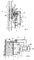
- Fig. 1 shows a side view of a sliding formwork, whose acting as a support surface Sliding surface 5, as basically described in DE-C1-35 33 476, there Fig. 6, with the Progress of a layer 1 to be sprayed on in the processing direction 17 according to the Arrow is movable. This movement is advantageously carried out continuously.
- the device for spraying one consists of a capable of setting curable mixture of binder additive and liquid existing Layer 1 on a wall 2, like that of a tunnel, the one to be sprayed on Mixing leading flexible pressure line 3, from whose on the wall 2nd directed and movable at a distance over the wall 2 end 4, the appropriate is formed by a spray nozzle 20, which exits the mixture to be sprayed and onto which Wall 2 arrives.
- the sliding surface 5 In one corresponding to the thickness of the layer 1 to be sprayed on Distance from the wall 2 is the sliding surface 5 forming the support surface according to Art a formwork is provided for the layer 1 to be sprayed on, the sliding surface 5 as mentioned, following the movements of the outlet end 4 of the pressure line 3 is movably arranged.
- the sliding surface 5 is supported by a support structure 13 and has a movement drive 8 to the sliding surface 5 according to the Movement of the outlet end 4 of the pressure line 3 the basic course of the Wall 2 still to lead, approximately along one in Fig. 1 by a two-dot chain line marked guide frame 23 (see. Fig. 5).
- the Movement drive 8 also in a manner not shown via pivotable arms of an independent drive device, e.g.
- the sliding surface 5 has one Support structure 13, which is associated with the motion drive 8 in a suitable manner.
- the support structure 13 can be connected to the pressure line 3 or the spray nozzle 20 be arranged mechanically coupled and on a common sprayer to be appropriate. It is also a movable attachment to the breakout profiles or on the wall 2 conceivable.
- the support structure 13 in essentially of a connection carrier 15 and one connected to the latter Support arm 16.
- the sliding surface 5 is on adapted to the wall curvatures and can have a leading surface at the front end 18 exhibit.
- the width and / or the length of the sliding surface 5 results from the practical conditions and is particularly adapted to the mixture used.
- a schematically represented reinforcement 22 can also be inserted into the manufactured layer 1 be inserted.
- the sliding surface 5 carries a schematic on its side facing away from the wall 2 Shown vibration element 6, which is in the area of the freshly applied mixture layer 1 mechanically high-frequency vibrations in the order of magnitude up to to 9000 Hz in the sinking direction, i.e. in the longitudinal direction of the tunnel corresponding to the Double arrow 36 in Fig. 5 exercises.
- vibration element 6 which is in the area of the freshly applied mixture layer 1 mechanically high-frequency vibrations in the order of magnitude up to to 9000 Hz in the sinking direction, i.e. in the longitudinal direction of the tunnel corresponding to the Double arrow 36 in Fig. 5 exercises.
- the support structure 13 has a support plate 14 which via support bracket 12 with the side of the sliding surface 5 facing away from the wall 2 is connected, with the vibration element 6 also in the space thus formed is provided.
- the support plate 14 is resilient via a schematically shown flexible suspension 19 with the connection carrier 15 of the supporting structure 13 connected. This creates a constant pressure against the outside pointing surface 9 of the layer 1 exercised and on the other hand safely avoided that the mechanical vibrations triggered by the vibration element 6 on the overlap other construction elements of the spraying device.
- FIG. 2 differs from that of FIG. 1 in essentially by a multi-unit design of the sliding surface 5.
- the front element 24 of the sliding surface 5 has the vibration element 6.
- Die different members 24 and 25 of the sliding surface 5 are associated with resilient flexible applications 27 and 28 connected to the connection carrier 15. By appropriate adjustment of the respective distance between these resilient suspensions 27, 28, an individual curvature of the entire sliding surface 5 can be adapted achieve the course of the wall 2.
- Fig. 3 shows a side view of a first embodiment of a sliding formwork, such as 1, with a lateral support device 30, which is used as side formwork works.
- this lateral support device 30 consists of a rotatable mounted disc 31, which resiliently on a resilient support 35 mounted pendulum arm 33 is attached, the spring-loaded pendulum arm 33 on the Support structure 13 is mounted.
- the pendulum arm 33 By this pendulum arm 33, the disc 31 is on pressed the wall 2 that it rolls along the wall 2 and the Unevenness of the wall 2 can follow.
- the side Support device as shown in Fig. 3, have a side sliding formwork 32.
- the Sliding formwork can be particularly advantageous when lining tunnel walls be used.
- the sliding formwork moves in a circular or spiral manner around the tunnel wall. While applying the first layer to each of the Both sides of the sliding formwork should be fitted with a side formwork Application of each subsequent layer adjacent to the first-mentioned layer lateral escape of the applied mixture through the already applied adjacent layer prevented on one side, so that for the second and each additional layer Such side formwork is only to be provided on one side of the sliding formwork.
- FIG. 4 shows another embodiment of a lateral support device 30.
- Two overlapping disks 31 1 and 31 2 are connected to a telescopic arm 34 directly or via a pendulum arm 33.
- This arrangement of telescopic arm 34 and / or pendulum arm 33 brings about an elastic pressing of the disks 31 1 and 31 2 against the wall 2.
- an additional sliding formwork such as the sliding formwork 32 in FIG. 3, can be dispensed with. It is conceivable to arrange further disks overlapping and / or entangled one behind the other in order to increase the effective length of the lateral support device 30.
- the elastically mounted disks 31 or 31 1 and 31 2 have the advantage of being able to roll over them and, by reaching into the fields of the reinforcement mats, the gap between them and the wall 2 nevertheless to be able to close largely.
- the sliding formwork can be along a guide frame 23 be performed.
- the Guide frame 23 advantageously designed according to the tunnel profile.
- a side surface 11 (FIG. 5) is formed from the mixture.
- the side support 30 does not necessarily have to be attached to the supporting structure 13 in the area of the connecting support 15, but can also in the region of the guide frame 23 with the support structure 13 be connected via a telescopic arm 34.
- the latter arrangement allows a special one simple retrofitting if the side surface 11 of layer 1 is not as in FIG. 5 shown above, but below (when shown in Fig. 5) should be provided.
- the desired uniform surface 9 free of tearing of the set Layer 1 can therefore be achieved.
Landscapes
- Engineering & Computer Science (AREA)
- Structural Engineering (AREA)
- Architecture (AREA)
- Mining & Mineral Resources (AREA)
- Civil Engineering (AREA)
- Life Sciences & Earth Sciences (AREA)
- General Life Sciences & Earth Sciences (AREA)
- Geochemistry & Mineralogy (AREA)
- Geology (AREA)
- Lining And Supports For Tunnels (AREA)
- Forms Removed On Construction Sites Or Auxiliary Members Thereof (AREA)
Description
- Fig. 1
- schematisch ein Ausführungsbeispiel einer Gleitschalung mit einem Vibrationselement gemäß der Erfindung;
- Fig. 2
- ähnlich Fig. 1 eine mehrgliedrige Ausbildung einer Gleitschalung;
- Fig. 3
- eine mit einer seitlichen Stützvorrichtung versehene Gleitschalung gemäß der Erfindung;
- Fig. 4
- eine andere Ausführungsform einer seitlichen Stützvorrichtung;
- Fig. 5
- eine weitere Ausführungsform der Halterung einer seitlichen Stützvorrichtung.
Claims (12)
- Stützvorrichtung zum Stützen einer aus einer abbindefähigen Mischung bestehenden und auf eine Wandung (2) aufgebrachten Schicht (1) in noch nicht selbsttragend abgebundenen Zustand der Mischung,
mit einer Tragkonstruktion (13) verbundenen Gleitfläche (5), die im Bereich ihrer Flächenausdehnung eine schalungsähnliche Stützfläche bietet,
wobei mit der Gleitfläche (5), von der Wandung (2) abgewandt, mindestens ein Vibrationselement (6) verbunden ist, das über die Gleitfläche (5) auf die aufgebrachte Schicht (1) einwirkt dadurch gekennzeichnet,
daß das Vibrationselement (6) eine Schwingung in Abteufrichtung der Wandung (2), insbesondere Tunnellängsrichtung, ausübt, so daß die Mitnahme von an der Stützfläche anhaftender Mischung vermieden wird. - Stützvorrichtung nach Anspruch 1,
dadurch gekennzeichnet,
daß das Vibrationselement (6) hochfrequente mechanische Schwinungen der Gleitfläche (5) erreicht. - Stützvorrichtung nach Anspruch 2,
gekennzeichnet durch Frequenzen in der Größenordnung von bis 9000 Hz. - Stützvorrichtung nach einem der Ansprüche 1 bis 3,
gekennzeichnet durch eine flexible gelagerte schalungsähnliche seitliche Stützvorrichtung (30), die die abbindefähige Mischung zumindest im Bereich einer Seitenlinie der Gleitfläche (5) zwischen der Wandung (2) und dieser abstützt, gegebenenfalls mit einer Andrückvorrichtung (35), die die seitliche Stützvorrichtung (30) elastisch den Unebenheiten der Wandung (2) folgend an diese andrückt, so daß der Bereich zwischen der Gleitfläche (5) und der Wandung (2) entlang der zumindest einen Seitenlinie der Gleitfläche (5) im wesentlichen vollständig geschlossen wird. - Stützvorrichtung nach Anspruch 4,
dadurch gekennzeichnet,
daß ein weiteres Vibrationselement (7) auf die seitliche Stützvorrichtung (30) unabhängig von der Gleitfläche (5) einwirkt. - Stützvorrichtung nach Anspruch 4 oder 5,
dadurch gekennzeichnet,
daß das weitere Vibrationselement (7) eine Schwingung in Richtung auf die Wandung (2) ausübt. - Stützvorrichtung nach einem der Ansprüch 4 bis 6,
dadurch gekennzeichnet,
daß die seitliche Stützvorrichtung (30) mittels einer oder mehrerer drehbarer Scheiben (31;311,312) gebildet ist, die längs der Wandung (2) rollen. - Stützvorrichtung nach Anspruch 7,
dadurch gekennzeichnet,
daß mehrere überlappend und/oder verschränkt angeordnete Scheiben (311,312) vorgesehen sind. - Stützvorrichtung nach einem der Ansprüche 4 bis 8,
dadurch gekennzeichnet,
daß die seitliche Stützvorrichtung (30) mittels gefederter Teleskop- und/oder Pendelarme (34,33) an der Tragkonstruktion (13) befestigt ist. - Stützvorrichtung nach einem der Ansprüche 1 bis 9,
gekennzeichnet durch eine mehrgliedrige Ausbildung der Gleitfläche (5), wobei die Glieder (24,25) in Aufbringrichtung der Schicht (1) aufeinanderfolgen. - Stützvorrichtung nach Anspruch 10,
dadurch gekennzeichnet,
daß das Vibrationselement (6) zumindest dem Glied (24) der Gleitfläche (5) zugeordnet ist, das in Aufbringrichtung der Schicht (1) vorne ist. - Vorrichtung nach einem der Ansprüche 1 bis 11,
dadurch gekennzeichnet,
daß das Vibrationselement (6) auf der Gleitfläche (5) aufgebracht ist und diese gegen die Tragkonstruktion (13) federnd nachgiebig (19) abgestützt ist.
Applications Claiming Priority (2)
| Application Number | Priority Date | Filing Date | Title |
|---|---|---|---|
| DE4411976A DE4411976A1 (de) | 1994-04-07 | 1994-04-07 | Gleitschalung |
| DE4411976 | 1994-04-07 |
Publications (2)
| Publication Number | Publication Date |
|---|---|
| EP0676531A1 EP0676531A1 (de) | 1995-10-11 |
| EP0676531B1 true EP0676531B1 (de) | 1999-10-13 |
Family
ID=6514821
Family Applications (1)
| Application Number | Title | Priority Date | Filing Date |
|---|---|---|---|
| EP95102979A Expired - Lifetime EP0676531B1 (de) | 1994-04-07 | 1995-03-02 | Gleitschalung für Tunnelwandungen |
Country Status (3)
| Country | Link |
|---|---|
| EP (1) | EP0676531B1 (de) |
| AT (1) | ATE185609T1 (de) |
| DE (2) | DE4411976A1 (de) |
Families Citing this family (4)
| Publication number | Priority date | Publication date | Assignee | Title |
|---|---|---|---|---|
| AT504264B1 (de) * | 2006-07-25 | 2012-07-15 | Porr Tunnelbau Gmbh | Vorrichtung und verfahren zum auftragen einer abbindbaren schicht auf wandungen von bauteilen |
| CN109538250B (zh) * | 2019-01-28 | 2023-09-15 | 中南大学 | 用于隧道初支带模喷射混凝土快速施工的装置及方法 |
| CN114320364B (zh) * | 2021-12-21 | 2024-07-30 | 洛阳中铁强力机械有限公司 | 一种隧道喷锚辅助台车 |
| CN114294020A (zh) * | 2021-12-31 | 2022-04-08 | 北京市政建设集团有限责任公司 | 一种边导洞回填施工方法 |
Family Cites Families (4)
| Publication number | Priority date | Publication date | Assignee | Title |
|---|---|---|---|---|
| CH613015A5 (en) * | 1976-07-15 | 1979-08-31 | Spribag Ag | Mobile apparatus for applying shotcrete to walls |
| DE3037790A1 (de) * | 1980-10-07 | 1982-05-13 | Gewerkschaft Eisenhütte Westfalia, 4670 Lünen | Vorrichtung zum auskleiden eines tunnels, einer unterirdischen strecke o. dgl. mit erhaertenden stoffen |
| DE3533476C1 (de) * | 1985-09-19 | 1986-06-12 | Philipp Holzmann Ag, 6000 Frankfurt | Vorrichtung zum Aufspritzen einer abbindefaehigen Schicht auf Wandungen |
| DE4316116A1 (de) * | 1993-05-13 | 1994-11-17 | Holzmann Philipp Ag | Rollschalung |
-
1994
- 1994-04-07 DE DE4411976A patent/DE4411976A1/de not_active Ceased
-
1995
- 1995-03-02 AT AT95102979T patent/ATE185609T1/de not_active IP Right Cessation
- 1995-03-02 DE DE59507017T patent/DE59507017D1/de not_active Expired - Fee Related
- 1995-03-02 EP EP95102979A patent/EP0676531B1/de not_active Expired - Lifetime
Also Published As
| Publication number | Publication date |
|---|---|
| DE59507017D1 (de) | 1999-11-18 |
| ATE185609T1 (de) | 1999-10-15 |
| DE4411976A1 (de) | 1995-10-12 |
| EP0676531A1 (de) | 1995-10-11 |
Similar Documents
| Publication | Publication Date | Title |
|---|---|---|
| AT403812B (de) | Maschine zum anpressen von schwellenankern | |
| EP0676531B1 (de) | Gleitschalung für Tunnelwandungen | |
| DE3533476C1 (de) | Vorrichtung zum Aufspritzen einer abbindefaehigen Schicht auf Wandungen | |
| DE2610519C2 (de) | Gleisstopfmaschine | |
| CH646490A5 (de) | Verfahren und vorrichtung zum einbringen einer betonauskleidung beim vortrieb unterirdischer hohlraeume. | |
| CH677076A5 (de) | ||
| DE2612169C3 (de) | Steuervorrichtung für einen Messerschild | |
| DE69001973T2 (de) | Ausziehbare Bohle zum Verdichten und Fertigen von Strassendeckenschichten mit Spritzvorrichtung für flüssiges Bindemittel. | |
| DE69108348T2 (de) | Verfahren zum Aufbringen von Bitumen mit reduzierter Geschwindigkeit, Vorrichtung zum Durchführen desselben und Vorrichtung mit dieser Vorrichtung. | |
| DE4403243A1 (de) | Spritzvorrichtung zum Aufspritzen eines flüssigen Bindemittels | |
| DE19903638A1 (de) | Vorrichtung zum Glätten einer Betonbelagsoberfläche | |
| EP0624713B1 (de) | Rollschalung | |
| DE3037790C2 (de) | ||
| DE4014098C2 (de) | ||
| EP0728241B1 (de) | Auftragswerk zum direkten oder indirekten auftragen eines flüssigen oder pastösen mediums auf eine laufende materialbahn | |
| DE3132870A1 (de) | Gleisnivellierstopf- und richtmaschine mit stabilisationsaggregat | |
| DE2445383C2 (de) | Kletterschalung | |
| AT412735B (de) | Vorrichtung zum aufbringen eines bindemittels für einen asphaltbelag auf einer verkehrsfläche | |
| DE2621421C2 (de) | Drehmomentenabstützung für einen Vortriebsschild | |
| EP0022121A1 (de) | Stütz- und Führungsgerüst für Stranggiessanlagen | |
| DE3129060A1 (de) | Verfahren und kanalbaulaengsmaschine zum einbauen von auskleidungen in wasserkanaelen, z.b. in bewaesserungskanaelen | |
| DE2727932B1 (de) | Vorrichtung zur stufenlosen Verstellung der Arbeitsbreiten von Strassenfertigern | |
| DE2439788A1 (de) | Selbstfahrende strassenwalze | |
| EP0338242B1 (de) | Vorrichtung zur Herstellung einer in Einzelfelder unterteilten Betonschicht | |
| DE2754103C3 (de) | An einem Schienenfahrzeug vorgesehene Vorrichtung zum Verteilen und Profilieren des Bettungsschotters eines Gleises |
Legal Events
| Date | Code | Title | Description |
|---|---|---|---|
| PUAI | Public reference made under article 153(3) epc to a published international application that has entered the european phase |
Free format text: ORIGINAL CODE: 0009012 |
|
| AK | Designated contracting states |
Kind code of ref document: A1 Designated state(s): AT BE CH DE DK ES FR GB GR IE IT LI LU MC NL PT SE |
|
| 17P | Request for examination filed |
Effective date: 19960206 |
|
| GRAG | Despatch of communication of intention to grant |
Free format text: ORIGINAL CODE: EPIDOS AGRA |
|
| 17Q | First examination report despatched |
Effective date: 19981211 |
|
| GRAG | Despatch of communication of intention to grant |
Free format text: ORIGINAL CODE: EPIDOS AGRA |
|
| GRAH | Despatch of communication of intention to grant a patent |
Free format text: ORIGINAL CODE: EPIDOS IGRA |
|
| GRAH | Despatch of communication of intention to grant a patent |
Free format text: ORIGINAL CODE: EPIDOS IGRA |
|
| GRAA | (expected) grant |
Free format text: ORIGINAL CODE: 0009210 |
|
| AK | Designated contracting states |
Kind code of ref document: B1 Designated state(s): AT BE CH DE DK ES FR GB GR IE IT LI LU MC NL PT SE |
|
| PG25 | Lapsed in a contracting state [announced via postgrant information from national office to epo] |
Ref country code: SE Free format text: THE PATENT HAS BEEN ANNULLED BY A DECISION OF A NATIONAL AUTHORITY Effective date: 19991013 Ref country code: NL Free format text: LAPSE BECAUSE OF FAILURE TO SUBMIT A TRANSLATION OF THE DESCRIPTION OR TO PAY THE FEE WITHIN THE PRESCRIBED TIME-LIMIT Effective date: 19991013 Ref country code: IT Free format text: LAPSE BECAUSE OF FAILURE TO SUBMIT A TRANSLATION OF THE DESCRIPTION OR TO PAY THE FEE WITHIN THE PRESCRIBED TIME-LIMIT;WARNING: LAPSES OF ITALIAN PATENTS WITH EFFECTIVE DATE BEFORE 2007 MAY HAVE OCCURRED AT ANY TIME BEFORE 2007. THE CORRECT EFFECTIVE DATE MAY BE DIFFERENT FROM THE ONE RECORDED. Effective date: 19991013 Ref country code: GR Free format text: LAPSE BECAUSE OF NON-PAYMENT OF DUE FEES Effective date: 19991013 Ref country code: GB Free format text: LAPSE BECAUSE OF FAILURE TO SUBMIT A TRANSLATION OF THE DESCRIPTION OR TO PAY THE FEE WITHIN THE PRESCRIBED TIME-LIMIT Effective date: 19991013 Ref country code: FR Free format text: LAPSE BECAUSE OF FAILURE TO SUBMIT A TRANSLATION OF THE DESCRIPTION OR TO PAY THE FEE WITHIN THE PRESCRIBED TIME-LIMIT Effective date: 19991013 Ref country code: ES Free format text: THE PATENT HAS BEEN ANNULLED BY A DECISION OF A NATIONAL AUTHORITY Effective date: 19991013 |
|
| REF | Corresponds to: |
Ref document number: 185609 Country of ref document: AT Date of ref document: 19991015 Kind code of ref document: T |
|
| REG | Reference to a national code |
Ref country code: CH Ref legal event code: EP |
|
| REF | Corresponds to: |
Ref document number: 59507017 Country of ref document: DE Date of ref document: 19991118 |
|
| PG25 | Lapsed in a contracting state [announced via postgrant information from national office to epo] |
Ref country code: PT Free format text: LAPSE BECAUSE OF FAILURE TO SUBMIT A TRANSLATION OF THE DESCRIPTION OR TO PAY THE FEE WITHIN THE PRESCRIBED TIME-LIMIT Effective date: 20000113 Ref country code: DK Free format text: LAPSE BECAUSE OF FAILURE TO SUBMIT A TRANSLATION OF THE DESCRIPTION OR TO PAY THE FEE WITHIN THE PRESCRIBED TIME-LIMIT Effective date: 20000113 |
|
| REG | Reference to a national code |
Ref country code: IE Ref legal event code: FG4D Free format text: GERMAN |
|
| PG25 | Lapsed in a contracting state [announced via postgrant information from national office to epo] |
Ref country code: LU Free format text: LAPSE BECAUSE OF NON-PAYMENT OF DUE FEES Effective date: 20000302 Ref country code: AT Free format text: LAPSE BECAUSE OF NON-PAYMENT OF DUE FEES Effective date: 20000302 |
|
| EN | Fr: translation not filed | ||
| PG25 | Lapsed in a contracting state [announced via postgrant information from national office to epo] |
Ref country code: LI Free format text: LAPSE BECAUSE OF NON-PAYMENT OF DUE FEES Effective date: 20000331 Ref country code: CH Free format text: LAPSE BECAUSE OF NON-PAYMENT OF DUE FEES Effective date: 20000331 Ref country code: BE Free format text: LAPSE BECAUSE OF NON-PAYMENT OF DUE FEES Effective date: 20000331 |
|
| NLV1 | Nl: lapsed or annulled due to failure to fulfill the requirements of art. 29p and 29m of the patents act | ||
| GBV | Gb: ep patent (uk) treated as always having been void in accordance with gb section 77(7)/1977 [no translation filed] |
Effective date: 19991013 |
|
| PG25 | Lapsed in a contracting state [announced via postgrant information from national office to epo] |
Ref country code: IE Free format text: LAPSE BECAUSE OF NON-PAYMENT OF DUE FEES Effective date: 20000621 |
|
| REG | Reference to a national code |
Ref country code: IE Ref legal event code: FD4D |
|
| PLBE | No opposition filed within time limit |
Free format text: ORIGINAL CODE: 0009261 |
|
| STAA | Information on the status of an ep patent application or granted ep patent |
Free format text: STATUS: NO OPPOSITION FILED WITHIN TIME LIMIT |
|
| 26N | No opposition filed | ||
| BERE | Be: lapsed |
Owner name: PHILIPP HOLZMANN A.G. Effective date: 20000331 |
|
| PG25 | Lapsed in a contracting state [announced via postgrant information from national office to epo] |
Ref country code: MC Free format text: LAPSE BECAUSE OF NON-PAYMENT OF DUE FEES Effective date: 20000930 |
|
| REG | Reference to a national code |
Ref country code: CH Ref legal event code: PL |
|
| PGFP | Annual fee paid to national office [announced via postgrant information from national office to epo] |
Ref country code: DE Payment date: 20020222 Year of fee payment: 8 |
|
| PG25 | Lapsed in a contracting state [announced via postgrant information from national office to epo] |
Ref country code: DE Free format text: LAPSE BECAUSE OF NON-PAYMENT OF DUE FEES Effective date: 20051124 |