EP0676553A2 - Palier à contact de roulement - Google Patents
Palier à contact de roulement Download PDFInfo
- Publication number
- EP0676553A2 EP0676553A2 EP95102046A EP95102046A EP0676553A2 EP 0676553 A2 EP0676553 A2 EP 0676553A2 EP 95102046 A EP95102046 A EP 95102046A EP 95102046 A EP95102046 A EP 95102046A EP 0676553 A2 EP0676553 A2 EP 0676553A2
- Authority
- EP
- European Patent Office
- Prior art keywords
- rolling bearing
- raceways
- bearing according
- rolling
- component
- Prior art date
- Legal status (The legal status is an assumption and is not a legal conclusion. Google has not performed a legal analysis and makes no representation as to the accuracy of the status listed.)
- Granted
Links
- 238000005096 rolling process Methods 0.000 title claims description 36
- 238000001746 injection moulding Methods 0.000 claims abstract description 17
- 239000004033 plastic Substances 0.000 claims abstract description 14
- 229920003023 plastic Polymers 0.000 claims abstract description 14
- 229910052751 metal Inorganic materials 0.000 claims abstract description 10
- 239000002184 metal Substances 0.000 claims abstract description 10
- 239000000843 powder Substances 0.000 claims abstract description 7
- 239000000203 mixture Substances 0.000 claims abstract description 6
- 239000008187 granular material Substances 0.000 claims abstract description 3
- 238000000034 method Methods 0.000 claims description 9
- 230000004087 circulation Effects 0.000 claims description 8
- 238000004519 manufacturing process Methods 0.000 claims description 6
- 238000002347 injection Methods 0.000 claims description 4
- 239000007924 injection Substances 0.000 claims description 4
- 238000010438 heat treatment Methods 0.000 claims description 3
- 238000005507 spraying Methods 0.000 claims description 3
- 239000000126 substance Substances 0.000 claims description 3
- 238000006073 displacement reaction Methods 0.000 claims description 2
- 239000007769 metal material Substances 0.000 claims description 2
- 239000000463 material Substances 0.000 abstract description 7
- 238000000465 moulding Methods 0.000 abstract 1
- 239000011230 binding agent Substances 0.000 description 3
- 230000001133 acceleration Effects 0.000 description 2
- 238000005516 engineering process Methods 0.000 description 2
- 238000005245 sintering Methods 0.000 description 2
- 229910000838 Al alloy Inorganic materials 0.000 description 1
- 229910001111 Fine metal Inorganic materials 0.000 description 1
- 229910000831 Steel Inorganic materials 0.000 description 1
- 229910001297 Zn alloy Inorganic materials 0.000 description 1
- 239000000654 additive Substances 0.000 description 1
- 229910045601 alloy Inorganic materials 0.000 description 1
- 239000000956 alloy Substances 0.000 description 1
- XAGFODPZIPBFFR-UHFFFAOYSA-N aluminium Chemical compound [Al] XAGFODPZIPBFFR-UHFFFAOYSA-N 0.000 description 1
- 238000002144 chemical decomposition reaction Methods 0.000 description 1
- 238000010276 construction Methods 0.000 description 1
- 238000000227 grinding Methods 0.000 description 1
- 238000005461 lubrication Methods 0.000 description 1
- 238000003754 machining Methods 0.000 description 1
- 239000002991 molded plastic Substances 0.000 description 1
- 238000004663 powder metallurgy Methods 0.000 description 1
- 230000001681 protective effect Effects 0.000 description 1
- 230000000284 resting effect Effects 0.000 description 1
- 238000007493 shaping process Methods 0.000 description 1
- 239000011343 solid material Substances 0.000 description 1
- 239000007858 starting material Substances 0.000 description 1
- 239000010959 steel Substances 0.000 description 1
- 238000003860 storage Methods 0.000 description 1
- 238000005979 thermal decomposition reaction Methods 0.000 description 1
- 239000001993 wax Substances 0.000 description 1
Images
Classifications
-
- F—MECHANICAL ENGINEERING; LIGHTING; HEATING; WEAPONS; BLASTING
- F16—ENGINEERING ELEMENTS AND UNITS; GENERAL MEASURES FOR PRODUCING AND MAINTAINING EFFECTIVE FUNCTIONING OF MACHINES OR INSTALLATIONS; THERMAL INSULATION IN GENERAL
- F16C—SHAFTS; FLEXIBLE SHAFTS; ELEMENTS OR CRANKSHAFT MECHANISMS; ROTARY BODIES OTHER THAN GEARING ELEMENTS; BEARINGS
- F16C29/00—Bearings for parts moving only linearly
- F16C29/04—Ball or roller bearings
- F16C29/06—Ball or roller bearings in which the rolling bodies circulate partly without carrying load
- F16C29/0633—Ball or roller bearings in which the rolling bodies circulate partly without carrying load with a bearing body defining a U-shaped carriage, i.e. surrounding a guide rail or track on three sides
- F16C29/0635—Ball or roller bearings in which the rolling bodies circulate partly without carrying load with a bearing body defining a U-shaped carriage, i.e. surrounding a guide rail or track on three sides whereby the return paths are provided as bores in a main body of the U-shaped carriage, e.g. the main body of the U-shaped carriage is a single part with end caps provided at each end
- F16C29/0638—Ball or roller bearings in which the rolling bodies circulate partly without carrying load with a bearing body defining a U-shaped carriage, i.e. surrounding a guide rail or track on three sides whereby the return paths are provided as bores in a main body of the U-shaped carriage, e.g. the main body of the U-shaped carriage is a single part with end caps provided at each end with balls
- F16C29/0642—Ball or roller bearings in which the rolling bodies circulate partly without carrying load with a bearing body defining a U-shaped carriage, i.e. surrounding a guide rail or track on three sides whereby the return paths are provided as bores in a main body of the U-shaped carriage, e.g. the main body of the U-shaped carriage is a single part with end caps provided at each end with balls with four rows of balls
-
- F—MECHANICAL ENGINEERING; LIGHTING; HEATING; WEAPONS; BLASTING
- F16—ENGINEERING ELEMENTS AND UNITS; GENERAL MEASURES FOR PRODUCING AND MAINTAINING EFFECTIVE FUNCTIONING OF MACHINES OR INSTALLATIONS; THERMAL INSULATION IN GENERAL
- F16C—SHAFTS; FLEXIBLE SHAFTS; ELEMENTS OR CRANKSHAFT MECHANISMS; ROTARY BODIES OTHER THAN GEARING ELEMENTS; BEARINGS
- F16C29/00—Bearings for parts moving only linearly
- F16C29/04—Ball or roller bearings
- F16C29/06—Ball or roller bearings in which the rolling bodies circulate partly without carrying load
- F16C29/0633—Ball or roller bearings in which the rolling bodies circulate partly without carrying load with a bearing body defining a U-shaped carriage, i.e. surrounding a guide rail or track on three sides
- F16C29/0669—Ball or roller bearings in which the rolling bodies circulate partly without carrying load with a bearing body defining a U-shaped carriage, i.e. surrounding a guide rail or track on three sides whereby the main body of the U-shaped carriage is an assembly of at least three major parts, e.g. an assembly of a top plate with two separate legs attached thereto in the form of bearing shoes
- F16C29/0671—Ball or roller bearings in which the rolling bodies circulate partly without carrying load with a bearing body defining a U-shaped carriage, i.e. surrounding a guide rail or track on three sides whereby the main body of the U-shaped carriage is an assembly of at least three major parts, e.g. an assembly of a top plate with two separate legs attached thereto in the form of bearing shoes with balls
Definitions
- the invention relates to a rolling bearing with raceways for rolling elements, such as balls or rollers, which has a component on which the raceways are arranged, and in the production of which a plastic or a metallic material is molded in an injection molding process.
- a linear roller bearing with such a component designed as a supporting body is known.
- the support body requires a thin metal plate, namely a mounting plate and a ball track plate, both for attachment to the connection component and for storage on a guide rail. Both plates are held together by the component from a sprayable or pourable material in which they are embedded.
- This material can be, for example, an injection-molded plastic or an aluminum or zinc alloy, which is connected to the plates by injection molding.
- MIM Metal Injection Molding
- This process combines the shaping by injection molding, as is common in plastics technology, with the high-quality material properties of powder metallurgy.
- the starting material is very fine metal powder, the grain size diameter of which can be, for example, 10 ⁇ .
- a powder mixture with the desired chemical composition is created from base powder and alloy additives. In a heated kneader, the powder mixture is plasticized using polymeric organic binders (waxes, plastics), then granulated and processed on conventional injection molding machines.
- the injection molded articles are then subjected to a heat treatment in a furnace as a dewaxing process.
- the molecular chains of the binder break through thermal or chemical decomposition.
- the binder evaporates.
- the metallic bodies are presintered, which gives them sufficient stability.
- Subsequent sintering which can be carried out in a vacuum or in a protective gas atmosphere, gives the injection molded parts their good material properties.
- the density increases strongly and the dimensions can shrink by up to 20%.
- the invention has for its object to provide a rolling bearing in which the number of operations required is reduced.
- the camp should have such a construction that the tool or machine costs and additional parts and assembly costs of manufacture can be reduced.
- raceways are formed in the manufacture of the component by injection molding, a mixture of a metal powder and a plastic granulate being used, and in that the plastic component is removed from the component by a chemical treatment or a heat treatment after the injection process and this is then annealed (sintered).
- the invention therefore consists in using the method referred to as "metal injection molding” (MIM) in the production of a bearing component which can be of complex shape.
- MIM metal injection molding
- This method allows very precise metal parts to be manufactured inexpensively in plastic injection molding machines.
- components produced according to the invention can be used as load-bearing parts.
- After the sintering process there are metal parts which can be processed like conventionally manufactured metal parts.
- the invention is suitable for the production of different bearing parts for rotary and linear bearings, such as outer rings, inner rings, cages, running plates and deflecting parts, primarily for miniature and small bearings in small and large series.
- Bearing components such as support bodies for linear bearings or outer rings and inner rings for rotary bearings, are usually produced from drawn profiles or from solid material, which is economically possible only in large quantities. If these components are produced by injection molding according to the invention, it is not only possible to dispense with large quantities, but these components can also be manufactured with a minimal grinding allowance due to the possible narrow tolerances. Another cost advantage results from the fact that, for example, fastening threads can also be produced in the spraying process. Lubrication holes and holes for ball return in rolling element circulation systems are also produced in one operation. By integrating deflection parts, retaining lugs and ball retaining bars, all of which can be produced during spraying, the tool, part and assembly costs can be significantly reduced.
- the assembly is simplified because fewer parts have to be assembled and the parts no longer have to be screwed on, but only have to be plugged in.
- the application limits which are currently often determined by the conditions for plastic parts, can be expanded considerably. Higher speeds, temperatures and accelerations can be achieved with the bearings according to the invention.
- the raceways for the roller bodies can be integrally formed so that they are accessible from a central recess, so that the supporting roller bodies are located here on the one hand, directly on the support body, that is, without using an additional track plate, and on the other hand on the guide rail, for which the central recess of the support body is provided.
- return channels for the returning rolling elements can be formed in the support body parallel to the raceways. It is also possible to form on the support body on its outer side facing away from the central recess, which favors the exact contact of the connecting structure to the supporting body, since the connecting structure rests on both sides of the exemption on defined contact surfaces of the supporting body.
- each return channel can be designed in the form of a continuous bore in the supporting body.
- fastening projections with retaining lugs for deflecting bodies can be formed on the end faces of the supporting body pointing in the directions of displacement, the retaining lugs being formed by the provision of recesses in the form of undercuts.
- the deflection bodies which are usually made of plastic, can be produced for high temperatures, speeds and accelerations in the same way as the support body.
- the supporting body can be designed as a one-piece component with two rolling element circulation shoes and a connecting web, which jointly delimit the central recess, or it can consist of a one-piece connecting web and two rolling body circulation shoes detachably fastened thereon. Not only complete supporting bodies, but also individual supporting body components can therefore be formed according to the invention.
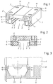
- a support body 1 for a linear roller bearing consists of a one-piece U-shaped body which has a central recess 2 for enclosing a guide rail.
- Vertical threaded holes 3, which extend on both sides of an exemption 4 from the top of the support body 1, allow the attachment of a connecting structure, for example a machine component, which is to carry out the linear reciprocating movement along the guide rail.
- the supporting body 1 is supported on the guide rail by means of rolling element circulations. It has 2 straight raceways 5 for the load-bearing rolling elements within the recess.
- the support body 1 contains a parallel return channel 6 for each track 5.
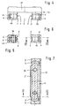
- the track 5 and the return channel 6 are each connected to one another by deflection channels 7 (FIG. 7).
- Each deflection channel 7 is arranged in a deflection body 9 resting on an end face 8 of the support body 1.
- a plurality of fastening projections 10 projecting from the end faces 8 of the support body 1 are formed in one piece with the support body 1. These have perpendicular undercuts 11, so that there are two retaining lugs on the fastening projection 10 12 result.
- the deflecting body 9 has recesses 17 which correspond to the shape and position of the fastening projections 10, it can therefore be clipped onto the fastening projections 10 in a simple manner, as a result of which the rolling element circulations of the supporting body 1 are produced.
- the support body 13 according to Figure 4 of the drawing is basically constructed the same way, but is not made in one piece.
- rolling element circulation shoes 15 are screwed on both sides, that is to say releasably fastened.
- the rolling element circulation shoes 15 have vertical threaded bores 16.
Landscapes
- Engineering & Computer Science (AREA)
- General Engineering & Computer Science (AREA)
- Mechanical Engineering (AREA)
- Bearings For Parts Moving Linearly (AREA)
Applications Claiming Priority (2)
| Application Number | Priority Date | Filing Date | Title |
|---|---|---|---|
| DE4412131 | 1994-04-08 | ||
| DE4412131A DE4412131A1 (de) | 1994-04-08 | 1994-04-08 | Wälzlager |
Publications (3)
| Publication Number | Publication Date |
|---|---|
| EP0676553A2 true EP0676553A2 (fr) | 1995-10-11 |
| EP0676553A3 EP0676553A3 (fr) | 1996-04-10 |
| EP0676553B1 EP0676553B1 (fr) | 2000-05-31 |
Family
ID=6514918
Family Applications (1)
| Application Number | Title | Priority Date | Filing Date |
|---|---|---|---|
| EP95102046A Expired - Lifetime EP0676553B1 (fr) | 1994-04-08 | 1995-02-15 | Palier linéaire à roulement |
Country Status (3)
| Country | Link |
|---|---|
| EP (1) | EP0676553B1 (fr) |
| JP (1) | JPH0842568A (fr) |
| DE (2) | DE4412131A1 (fr) |
Cited By (2)
| Publication number | Priority date | Publication date | Assignee | Title |
|---|---|---|---|---|
| EP0769627A1 (fr) * | 1995-10-17 | 1997-04-23 | Deutsche Star GmbH | Dispositif de guidage linéaire |
| EP1245845A1 (fr) * | 2001-03-29 | 2002-10-02 | Nippon Thompson Co., Ltd. | Unité de guidage linéaire |
Families Citing this family (3)
| Publication number | Priority date | Publication date | Assignee | Title |
|---|---|---|---|---|
| JP5965369B2 (ja) * | 2013-09-05 | 2016-08-03 | Thk株式会社 | 運動案内装置 |
| DE102017105733A1 (de) | 2017-03-17 | 2018-07-12 | Schaeffler Technologies AG & Co. KG | Spindelmutter für einen Kugelgewindetrieb und Verfahren zur Herstellung einer Spindelmutter |
| DE102024205871A1 (de) * | 2024-06-25 | 2026-01-08 | Robert Bosch Gesellschaft mit beschränkter Haftung | Führungswagen mit aus Metallpulver gesinterter Umlenkbaugruppe |
Family Cites Families (13)
| Publication number | Priority date | Publication date | Assignee | Title |
|---|---|---|---|---|
| GB1319680A (en) * | 1970-11-11 | 1973-06-06 | Rubber Plastics Ltd | Ball bearings |
| US4420193A (en) * | 1981-08-11 | 1983-12-13 | Hiroshi Teramachi | Linear ball bearing unit |
| JPS6040818A (ja) * | 1983-08-12 | 1985-03-04 | Hiroshi Teramachi | 直線摺動用ベアリング |
| JPS60263724A (ja) * | 1984-06-12 | 1985-12-27 | Nippon Seiko Kk | リニヤガイド装置 |
| JPS61116120A (ja) * | 1984-11-13 | 1986-06-03 | Hiroshi Teramachi | 直線運動ロ−ラ−ベアリング |
| DE3527367A1 (de) * | 1985-07-31 | 1987-02-12 | Mtu Muenchen Gmbh | Auf pulvermetallurgischem wege hergestellte bauteile |
| DE3805392A1 (de) * | 1988-02-20 | 1989-08-31 | Ipiranga Sa | Linearlager mit umlaufenden kugeln |
| DE3931351A1 (de) * | 1989-09-20 | 1991-03-28 | Werner Dipl Ing Jacob | Kugelumlaufeinheit fuer eine linearfuehrung |
| JPH0692603B2 (ja) * | 1989-10-17 | 1994-11-16 | 住友金属鉱山株式会社 | 金属焼結体製造用金属粉末及びこれを用いた金属焼結体製品の製造方法 |
| JPH03213714A (ja) * | 1990-01-17 | 1991-09-19 | Nippon Thompson Co Ltd | 樹脂製直動案内ユニット |
| DE4005582C2 (de) * | 1990-02-22 | 1996-01-25 | Neff Antriebstech Automation | Linearlager und Herstellungsverfahren für dessen Kugelumleitungseinrichtungen |
| DE4134694A1 (de) * | 1991-10-21 | 1993-04-22 | Bayer Ag | Thermoplastische formmassen, verfahren zu deren herstellung und verfahren zur herstellung von formteilen aus keramik oder metall durch sintern |
| JPH0718448B2 (ja) * | 1991-09-19 | 1995-03-06 | テイエチケー株式会社 | リニアベアリング用スライダ及びその製造法 |
-
1994
- 1994-04-08 DE DE4412131A patent/DE4412131A1/de not_active Withdrawn
-
1995
- 1995-02-15 DE DE59508407T patent/DE59508407D1/de not_active Expired - Fee Related
- 1995-02-15 EP EP95102046A patent/EP0676553B1/fr not_active Expired - Lifetime
- 1995-04-06 JP JP7081364A patent/JPH0842568A/ja active Pending
Cited By (4)
| Publication number | Priority date | Publication date | Assignee | Title |
|---|---|---|---|---|
| EP0769627A1 (fr) * | 1995-10-17 | 1997-04-23 | Deutsche Star GmbH | Dispositif de guidage linéaire |
| US6200031B1 (en) | 1995-10-17 | 2001-03-13 | Deutsche Star Gmbh | Linear guide arrangement |
| EP1245845A1 (fr) * | 2001-03-29 | 2002-10-02 | Nippon Thompson Co., Ltd. | Unité de guidage linéaire |
| US6520681B2 (en) | 2001-03-29 | 2003-02-18 | Nippon Thompson Co., Ltd. | Linear motion guide unit |
Also Published As
| Publication number | Publication date |
|---|---|
| DE4412131A1 (de) | 1995-10-12 |
| JPH0842568A (ja) | 1996-02-13 |
| EP0676553B1 (fr) | 2000-05-31 |
| EP0676553A3 (fr) | 1996-04-10 |
| DE59508407D1 (de) | 2000-07-06 |
Similar Documents
| Publication | Publication Date | Title |
|---|---|---|
| DE2945594C2 (de) | Linearlager mit vier Kugelumläufen | |
| DE69220918T2 (de) | Linearlager und sein herstellungsverfahren | |
| DE69505961T2 (de) | Lager für linearbewegung | |
| DE3309478C2 (fr) | ||
| DE69804578T2 (de) | Bewegliche Einheit mit Wälzkörper | |
| DE112007001185B4 (de) | Einstellbarer Linearschlitten und Verfahren zum Aufbau | |
| EP0391072A1 (fr) | Unité de guidage rectiligne à contact de roulement | |
| EP0143883A2 (fr) | Disposition de palier pour galets, de préférence pour supporter les galets d'un convoyeur à bande | |
| DE112006001723T5 (de) | Rollführungsvorrichtung und Verfahren zum Herstellen derselben | |
| EP2213894A1 (fr) | Cage de palier de roulement | |
| DE2341046A1 (de) | Linearbewegungskugellager oder linearkugelfuehrung | |
| DE102011003211A1 (de) | Wälzlager | |
| EP0676553B1 (fr) | Palier linéaire à roulement | |
| DE69824914T2 (de) | Apparat mit Endlos-Gleitführung | |
| DE3015430A1 (de) | Lineare kugellagereinheit und verfahren zum herstellen derselben | |
| DE19538665A1 (de) | Linearführungseinrichtung | |
| DE3442720A1 (de) | Waelzlager fuer geradlinige bewegung | |
| DE10101054B4 (de) | Halteteil | |
| DE4439804A1 (de) | Spieleinstellbares Linearlager | |
| DE3224282A1 (de) | Linearkugellagereinheit | |
| EP1954954B1 (fr) | Palier a roulement lineaire | |
| DE1425013B2 (de) | Bauelement fuer kugelfuehrungen | |
| EP1213499B1 (fr) | Palier à roulement linéaire | |
| DE102016214645A1 (de) | Lagerschale für ein Halbschalenlager, sowie Halbschalenlager und dessen Verwendung | |
| DE3102219C2 (fr) |
Legal Events
| Date | Code | Title | Description |
|---|---|---|---|
| PUAI | Public reference made under article 153(3) epc to a published international application that has entered the european phase |
Free format text: ORIGINAL CODE: 0009012 |
|
| 17P | Request for examination filed |
Effective date: 19950215 |
|
| AK | Designated contracting states |
Kind code of ref document: A2 Designated state(s): DE FR IT NL |
|
| PUAL | Search report despatched |
Free format text: ORIGINAL CODE: 0009013 |
|
| AK | Designated contracting states |
Kind code of ref document: A3 Designated state(s): DE FR IT NL |
|
| RAP1 | Party data changed (applicant data changed or rights of an application transferred) |
Owner name: INA WAELZLAGER SCHAEFFLER OHG |
|
| 17Q | First examination report despatched |
Effective date: 19980922 |
|
| RTI1 | Title (correction) |
Free format text: LINEAR ROLLING BEARING |
|
| GRAG | Despatch of communication of intention to grant |
Free format text: ORIGINAL CODE: EPIDOS AGRA |
|
| GRAG | Despatch of communication of intention to grant |
Free format text: ORIGINAL CODE: EPIDOS AGRA |
|
| GRAH | Despatch of communication of intention to grant a patent |
Free format text: ORIGINAL CODE: EPIDOS IGRA |
|
| RTI1 | Title (correction) |
Free format text: LINEAR ROLLING BEARING |
|
| GRAH | Despatch of communication of intention to grant a patent |
Free format text: ORIGINAL CODE: EPIDOS IGRA |
|
| GRAA | (expected) grant |
Free format text: ORIGINAL CODE: 0009210 |
|
| AK | Designated contracting states |
Kind code of ref document: B1 Designated state(s): DE FR IT NL |
|
| ITF | It: translation for a ep patent filed | ||
| REF | Corresponds to: |
Ref document number: 59508407 Country of ref document: DE Date of ref document: 20000706 |
|
| ET | Fr: translation filed | ||
| PLBE | No opposition filed within time limit |
Free format text: ORIGINAL CODE: 0009261 |
|
| STAA | Information on the status of an ep patent application or granted ep patent |
Free format text: STATUS: NO OPPOSITION FILED WITHIN TIME LIMIT |
|
| 26N | No opposition filed | ||
| PGFP | Annual fee paid to national office [announced via postgrant information from national office to epo] |
Ref country code: NL Payment date: 20050203 Year of fee payment: 11 |
|
| PGFP | Annual fee paid to national office [announced via postgrant information from national office to epo] |
Ref country code: FR Payment date: 20050208 Year of fee payment: 11 |
|
| PGFP | Annual fee paid to national office [announced via postgrant information from national office to epo] |
Ref country code: DE Payment date: 20050210 Year of fee payment: 11 |
|
| PGFP | Annual fee paid to national office [announced via postgrant information from national office to epo] |
Ref country code: IT Payment date: 20060228 Year of fee payment: 12 |
|
| PG25 | Lapsed in a contracting state [announced via postgrant information from national office to epo] |
Ref country code: NL Free format text: LAPSE BECAUSE OF NON-PAYMENT OF DUE FEES Effective date: 20060901 Ref country code: DE Free format text: LAPSE BECAUSE OF NON-PAYMENT OF DUE FEES Effective date: 20060901 |
|
| NLV4 | Nl: lapsed or anulled due to non-payment of the annual fee |
Effective date: 20060901 |
|
| REG | Reference to a national code |
Ref country code: FR Ref legal event code: ST Effective date: 20061031 |
|
| PG25 | Lapsed in a contracting state [announced via postgrant information from national office to epo] |
Ref country code: FR Free format text: LAPSE BECAUSE OF NON-PAYMENT OF DUE FEES Effective date: 20060228 |
|
| PG25 | Lapsed in a contracting state [announced via postgrant information from national office to epo] |
Ref country code: IT Free format text: LAPSE BECAUSE OF NON-PAYMENT OF DUE FEES Effective date: 20070215 |