EP0676569A1 - Kolbenring für einen Motor mit geringem Schadstoffausstoss - Google Patents
Kolbenring für einen Motor mit geringem Schadstoffausstoss Download PDFInfo
- Publication number
- EP0676569A1 EP0676569A1 EP95301530A EP95301530A EP0676569A1 EP 0676569 A1 EP0676569 A1 EP 0676569A1 EP 95301530 A EP95301530 A EP 95301530A EP 95301530 A EP95301530 A EP 95301530A EP 0676569 A1 EP0676569 A1 EP 0676569A1
- Authority
- EP
- European Patent Office
- Prior art keywords
- piston
- piston ring
- ring
- wall
- central body
- Prior art date
- Legal status (The legal status is an assumption and is not a legal conclusion. Google has not performed a legal analysis and makes no representation as to the accuracy of the status listed.)
- Withdrawn
Links
- 229910052751 metal Inorganic materials 0.000 claims abstract description 6
- 239000002184 metal Substances 0.000 claims abstract description 6
- 239000012530 fluid Substances 0.000 claims description 27
- 238000002485 combustion reaction Methods 0.000 abstract description 18
- 230000013011 mating Effects 0.000 abstract description 8
- 238000007789 sealing Methods 0.000 abstract description 6
- 239000003344 environmental pollutant Substances 0.000 description 12
- 231100000719 pollutant Toxicity 0.000 description 12
- 239000000463 material Substances 0.000 description 11
- 239000000567 combustion gas Substances 0.000 description 6
- 230000002093 peripheral effect Effects 0.000 description 6
- 239000007789 gas Substances 0.000 description 5
- 230000001815 facial effect Effects 0.000 description 3
- 229930195733 hydrocarbon Natural products 0.000 description 3
- 150000002430 hydrocarbons Chemical class 0.000 description 3
- 239000004215 Carbon black (E152) Substances 0.000 description 2
- 229910000831 Steel Inorganic materials 0.000 description 2
- 229910052782 aluminium Inorganic materials 0.000 description 2
- XAGFODPZIPBFFR-UHFFFAOYSA-N aluminium Chemical compound [Al] XAGFODPZIPBFFR-UHFFFAOYSA-N 0.000 description 2
- 239000010959 steel Substances 0.000 description 2
- 238000012986 modification Methods 0.000 description 1
- 230000004048 modification Effects 0.000 description 1
Images

Classifications
-
- F—MECHANICAL ENGINEERING; LIGHTING; HEATING; WEAPONS; BLASTING
- F16—ENGINEERING ELEMENTS AND UNITS; GENERAL MEASURES FOR PRODUCING AND MAINTAINING EFFECTIVE FUNCTIONING OF MACHINES OR INSTALLATIONS; THERMAL INSULATION IN GENERAL
- F16J—PISTONS; CYLINDERS; SEALINGS
- F16J9/00—Piston-rings, e.g. non-metallic piston-rings, seats therefor; Ring sealings of similar construction
- F16J9/12—Details
- F16J9/20—Rings with special cross-section; Oil-scraping rings
Definitions
- the present invention relates to a piston ring for use in an internal combustion engine, and more particularly to a piston ring for reducing emission of pollutants that has an upper surface exposed to combustion gases.
- Piston rings are well known. They are usually received within an annular groove disposed about an outer periphery of a piston. In turn, the piston is reciprocalable within a cylinder.
- a piston compresses fluids such as gases within the cylinder. In an internal combustion engine, these fluids are ignited, and expand, forcing the piston away from the point of ignition. Not all of the fluids are ignited, however. Instead, some of the fluids are typically trapped in a crevice defined between an outer radial surface of the piston and the relatively cool cylinder wall, and between the top piston ring and the top of the piston. The trapping of fluids within the crevice lowers combustion efficiency because the trapped fluids do not ignite. Further, when exhausted from the assembly, the trapped fluids increase pollutant emission levels, particularly hydrocarbon emission levels.
- piston rings To reduce the emission of pollutants it is known to position a piston ring near the top of a piston such that an upper surface of the piston ring is exposed to combustion gases.
- the piston ring includes two legs defining a channel, each leg being received in a groove of the piston.
- Such prior art piston rings include an intrinsic radial tension intended to force the piston ring into greater contact with the cylinder wall.
- piston rings with an intrinsic tension should include a controllably imbalanced or non-symmetrical cross-section with non-symmetrical grooves to encourage torsional twist.
- Intrinsic loading continuously places stresses upon the piston ring. Failure results unless piston rings of a substantial size are used.
- the continuous loading also favors damaging wear to the ring and to the cylinder wall.
- the use of torsional twist places only a small portion of the piston ring in facial contact with the combustion wall and the walls of the piston ring grooves, facilitating additional damaging wear to the ring, the walls of the piston ring grooves, and to the cylinder wall.
- the present invention relates to a piston assembly with a one-piece, symmetrical, annular top land type piston ring, having very little if any intrinsic radial tension, that is adapted to be received in mating grooves of a piston.
- an inventive piston assembly includes an annular cylinder having an inner cylinder wall defining a bore.
- An annular piston is reciprocalable along a longitudinally extending axis within the bore of the cylinder.
- the piston includes two grooves that define the angled walls of a generally keystone wedge.
- the wedge has the features of an isosceles trapezpoid, wherein the angled walls share a common length and angle and an outer wall of the wedge is parallel to the longitudinal axis.
- a single strip of metal is formed into a one-piece split annular top land type piston ring that is adapted to be received within the grooves of the piston to provide sealing engagement between the piston and the cylinder wall.
- the piston and piston ring are mated so that only a small crevice is defined between them, reducing the emission of pollutants during operation in an internal combustion engine.
- the ring has a symmetrical cross-section, a line of symmetry defined along a radial axis perpendicular to the longitudinal axis and equally spaced between a longitudinally upper surface and a longitudinally lower surface.
- the piston ring includes a central body, with an upper leg and a lower leg extending radially inwardly from the central body and defining a channel between them that is adapted to receive the wedge.
- a lower surface of the upper leg extends radially inwardly and longitudinally upwardly from the central body, and an upper surface of the lower leg extends radially inwardly and longitudinally downwardly from the central body.
- the piston ring is a so-called dead ring that has very little if any intrinsic radial tension.
- a piston ring requires only a small-cross section, typically having a longitudinal thickness between 3 and 4 mm. A smaller cross-section promotes improved heat transfer, and having less reciprocating mass, also increases assembly life and operational efficiency.
- the inventive piston ring is inexpensive to make and materials such as high strength steel or low inertia aluminum materials are preferably used.
- the inventive assembly does not have any of the leakage problems commonly associated with piston rings lacking an intrinsic radial tension. Instead the shape of the piston ring and the wedge of the piston provide a smooth sliding movement between the mating components as a dynamic force component is created in the radial direction in response to piston reciprocation along the longitudinal axis of the cylinder.
- the extent of the dynamic force component in the radial direction is related to the angle of the lower wall of the upper leg, the upper wall of the lower leg, and the mating walls of the grooves.
- the indicated surfaces and walls have a common angle relative to the radial axis, and more preferably, the common angle is between fifteen (15) and thirty (30) degrees.
- a balanced or symmetrical cross-section for both the wedge and the mating piston ring is important to the proper operation of the assembly. Torsional twist is not wanted between the piston and the piston ring since torsional twist may interfere with the urging of the central body of the piston ring toward the cylinder wall in response to the radial force component. Torsional twist is also undesirable because of the resulting reduced area of contact between the piston ring and mating components, increasing damaging wear.
- the central body includes a convex radially outer periphery.
- the radially outer periphery includes two radially outwardly extending legs adapted to contact the cylinder wall, wherein a channel is defined between them.
- the legs are shaped to provide sufficient strength against the sliding stress exerted against the legs by the cylinder wall. The use of two points of contact further reduces the tendency for the piston ring to undergo torsional twist.
- An assembly made according to the present invention is easily adapted for use in a large number of applications, including internal combustion engines and compressors.
- Figure 1 is a partial cross-section of a prior art piston and cylinder assembly.
- Figure 2 is an enlarged cross-section shown by circle 2-2 in Figure 1, illustrating a crevice between the piston and cylinder with trapped combustion gases.
- Figure 3 is a cross-sectional view showing a prior art ring with an upper surface exposed to combustion gases, the piston ring mounted on a piston and the piston positioned within a cylinder.
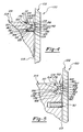
- Figure 4 is a cross-sectional view of a first embodiment of the present invention showing a piston ring with an upper surface exposed to combustion gases, the piston ring mounted on a piston and the piston positioned within a cylinder.
- Figure 5 is a cross-sectional view of a second embodiment of the present invention showing two piston rings including an upper piston ring with an upper surface exposed to combustion gases that are mounted upon a piston and the piston positioned within a cylinder.
- FIG. 1 A prior art assembly 20 is illustrated in Figure 1 that includes a cylinder 22 having an inner peripheral surface or cylinder wall 23 defining a bore.
- An annular piston 24 is reciprocalable along a longitudinally extending axis A-A within the bore of the cylinder 22.
- Piston 24 includes a plurality of annular grooves 26 about a radially outer peripheral surface 28.
- a one piece annular piston ring or sealing member 30 is mounted within each of grooves 26 to provide sealing engagement between outer peripheral surface 28 of piston 24 and cylinder wall 23.
- a portion of prior art assembly 20 is enlarged in Figure 2.
- a crevice 36 is defined between outer peripheral surface 28 of piston 24 and the relatively cool inner peripheral surface 32 of cylinder wall 34, and between the top piston ring 30 and an upper surface 31 of the piston 24.
- piston 24 compresses combustion fluids 40 such as gases within cylinder 22.
- combustion fluids 40 are ignited, and expand, forcing the piston away from the point of ignition.
- prior art assembly 20 not all of the combustion fluids 40 are ignited. Instead, some of the combustion fluids 40 are trapped within crevice 36. The trapping of fluids 40 within crevice 36 lowers combustion efficiency because the trapped fluids do not ignite.
- the trapped fluids increase pollutant emission levels, particularly hydrocarbon emission levels. The levels of pollutant emissions are related to the size of crevice 36.
- a prior art assembly 50 that includes a cylinder 52 with an annular piston 54 reciprocalable within the cylinder.
- Piston 54 includes two angled grooves 56 and 58 that define a generally keystone shaped land or wedge 60.
- a piston ring 62 includes two legs 64 and 66 that define an eccentric channel or rabbet 68. Leg 64 of ring 62 is received within groove 56 and leg 66 of ring 62 is received within groove 58.
- Piston ring 62 includes an intrinsic radial tension intended to force the piston ring 62 into greater contact with a cylinder wall 80 of cylinder 52. Intrinsic loading continuously places stress upon the piston ring and upon the cylinder. Therefore, the piston ring 62 will fail unless it is of sufficient size and material to provide the necessary strength. Yet, a smaller piston ring cross-section is desirable because such a cross-section provides improved heat transfer and less reciprocating mass. The continuous loading also favors damaging wear to the ring and to the cylinder wall.
- piston ring 62 should have an intrinsic tension
- piston ring 62 should include a controllably imbalanced or non symmetrical cross section with non-symmetrical grooves to encourage torsional twist of the piston ring. Therefore, leg 64 has a different thickness than does leg 66 of ring 62.
- legs 64 and 66 of ring 62, and grooves 56 and 58 of piston 54 are configured to promote torsional twisting. For example, the angle of slope of each of legs 64 and 66, and grooves 56 and 58, may be varied with respect to one another.
- Assembly 100 includes an annular cylinder 102 having an inner peripheral surface or cylinder wall 103 defining a bore.
- An annular piston 104 is reciprocalable along longitudinally extending axis A-A (shown in Figure 1) within the bore of cylinder 102.
- Piston 104 includes two angled grooves 106 and 108 that define a generally keystone shaped land or wedge 110.
- Upper groove 106 has a radially outer wall 112 extending generally parallel to axis A-A, and an angled lower wall 114. Wall 114 extends longitudinally downwardly and radially outwardly.
- Lower groove 108 has a radially outer wall 116 generally parallel to axis A-A, an angled upper wall 118, and a radially lower wall 119 generally perpendicular to axis A-A.
- Wall 118 extends longitudinally upwardly and radially outwardly.
- wedge 110 has the features of an isosceles trapezoid wherein the walls 114 and 118 share a common length and angle.
- a single strip of metal is formed or extruded into a one-piece split annular top land type piston ring or sealing member 120.
- Piston ring 120 is adapted to be received within grooves 106 and 108 to provide sealing engagement between piston 104 and cylinder wall 103.
- Ring 120 has a symmetrical cross-section, a line of symmetry defined along a radial axis perpendicular to the axis A-A and equally spaced between a longitudinally upper surface 122 and a longitudinally lower surface 123.
- Two legs 124 and 125 extend radially inwardly from a central body 126 to define a channel 127 receiving wedge 110.
- Upper surface 122 is adapted to be exposed to combustion fluids 40.
- upper surface 122 is preferably parallel and generally flush with an upper surface 128 of piston 104.
- upper leg 124 has a radially inner surface 130 that is adapted to be parallel to outer wall 112 of groove 106.
- Upper leg 124 also has an angled lower surface 132 that is adapted to be parallel to lower wall 114 of groove 106.
- Lower surface 132 extends radially inwardly and longitudinally upwardly of central body 126.
- lower leg 125 has a radially inner surface 134 adapted to be parallel to outer wall 116 of groove 108, and an angled upper surface 136 adapted to be parallel to upper wall 118.
- Upper surface 136 extends radially and longitudinally downwardly inwardly of central body 126.
- Lower surface 123 is adapted to be parallel to wall 119.
- surfaces 132 and 136 have the same dimensions, including a common angle with respect to the line of symmetry.
- a radially outer surface 138 of wedge 110 is adapted to correspond to a mating surface 140 of piston ring 142.
- the surfaces extend along an axis parallel to axis A-A.
- the length of surface 138 is typically less than the length of surface 140.
- the length of surface 134 is less than the length of wall 116. Therefore, some longitudinally axial movement of piston ring 120 relative to wedge 110, is permitted.
- surfaces 138 and 140 are both parallel to the reciprocalable movement of piston 104.
- Piston ring 120 also includes a barrel-shaped or convex radially outer periphery 142 that is adapted to facially contact cylinder wall 103.
- fluids 40 are trapped in a crevice 146 defined between outer wall 112 of groove 106 and outer surface 130 of leg 124, and lower wall 114 of groove 106 and upper surface 128 of piston 104.
- fewer pollutants are trapped within assembly 100.
- fluids 40 trapped within crevice 146 are more likely to ignite because the crevice does not include a relatively cool cylinder wall that inhibits combustion, further increasing efficiency and reducing the emission of pollutants such as hydrocarbons.
- Piston ring 120 of assembly 100 is a so-called dead ring that has very little if any intrinsic radial tension. This provides several advantages. First, piston ring 120 requires only a small cross-section, typically having a longitudinal thickness between 3 and 4 mm. A smaller cross section is possible because the structure of the piston is not required to support a continuous radial tension without failure. A smaller piston ring, with less material, promotes improved heat transfer from the piston ring, increasing piston ring life. Further, having less reciprocating matter increases assembly life and operational efficiency. In addition, rings with little or no intrinsic loads are less expensive to make. Nor is piston ring 120 prone to breakage as piston 104 reciprocates in cylinder 102 because of the availability of low cost, high strength steel and low inertia aluminum materials. Such materials are preferably used to make piston ring 120.
- Assembly 100 does not have any of the leakage problems commonly associated with piston rings lacking an intrinsic radial tension, wherein gas pressure buildup is required to seat the piston ring against the cylinder wall.
- the shape of the piston ring 120 and wedge 110 provides a dynamic force component in the radial direction as piston 104 reciprocates within cylinder 102.
- wall 114 of groove 106 comes into facial contact with lower surface 132 of leg 124.
- the angled relationship between wall 114 and surface 132 results in a force component being exerted in a radially outward direction and a smooth sliding movement between wall 114 and surface 132 which urges periphery 142 radially outwardly and into contact with wall 144.
- Gas buildup merely aids in the urging, but is not required.
- Wall 119 of groove 108 and lower surface 123 are configured to allow the desired movement of leg 124 relative to wedge 110.
- wall 119 and lower surface 123 come into contact when periphery 142 contacts wall 144.
- additional surface area is provided to carry load exerted longitudinally downwardly between piston 104 and piston ring 120, reducing undesirable wear to each element.
- walls 114 and 118, and surfaces 132 and 136 preferably have an angle between fifteen (15) and thirty (30) degrees relative to a radially extending axis perpendicular to axis A-A.
- the walls 114 and 118 preferably have a common angle so that wedge 110 has the general shape of an isosceles trapezoid.
- a balanced or symmetrical cross-section for both land 110 and mating piston ring 120 is very important to the proper operation of assembly 100. Torsional twist is not wanted between piston 104 and piston ring 120 since the torsional twist may interfere with the urging of periphery 142 against cylinder wall 103 in response to the radial force component. Torsional twist is also undesirable because of the resulting reduced area of contact between piston ring 120, and both cylinder 102 and piston 104, increasing damaging wear.
- FIG. 5 A second embodiment of an inventive piston cylinder assembly 150 is illustrated in Figure 5.
- Assembly 150 includes an annular cylinder 102 having an inner cylinder wall 103 defining a bore.
- An annular piston 104 is reciprocalable along a longitudinal axis A-A (shown in Figure 1).
- piston 104 includes two angled grooves 106 and 108 that define a generally keystone shaped land or wedge 110.
- a one-piece piston ring 152 is adapted to be received within grooves 106 and 108.
- Ring 152 has a symmetrical cross-section with two legs 154 and 156 extending from a central body 157 and defining a channel 158 receiving wedge 110. Piston ring 152 and 104 work in a manner similar to assembly 100.
- piston ring 152 has a different radially outer periphery 160 when compared to the convex periphery 142 of assembly 100.
- Piston ring 152 is a so-called dead weight ring with little or no intrinsic radial tension. Therefore, less piston ring material is required.
- a smaller piston ring cross-section is desirable because such a cross-section results in improved heat transfer and less reciprocating mass.
- periphery 160 includes a channel 162 defined between two legs 164 and 166, legs 164 and 166 extending radially outwardly from central body 157.
- Identically dimensioned legs 164 and 166 provide two separate points 168 and 170 of contact between piston ring 152 and cylinder wall 103. Points of contact 168 and 170 reduce the tendency for piston ring 152 to undergo torsional twist that would lessen the dynamic force component in the outward radial direction as piston 104 reciprocates along axis A-A (shown in Figure 1) within cylinder 102.
- leg 164 and 166 are shaped to have more material at an inner radial location compared with an outer radial location to provide sufficient strength against the sliding stresses exerted against legs 164 and 166 by cylinder wall 103 while minimizing material requirements. Therefore, leg 164 includes an longitudinally upwardly and radially outwardly extending angled wall 172. Leg 166 includes a longitudinally downwardly radially outwardly extending angled wall 174. An upper surface 176 and a lower surface 178 of piston ring 152 both include a chamfer 180 disposed adjacent points of contact 168 and 170, respectively, to further minimize material.
- assembly 150 includes a conventional piston ring 30. While a specialized piston ring 152 is required to improve combustion efficiency and reduce pollutant emission, such rings are only required at the top of the piston. Therefore, conventional piston rings may still be used.
Landscapes
- Engineering & Computer Science (AREA)
- General Engineering & Computer Science (AREA)
- Mechanical Engineering (AREA)
- Pistons, Piston Rings, And Cylinders (AREA)
Applications Claiming Priority (2)
| Application Number | Priority Date | Filing Date | Title |
|---|---|---|---|
| US209156 | 1994-03-10 | ||
| US08/209,156 US5450783A (en) | 1994-03-10 | 1994-03-10 | Low emission piston ring |
Publications (1)
| Publication Number | Publication Date |
|---|---|
| EP0676569A1 true EP0676569A1 (de) | 1995-10-11 |
Family
ID=22777587
Family Applications (1)
| Application Number | Title | Priority Date | Filing Date |
|---|---|---|---|
| EP95301530A Withdrawn EP0676569A1 (de) | 1994-03-10 | 1995-03-09 | Kolbenring für einen Motor mit geringem Schadstoffausstoss |
Country Status (3)
| Country | Link |
|---|---|
| US (1) | US5450783A (de) |
| EP (1) | EP0676569A1 (de) |
| JP (1) | JPH07280095A (de) |
Cited By (3)
| Publication number | Priority date | Publication date | Assignee | Title |
|---|---|---|---|---|
| WO1996016285A1 (de) * | 1994-11-17 | 1996-05-30 | Hermann Meckes | Kolbenringdichtung |
| CN104832399A (zh) * | 2014-03-18 | 2015-08-12 | 梁嘉麟 | 采用无端隙l型非金属活塞环形成全无余隙结构压缩机的方法 |
| DE102017124698A1 (de) * | 2017-10-23 | 2019-04-25 | Federal-Mogul Burscheid Gmbh | Kolben und Kolbenring mit reduziertem Blow-By |
Families Citing this family (17)
| Publication number | Priority date | Publication date | Assignee | Title |
|---|---|---|---|---|
| US5676380A (en) * | 1996-10-02 | 1997-10-14 | Ingersoll-Rand Company | Venting piston ring |
| JPH11182679A (ja) * | 1997-12-24 | 1999-07-06 | Sanshin Ind Co Ltd | 内燃エンジン |
| US6347575B1 (en) | 1999-06-30 | 2002-02-19 | Benjamin V. Booher | Low emission piston and ring for internal combustion engine |
| US7370866B2 (en) * | 2004-01-15 | 2008-05-13 | Macrotech Polyseal, Inc. | Sleeve element having a biasable end region, apparatus including same, and method of use |
| DE102006010674A1 (de) * | 2005-09-14 | 2007-03-15 | Continental Teves Ag & Co. Ohg | Kolbenpumpe |
| JP5024986B2 (ja) * | 2006-12-08 | 2012-09-12 | Hoya株式会社 | 内視鏡の操作弁 |
| US8668206B2 (en) * | 2009-06-11 | 2014-03-11 | Mueller International, Llc | Face seal gasket |
| JP2011169421A (ja) * | 2010-02-19 | 2011-09-01 | Isuzu Motors Ltd | ピストンリング |
| CN102384065B (zh) * | 2010-08-30 | 2015-07-22 | 中国计量学院 | 能降低活塞与气缸之间余隙的半v型活塞环及其加工方法 |
| CN102384062B (zh) * | 2010-08-30 | 2015-12-16 | 中国计量学院 | 活塞往复式压缩机的全无余隙机型的结构 |
| CN102220956A (zh) * | 2010-08-31 | 2011-10-19 | 梁嘉麟 | 能够降低活塞与气缸之间余隙的v型活塞环的结构形式 |
| CN102384061A (zh) * | 2010-09-02 | 2012-03-21 | 梁嘉麟 | 能够降低活塞与气缸之间余隙的活塞环结构及其加工方法 |
| CN102454576A (zh) * | 2010-10-22 | 2012-05-16 | 梁嘉麟 | 能够降低活塞与气缸之间余隙的半v型活塞环的结构形式 |
| US10113643B2 (en) * | 2014-03-18 | 2018-10-30 | Ford Global Technologies, Llc | Compression piston ring for an internal combustion engine |
| RU2581749C1 (ru) * | 2014-10-20 | 2016-04-20 | Евгений Николаевич Захаров | Уплотнительный узел поршневого двигателя внутреннего сгорания |
| AU2016228841B2 (en) | 2015-03-10 | 2020-06-18 | Liquidpiston, Inc. | High power density and efficiency epitrochoidal rotary engine |
| IL261485B2 (en) * | 2016-03-10 | 2023-04-01 | Liquidpiston Inc | Piston ring for reducing the volume of a hatch |
Citations (4)
| Publication number | Priority date | Publication date | Assignee | Title |
|---|---|---|---|---|
| US3813106A (en) * | 1970-09-04 | 1974-05-28 | Eaton Corp | Piston ring |
| DE2933702B1 (de) * | 1979-08-21 | 1980-11-27 | Goetze Ag | Kolbenring fuer insbesondere Brennkraftmaschinen |
| EP0192114A2 (de) * | 1985-02-16 | 1986-08-27 | Ae Plc | Kolben |
| DE4200489A1 (de) * | 1991-01-19 | 1992-07-23 | Hitachi Metals Ltd | Zweiteiliger oelring zur verwendung in einem verbrennungsmotor, stahldraht mit modifiziertem querschnitt zur verwendung als material fuer den oelring und verfahren zur herstellung des stahldrahts |
Family Cites Families (13)
| Publication number | Priority date | Publication date | Assignee | Title |
|---|---|---|---|---|
| US2003764A (en) * | 1933-09-29 | 1935-06-04 | Carl B Welch | Piston and ring |
| US2074581A (en) * | 1934-01-06 | 1937-03-23 | Robert G Frye | Piston for engines |
| US2012956A (en) * | 1934-03-23 | 1935-09-03 | Harry B Chaffin | Piston |
| US2228495A (en) * | 1937-08-25 | 1941-01-14 | Williams Harrison Graham | Composite piston ring |
| US2296116A (en) * | 1941-05-19 | 1942-09-15 | Stanley M Pelc | Laminated piston ring |
| US3047301A (en) * | 1960-02-12 | 1962-07-31 | Lockheed Aircraft Corp | Static sealing assembly |
| US3198531A (en) * | 1962-01-19 | 1965-08-03 | Perfect Circle Corp | Piston ring |
| JPS4313420Y1 (de) * | 1967-08-24 | 1968-06-07 | ||
| FR1549562A (de) * | 1967-11-03 | 1968-12-13 | ||
| US3704893A (en) * | 1970-09-04 | 1972-12-05 | Eaton Corp | Piston ring |
| US3742823A (en) * | 1971-09-27 | 1973-07-03 | M Fiedler | Piston structure |
| US4877257A (en) * | 1987-08-19 | 1989-10-31 | Ide Russell D | Piston ring |
| SU1539358A1 (ru) * | 1988-03-01 | 1990-01-30 | Кишиневский политехнический институт им.С.Лазо | Поршневое кольцо |
-
1994
- 1994-03-10 US US08/209,156 patent/US5450783A/en not_active Expired - Fee Related
-
1995
- 1995-03-09 EP EP95301530A patent/EP0676569A1/de not_active Withdrawn
- 1995-03-10 JP JP7078450A patent/JPH07280095A/ja active Pending
Patent Citations (4)
| Publication number | Priority date | Publication date | Assignee | Title |
|---|---|---|---|---|
| US3813106A (en) * | 1970-09-04 | 1974-05-28 | Eaton Corp | Piston ring |
| DE2933702B1 (de) * | 1979-08-21 | 1980-11-27 | Goetze Ag | Kolbenring fuer insbesondere Brennkraftmaschinen |
| EP0192114A2 (de) * | 1985-02-16 | 1986-08-27 | Ae Plc | Kolben |
| DE4200489A1 (de) * | 1991-01-19 | 1992-07-23 | Hitachi Metals Ltd | Zweiteiliger oelring zur verwendung in einem verbrennungsmotor, stahldraht mit modifiziertem querschnitt zur verwendung als material fuer den oelring und verfahren zur herstellung des stahldrahts |
Cited By (4)
| Publication number | Priority date | Publication date | Assignee | Title |
|---|---|---|---|---|
| WO1996016285A1 (de) * | 1994-11-17 | 1996-05-30 | Hermann Meckes | Kolbenringdichtung |
| CN104832399A (zh) * | 2014-03-18 | 2015-08-12 | 梁嘉麟 | 采用无端隙l型非金属活塞环形成全无余隙结构压缩机的方法 |
| DE102017124698A1 (de) * | 2017-10-23 | 2019-04-25 | Federal-Mogul Burscheid Gmbh | Kolben und Kolbenring mit reduziertem Blow-By |
| DE102017124698B4 (de) | 2017-10-23 | 2019-05-16 | Federal-Mogul Burscheid Gmbh | Kolben und Kolbenring mit reduziertem Blow-By |
Also Published As
| Publication number | Publication date |
|---|---|
| US5450783A (en) | 1995-09-19 |
| JPH07280095A (ja) | 1995-10-27 |
Similar Documents
| Publication | Publication Date | Title |
|---|---|---|
| US5450783A (en) | Low emission piston ring | |
| EP2045488A1 (de) | Kolbenring eines Kolbenmotors | |
| US6378872B1 (en) | Seal assembly | |
| GB2189853A (en) | Reciprocating engine | |
| EP1657477B1 (de) | Abstandsstückspreizer | |
| US20140013939A1 (en) | Wrist pin and method of reducing wear between members thereof, connecting rod, piston and methods of contructing same | |
| CA1093111A (en) | Low friction balanced piston ring | |
| US5072653A (en) | Piston biased to one side to cover ring gap | |
| US6450143B1 (en) | Heavy-duty valve stem seal assembly | |
| US6113107A (en) | Self-lubricated and-adjusted piston ring | |
| US3542376A (en) | Piston and ring construction | |
| US20010048199A1 (en) | Piston assembly with piston ring support and sealing member | |
| EP0800627B1 (de) | Kolbenanordnung mit kolbenringstütze und dichtungsglied | |
| US5035210A (en) | Piston assembly of internal combustion engine | |
| US7429047B1 (en) | Piston ring assembly | |
| US9334959B2 (en) | Radially notched piston rings | |
| US3901131A (en) | Anti-emissions compression piston ring | |
| KR102539762B1 (ko) | 피스톤 링의 조합체 및 피스톤과 피스톤 링의 조합 구조체 | |
| US5261362A (en) | Piston assembly having multiple piece compression ring | |
| EP0695894B1 (de) | Kompressionsring für brennkraftmotor | |
| RU2177569C2 (ru) | Составное поршневое кольцо | |
| US11313467B1 (en) | Piston ring seals | |
| US5398945A (en) | Piston ring of "Y" cross-section | |
| CN118541540A (zh) | 内燃机的气体密封结构 | |
| US20200284344A1 (en) | Piston ring with inlaid dlc coating and method of manufacturing |
Legal Events
| Date | Code | Title | Description |
|---|---|---|---|
| PUAI | Public reference made under article 153(3) epc to a published international application that has entered the european phase |
Free format text: ORIGINAL CODE: 0009012 |
|
| AK | Designated contracting states |
Kind code of ref document: A1 Designated state(s): DE FR GB |
|
| 17P | Request for examination filed |
Effective date: 19960404 |
|
| 17Q | First examination report despatched |
Effective date: 19990208 |
|
| STAA | Information on the status of an ep patent application or granted ep patent |
Free format text: STATUS: THE APPLICATION IS DEEMED TO BE WITHDRAWN |
|
| 18D | Application deemed to be withdrawn |
Effective date: 20001003 |