EP0676570A1 - Joint combine - Google Patents
Joint combine Download PDFInfo
- Publication number
- EP0676570A1 EP0676570A1 EP94916424A EP94916424A EP0676570A1 EP 0676570 A1 EP0676570 A1 EP 0676570A1 EP 94916424 A EP94916424 A EP 94916424A EP 94916424 A EP94916424 A EP 94916424A EP 0676570 A1 EP0676570 A1 EP 0676570A1
- Authority
- EP
- European Patent Office
- Prior art keywords
- sheet
- seal material
- substances
- gasket
- rubber
- Prior art date
- Legal status (The legal status is an assumption and is not a legal conclusion. Google has not performed a legal analysis and makes no representation as to the accuracy of the status listed.)
- Granted
Links
- 239000000463 material Substances 0.000 claims abstract description 169
- 239000000126 substance Substances 0.000 claims description 57
- 239000002131 composite material Substances 0.000 claims description 44
- 239000000758 substrate Substances 0.000 claims description 44
- OKTJSMMVPCPJKN-UHFFFAOYSA-N Carbon Chemical compound [C] OKTJSMMVPCPJKN-UHFFFAOYSA-N 0.000 claims description 25
- 239000010439 graphite Substances 0.000 claims description 25
- 229910002804 graphite Inorganic materials 0.000 claims description 25
- 229920001971 elastomer Polymers 0.000 claims description 22
- 229920001343 polytetrafluoroethylene Polymers 0.000 claims description 22
- 239000004810 polytetrafluoroethylene Substances 0.000 claims description 22
- 239000005060 rubber Substances 0.000 claims description 22
- 229920005989 resin Polymers 0.000 claims description 21
- 239000011347 resin Substances 0.000 claims description 21
- -1 polytetrafluoroethylene Polymers 0.000 claims description 13
- 239000000835 fiber Substances 0.000 claims description 11
- 229910052751 metal Inorganic materials 0.000 claims description 9
- 239000002184 metal Substances 0.000 claims description 9
- 239000010445 mica Substances 0.000 claims description 9
- 229910052618 mica group Inorganic materials 0.000 claims description 9
- 239000012779 reinforcing material Substances 0.000 claims description 9
- 239000004519 grease Substances 0.000 claims description 8
- 230000007797 corrosion Effects 0.000 claims description 7
- 238000005260 corrosion Methods 0.000 claims description 7
- 239000012784 inorganic fiber Substances 0.000 claims description 7
- 238000001179 sorption measurement Methods 0.000 claims description 7
- 238000009751 slip forming Methods 0.000 claims description 5
- 230000003449 preventive effect Effects 0.000 claims 5
- 239000003566 sealing material Substances 0.000 abstract 6
- 230000035515 penetration Effects 0.000 description 10
- 238000007789 sealing Methods 0.000 description 9
- 239000010410 layer Substances 0.000 description 8
- 230000000694 effects Effects 0.000 description 7
- 229920002379 silicone rubber Polymers 0.000 description 7
- 239000004945 silicone rubber Substances 0.000 description 7
- 238000009434 installation Methods 0.000 description 5
- NINIDFKCEFEMDL-UHFFFAOYSA-N Sulfur Chemical compound [S] NINIDFKCEFEMDL-UHFFFAOYSA-N 0.000 description 4
- 239000000853 adhesive Substances 0.000 description 4
- 239000000843 powder Substances 0.000 description 4
- 239000011593 sulfur Substances 0.000 description 4
- 229910052717 sulfur Inorganic materials 0.000 description 4
- 244000043261 Hevea brasiliensis Species 0.000 description 3
- 229920000459 Nitrile rubber Polymers 0.000 description 3
- ISWSIDIOOBJBQZ-UHFFFAOYSA-N Phenol Chemical compound OC1=CC=CC=C1 ISWSIDIOOBJBQZ-UHFFFAOYSA-N 0.000 description 3
- 239000000460 chlorine Substances 0.000 description 3
- 229910052801 chlorine Inorganic materials 0.000 description 3
- 239000012530 fluid Substances 0.000 description 3
- 229920001973 fluoroelastomer Polymers 0.000 description 3
- 239000011888 foil Substances 0.000 description 3
- 238000003475 lamination Methods 0.000 description 3
- 229920003052 natural elastomer Polymers 0.000 description 3
- 229920001194 natural rubber Polymers 0.000 description 3
- 229920001084 poly(chloroprene) Polymers 0.000 description 3
- 239000005995 Aluminium silicate Substances 0.000 description 2
- 229920000049 Carbon (fiber) Polymers 0.000 description 2
- XEEYBQQBJWHFJM-UHFFFAOYSA-N Iron Chemical compound [Fe] XEEYBQQBJWHFJM-UHFFFAOYSA-N 0.000 description 2
- 239000004698 Polyethylene Substances 0.000 description 2
- 239000004113 Sepiolite Substances 0.000 description 2
- 229920000800 acrylic rubber Polymers 0.000 description 2
- 229910052782 aluminium Inorganic materials 0.000 description 2
- XAGFODPZIPBFFR-UHFFFAOYSA-N aluminium Chemical compound [Al] XAGFODPZIPBFFR-UHFFFAOYSA-N 0.000 description 2
- 235000012211 aluminium silicate Nutrition 0.000 description 2
- 229920006231 aramid fiber Polymers 0.000 description 2
- 238000005452 bending Methods 0.000 description 2
- 239000004917 carbon fiber Substances 0.000 description 2
- 229910001919 chlorite Inorganic materials 0.000 description 2
- 229910052619 chlorite group Inorganic materials 0.000 description 2
- QBWCMBCROVPCKQ-UHFFFAOYSA-N chlorous acid Chemical compound OCl=O QBWCMBCROVPCKQ-UHFFFAOYSA-N 0.000 description 2
- 239000004927 clay Substances 0.000 description 2
- 229910052570 clay Inorganic materials 0.000 description 2
- NJLLQSBAHIKGKF-UHFFFAOYSA-N dipotassium dioxido(oxo)titanium Chemical compound [K+].[K+].[O-][Ti]([O-])=O NJLLQSBAHIKGKF-UHFFFAOYSA-N 0.000 description 2
- 239000000945 filler Substances 0.000 description 2
- 239000003365 glass fiber Substances 0.000 description 2
- NLYAJNPCOHFWQQ-UHFFFAOYSA-N kaolin Chemical compound O.O.O=[Al]O[Si](=O)O[Si](=O)O[Al]=O NLYAJNPCOHFWQQ-UHFFFAOYSA-N 0.000 description 2
- VNWKTOKETHGBQD-UHFFFAOYSA-N methane Chemical compound C VNWKTOKETHGBQD-UHFFFAOYSA-N 0.000 description 2
- 239000011490 mineral wool Substances 0.000 description 2
- 235000019271 petrolatum Nutrition 0.000 description 2
- 229920000058 polyacrylate Polymers 0.000 description 2
- 229920000573 polyethylene Polymers 0.000 description 2
- 230000002265 prevention Effects 0.000 description 2
- 238000000926 separation method Methods 0.000 description 2
- 229910052624 sepiolite Inorganic materials 0.000 description 2
- 235000019355 sepiolite Nutrition 0.000 description 2
- 239000010703 silicon Substances 0.000 description 2
- 229910052710 silicon Inorganic materials 0.000 description 2
- 229920002545 silicone oil Polymers 0.000 description 2
- 239000000454 talc Substances 0.000 description 2
- 229910052623 talc Inorganic materials 0.000 description 2
- 239000001993 wax Substances 0.000 description 2
- RYGMFSIKBFXOCR-UHFFFAOYSA-N Copper Chemical compound [Cu] RYGMFSIKBFXOCR-UHFFFAOYSA-N 0.000 description 1
- 239000004593 Epoxy Substances 0.000 description 1
- IOVCWXUNBOPUCH-UHFFFAOYSA-M Nitrite anion Chemical compound [O-]N=O IOVCWXUNBOPUCH-UHFFFAOYSA-M 0.000 description 1
- 239000004677 Nylon Substances 0.000 description 1
- 239000004264 Petrolatum Substances 0.000 description 1
- XUIMIQQOPSSXEZ-UHFFFAOYSA-N Silicon Chemical compound [Si] XUIMIQQOPSSXEZ-UHFFFAOYSA-N 0.000 description 1
- RTAQQCXQSZGOHL-UHFFFAOYSA-N Titanium Chemical compound [Ti] RTAQQCXQSZGOHL-UHFFFAOYSA-N 0.000 description 1
- HCHKCACWOHOZIP-UHFFFAOYSA-N Zinc Chemical compound [Zn] HCHKCACWOHOZIP-UHFFFAOYSA-N 0.000 description 1
- 150000001412 amines Chemical class 0.000 description 1
- 235000013871 bee wax Nutrition 0.000 description 1
- 229940092738 beeswax Drugs 0.000 description 1
- 239000012166 beeswax Substances 0.000 description 1
- 239000011230 binding agent Substances 0.000 description 1
- 239000000919 ceramic Substances 0.000 description 1
- 239000003795 chemical substances by application Substances 0.000 description 1
- 239000011247 coating layer Substances 0.000 description 1
- 230000006835 compression Effects 0.000 description 1
- 238000007906 compression Methods 0.000 description 1
- 229910052802 copper Inorganic materials 0.000 description 1
- 239000010949 copper Substances 0.000 description 1
- 238000005536 corrosion prevention Methods 0.000 description 1
- 230000007547 defect Effects 0.000 description 1
- 230000002708 enhancing effect Effects 0.000 description 1
- 239000003822 epoxy resin Substances 0.000 description 1
- 230000001747 exhibiting effect Effects 0.000 description 1
- 230000001771 impaired effect Effects 0.000 description 1
- 229910052500 inorganic mineral Inorganic materials 0.000 description 1
- 229910052742 iron Inorganic materials 0.000 description 1
- 239000012182 japan wax Substances 0.000 description 1
- 239000011707 mineral Substances 0.000 description 1
- 239000002480 mineral oil Substances 0.000 description 1
- 235000010446 mineral oil Nutrition 0.000 description 1
- 229920001778 nylon Polymers 0.000 description 1
- 239000003921 oil Substances 0.000 description 1
- 239000012188 paraffin wax Substances 0.000 description 1
- 235000019809 paraffin wax Nutrition 0.000 description 1
- 229940066842 petrolatum Drugs 0.000 description 1
- 239000002985 plastic film Substances 0.000 description 1
- 229920006255 plastic film Polymers 0.000 description 1
- 229920000647 polyepoxide Polymers 0.000 description 1
- 230000003014 reinforcing effect Effects 0.000 description 1
- 229910001220 stainless steel Inorganic materials 0.000 description 1
- 239000010935 stainless steel Substances 0.000 description 1
- 229920003051 synthetic elastomer Polymers 0.000 description 1
- 239000005061 synthetic rubber Substances 0.000 description 1
- 229920001169 thermoplastic Polymers 0.000 description 1
- 229920001187 thermosetting polymer Polymers 0.000 description 1
- 239000004416 thermosoftening plastic Substances 0.000 description 1
- 239000010936 titanium Substances 0.000 description 1
- 229910052719 titanium Inorganic materials 0.000 description 1
- 239000010456 wollastonite Substances 0.000 description 1
- 229910052882 wollastonite Inorganic materials 0.000 description 1
- 229910052725 zinc Inorganic materials 0.000 description 1
- 239000011701 zinc Substances 0.000 description 1
Images






Classifications
-
- F—MECHANICAL ENGINEERING; LIGHTING; HEATING; WEAPONS; BLASTING
- F16—ENGINEERING ELEMENTS AND UNITS; GENERAL MEASURES FOR PRODUCING AND MAINTAINING EFFECTIVE FUNCTIONING OF MACHINES OR INSTALLATIONS; THERMAL INSULATION IN GENERAL
- F16J—PISTONS; CYLINDERS; SEALINGS
- F16J15/00—Sealings
- F16J15/02—Sealings between relatively-stationary surfaces
- F16J15/06—Sealings between relatively-stationary surfaces with solid packing compressed between sealing surfaces
- F16J15/10—Sealings between relatively-stationary surfaces with solid packing compressed between sealing surfaces with non-metallic packing
-
- F—MECHANICAL ENGINEERING; LIGHTING; HEATING; WEAPONS; BLASTING
- F16—ENGINEERING ELEMENTS AND UNITS; GENERAL MEASURES FOR PRODUCING AND MAINTAINING EFFECTIVE FUNCTIONING OF MACHINES OR INSTALLATIONS; THERMAL INSULATION IN GENERAL
- F16J—PISTONS; CYLINDERS; SEALINGS
- F16J15/00—Sealings
- F16J15/02—Sealings between relatively-stationary surfaces
- F16J15/06—Sealings between relatively-stationary surfaces with solid packing compressed between sealing surfaces
- F16J15/10—Sealings between relatively-stationary surfaces with solid packing compressed between sealing surfaces with non-metallic packing
- F16J15/12—Sealings between relatively-stationary surfaces with solid packing compressed between sealing surfaces with non-metallic packing with metal reinforcement or covering
- F16J15/121—Sealings between relatively-stationary surfaces with solid packing compressed between sealing surfaces with non-metallic packing with metal reinforcement or covering with metal reinforcement
- F16J15/122—Sealings between relatively-stationary surfaces with solid packing compressed between sealing surfaces with non-metallic packing with metal reinforcement or covering with metal reinforcement generally parallel to the surfaces
-
- F—MECHANICAL ENGINEERING; LIGHTING; HEATING; WEAPONS; BLASTING
- F16—ENGINEERING ELEMENTS AND UNITS; GENERAL MEASURES FOR PRODUCING AND MAINTAINING EFFECTIVE FUNCTIONING OF MACHINES OR INSTALLATIONS; THERMAL INSULATION IN GENERAL
- F16J—PISTONS; CYLINDERS; SEALINGS
- F16J15/00—Sealings
- F16J15/02—Sealings between relatively-stationary surfaces
- F16J15/06—Sealings between relatively-stationary surfaces with solid packing compressed between sealing surfaces
- F16J15/10—Sealings between relatively-stationary surfaces with solid packing compressed between sealing surfaces with non-metallic packing
- F16J15/104—Sealings between relatively-stationary surfaces with solid packing compressed between sealing surfaces with non-metallic packing characterised by structure
-
- Y—GENERAL TAGGING OF NEW TECHNOLOGICAL DEVELOPMENTS; GENERAL TAGGING OF CROSS-SECTIONAL TECHNOLOGIES SPANNING OVER SEVERAL SECTIONS OF THE IPC; TECHNICAL SUBJECTS COVERED BY FORMER USPC CROSS-REFERENCE ART COLLECTIONS [XRACs] AND DIGESTS
- Y10—TECHNICAL SUBJECTS COVERED BY FORMER USPC
- Y10S—TECHNICAL SUBJECTS COVERED BY FORMER USPC CROSS-REFERENCE ART COLLECTIONS [XRACs] AND DIGESTS
- Y10S277/00—Seal for a joint or juncture
- Y10S277/935—Seal made of a particular material
- Y10S277/936—Composite
- Y10S277/938—Carbon or graphite particle or filament
-
- Y—GENERAL TAGGING OF NEW TECHNOLOGICAL DEVELOPMENTS; GENERAL TAGGING OF CROSS-SECTIONAL TECHNOLOGIES SPANNING OVER SEVERAL SECTIONS OF THE IPC; TECHNICAL SUBJECTS COVERED BY FORMER USPC CROSS-REFERENCE ART COLLECTIONS [XRACs] AND DIGESTS
- Y10—TECHNICAL SUBJECTS COVERED BY FORMER USPC
- Y10S—TECHNICAL SUBJECTS COVERED BY FORMER USPC CROSS-REFERENCE ART COLLECTIONS [XRACs] AND DIGESTS
- Y10S277/00—Seal for a joint or juncture
- Y10S277/935—Seal made of a particular material
- Y10S277/944—Elastomer or plastic
- Y10S277/945—Containing fluorine
- Y10S277/946—PTFE
Definitions
- the present invention relates to a gasket which is useful for sealing a flange connection portion of a pipe joint, a passage connection portion of a fluid apparatus, or the like, and more particularly to a sheet-like composite gasket which is cut out in an arbitrary shape from a large sheet base material, and then used.
- gaskets practically used include many types such as a gasket configured by a single body of a sheet-like seal material composed of expanded graphite, or the like, and a gasket in which a sheet-like seal material and a reinforcing material such as metal foil are stacked to be formed into one piece in order to ensure strength.
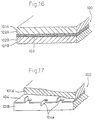
- Fig. 16 shows a gasket 100 which is composed by interposing and fixing a sheet-like reinforcing material 103 in a sandwich-like manner between two sheet-like seal materials 101A, 101B in a thickness direction through adhesive agents 102A, 102B.
- Fig. 17 shows a gasket 100 which is composed by interposing and fixing a reinforcing plate 104 wherein raised pieces 104a are partially formed, between the sheet-like seal materials 101A, 101B in the thickness direction.
- the properties of the sheet-like seal materials 101A, 101B directly affect the properties required as a gasket.
- a gasket using the sheet-like seal materials 101A, 101B composed of an expanded graphite sheet for example, there arises no problem in leakage along contact surfaces which is due to reduced surface draping properties for a flange face, etc. as shown in Figs. 18 and 19, but the existence of gaps 105 in internal layers causes penetration leakage of a sealing fluid Q to easily occur.
- a porous polytetrafluoroethylene (PTFE) sheet, a joint sheet, or a beater sheet may be used as the sheet-like seal materials 101A, 101B.
- the present invention has been conducted in view of the above-mentioned circumstances. It is an object of the invention to provide a composite gasket in which a sheet-like seal material is combined with a specific seal material in accordance with the use and the installation location, whereby leakage along contact surfaces, and penetration leakage from internal layers can be eliminated to improve the sealing properties.
- the composite gasket of the invention is a composite gasket comprising a gasket substrate including a sheet-like seal material in which a plurality of slits are formed in the sheet-like seal material, the slits elongating from the surface of the sheet-like seal material in the thickness direction, and a seal material composed of a substance which is different from the sheet-like seal material is loaded and/or stacked into the slits and/or the surface of the sheet-like seal material.
- the loading includes the filing and the stacking. Only either of the filing and the stacking may be conducted. Alternatively, both the filing and the stacking may be conducted in parallel.
- a sheet-like seal material may be used singly, or a stack in which a sheet-like seal material is disposed on the both faces or one face (i.e., at least one of the faces) of a reinforcing material may be used.
- the reinforcing material includes stainless steel (SUS); metal foil or a thin plate of copper, aluminum, titanium, iron (SPCC), or the like; such foil or plate in which many holes are formed; a plastic film; a net (mesh); and the like.
- the slits of the composite gasket having the above-mentioned configuration have a depth which is within a range of 10 to 100 % of the thickness of the sheet-like seal material in the gasket substrate, and are continuously formed in such a manner that the surface of the gasket substrate is divided in a predetermined shape.
- a sheet-like seal material in the gasket substrate useful is a sheet selected from an expanded graphite sheet, a PTFE sheet, a joint sheet, and a beater sheet.
- a PTFE sheet means both a calcined PTFE sheet which was calcined and has a density greater than 1.8 g/cm3, and a porous PTFE sheet which is not calcined and has a density of 0.2 to 1.8 g/cm3.
- inorganic fiber or organic fiber such as glass fiber, aramid fiber, carbon fiber, or rock wool; and a combination of a binder such as synthetic rubber (for example, nitrile butadiene rubber: NBR), chloroprene rubber (CR), natural rubber (NR), silicone rubber, acrylic rubber, or PTFE, and a filler which is inorganic powder such as talc, sepiolite, chlorite, wallastonite, kaolin, clay, mica, or potassium titanate.
- a binder such as synthetic rubber (for example, nitrile butadiene rubber: NBR), chloroprene rubber (CR), natural rubber (NR), silicone rubber, acrylic rubber, or PTFE
- a filler which is inorganic powder such as talc, sepiolite, chlorite, wallastonite, kaolin, clay, mica, or potassium titanate.
- the seal material to be combined useful is a substance selected from substances which are different from the substance constituting the sheet-like seal material in the gasket substrate, among substances including: impermeable substances which have no internal voids, such as rubber, resin, and grease; soft seal materials such as soft rubber, and soft resin; nonadhesive substances such as graphite, and mica; substances which are excellent in corrosion prevention, such as a sacrificial metal, and adsorption anticorrosives; creep resistant substances which are obtained by filling organic fiber, inorganic fiber, or the like in rubber or resin.
- impermeable substances which have no internal voids, such as rubber, resin, and grease
- soft seal materials such as soft rubber, and soft resin
- nonadhesive substances such as graphite, and mica
- substances which are excellent in corrosion prevention such as a sacrificial metal, and adsorption anticorrosives
- creep resistant substances which are obtained by filling organic fiber, inorganic fiber, or the like in rubber or resin.
- seal material to be combined is adequately selected from those described in detail below, in accordance with required properties which are to be improved depending on the use and the installation location of a gasket.
- a plurality of slits are formed in a surface of a sheet-like seal material in a gasket substrate, the slits elongating from the surface in the thickness direction, and a seal material composed of a substance which is different from the sheet-like seal material is loaded and/or stacked into the slits and/or the surface of the sheet-like seal material. Therefore, a large sheet base material may be produced, the sheet base material may be cut along slit lines in an arbitrary shape or size, and the cut out material may be used.
- the sheet-like seal material composed of the seal material which lacks in, for example, stretchability is provided with stretchability so that lamination separation is prevented from occurring in the case where a bending force is applied, and operability is improved.
- various problems in practical use of a gasket material including the sheet-like seal material can be solved, and various required properties which differ according to the use and the installation location of a gasket can be improved.
- a soft seal material such as described above may be selected and used as the seal material to be combined, such as that to be filled into the slits. This can improve surface draping properties which constitute one of the problems of a sheet-like seal material, so that leakage along contact surfaces is suppressed and sealing properties as a gasket are improved.
- the sheet-like seal material in the gasket substrate is configured by an expanded graphite sheet or a porous PTFE sheet which has excellent surface draping properties and is free from leakage along contact surfaces
- an impermeable material such as described above may be selected and used as the seal material to be combined. This can prevent penetration leakage from internal layers which constitutes a problem of such a sheet-like seal material, from occurring, and cooperate with surface draping properties of the expanded graphite sheet or the porous PTFE sheet so as to extremely improve the sealing properties.
- a gasket used as a seal material for a flange connection portion of a pipe joint is configured by a joint sheet or a beater sheet having problems in that flange surfaces are liable to be corroded by a foreign substance such as sulfur or chlorine ions in the sheet-like seal material in the gasket substrate, and that such a sheet easily adheres to the flange surfaces
- an anticorrosive substance or nonadhesive substance such as described above may be selected and used as the seal material to be combined. This can prevent the flange surfaces from being corroded by a foreign substance such as sulfur or chlorine ions in the seal material, whereby time-varying reduction in sealing properties can be suppressed and inconveniences due to bonding to a flange face can be prevented from arising.
- the sheet-like seal material in the gasket substrate is configured by a PTFE sheet which has a small coefficient of surface friction and which is inferior in creep resistance because of impaired heat resistance
- a creep resistant substance such as described above may be selected and used as the seal material to be combined. This increases the coefficient of friction and improves heat resistance, whereby the creeping phenomenon can be prevented from occurring.
- the seal material to be combined can firmly be integrated with the gasket substrate by the anchor effect, and the effects of improving various properties can easily be attained in a satisfactory manner.
- the seal material to be combined cannot sufficiently be integrated with the gasket substrate, and the seal material to be combined may be peeled off so that the predetermined effects of improving properties cannot be attained.
- Fig. 1 is a partial cutaway perspective view showing a composite gasket according to a first embodiment of the invention.
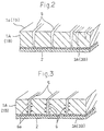
- Fig. 2 is a cutaway perspective view in the case where slits are formed in the composite gasket of the first embodiment.
- Fig. 3 is a cutaway perspective view showing in an enlarged manner a part of the composite gasket of the first embodiment.
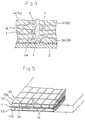
- Fig. 4 is an enlarged section view illustrating the function of the main portion of the composite gasket of the first embodiment.
- Fig. 5 is a partial cutaway perspective view showing a composite gasket according to a second embodiment of the invention.
- Fig. 6 is a cutaway perspective view showing in an enlarged manner a part of the composite gasket of the second embodiment.
- Fig. 7 is a partial cutaway perspective view showing a composite gasket according to a third embodiment of the invention.
- Fig. 8 is a partial cutaway perspective view showing a composite gasket according to a fourth embodiment of the invention.
- Fig. 9 is a partial cutaway perspective view showing a composite gasket according to a fifth embodiment of the invention which is in a state before pressurization.
- Fig. 10 is a partial cutaway perspective view showing the composite gasket according to the fifth embodiment which is in a state before pressurization.
- Fig. 11 is a table showing constituting conditions of main portions of the composite gaskets of the first to fifth embodiments.
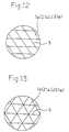
- Fig. 12 is a plan view showing another shape of the slits.
- Fig. 13 is a plan view showing a further shape of the slits.
- Fig. 14 is a plan view showing a still further shape of the slits.
- Fig. 15 is a plan view showing a still further shape of the slits.
- Fig. 16 is a partial cutaway perspective view showing a prior art gasket.
- Fig. 17 is a partial cutaway perspective view showing another prior art gasket.
- Fig. 18 is an enlarged section view of the main portion of a prior art gasket and showing a state of occurrence of penetration leakage in a prior art gasket.
- Fig. 19 is a table showing problems of seal materials in prior art gaskets.
- Fig. 1 is a partial cutaway perspective view showing a composite gasket according to a first embodiment of the invention.
- 1A and 1B designate a pair of sheet-like seal materials which are stacked in the thickness direction.
- Each of the sheet-like seal materials 1A, 1B consists of an expanded graphite sheet (see Fig. 11).
- a reinforcing material 2 is interposed in a sandwich-like manner between the seal materials 1A, 1B.
- the reinforcing material 2 is composed of, for example, SUS 304 or SUS 316L having a thickness of about 0.05 mm, and bonded to the seal materials 1A, 1B by respective thermoplastic or thermosetting adhesive agents 3A, 3B.
- the seal materials 1A, 1B, the reinforcing material 2, etc. constitute a sheet-like gasket substrate 4.
- a plurality of splits 5 are formed in the surfaces 1a, 1b of the seal materials 1A, 1B, with starting from the respective surfaces 1a, 1b and elongating in the thickness direction.
- the depth of the slits is set to be within the range of 10 to 100 % of the thickness of the seal materials 1A, 1B.
- the depth is set to an extent that the slits may reach the adhesive agent layers 3A, 3B, respectively.
- the slits 5 are continuously formed in such a manner that the surfaces 1a, 1b of the pair of the seal materials 1A, 1B are divided in a predetermined shape, for example, a lattice-like shape.
- a seal material 6 which is composed of an impermeable material such as silicone rubber that is a substance different from the seal materials 1A, 1B is filled into the slits 5 as shown in Fig. 3.
- the seal material 6 composed of the silicone rubber is filled into the slits 5, and then local filling portions 6a of the seal material 6 are formed in the inner walls of the slits 5 as shown in Fig. 3, thereby exhibiting the anchor effect. This causes the seal material 6 to be firmly integrated with the seal materials 1A, 1B.
- the filling of the seal material 6 composed of silicone rubber into the slits 5 provides stretchability to the seal materials 1A, 1B made of an expanded graphite sheet which is intrinsically inferior in stretchability, so that lamination separation which may occur in the cases such as that where a bending force is applied is suppressed. Furthermore, the gasket becomes easy to handle.
- the silicone rubber 6 in the slits 5 functions as a seal material for penetration prevention to block the gaps 7. Consequently, penetration leakage of a sealing fluid Q is prevented from occurring. This cooperates with the intrinsic small leakage along contact surfaces which is originated in the use of the expanded graphite sheet, to extremely improve sealing properties of the whole of the gasket.
- a material which can improve other properties may suitably be mixed into the seal material 6 composed of silicone rubber.
- Fig. 5 is a partial cutaway perspective view showing a sheet-like composite gasket which was obtained as a second embodiment of the invention.
- fluoro rubber is used as a seal material 16 which is filled into the slits 5, and also the surfaces of the seal materials 1A, 1B are covered in a ply manner by seal materials 17A, 17B composed of similar fluoro rubber, respectively.
- the other main portion is configured as shown in Fig. 11.
- the seal material 16 in the slits 5 is firmly integrated with the seal materials 1A, 1B by the anchor effect exerted by local filling portions 16a of the seal material, and penetration leakage from internal layers can be suppressed. Moreover, the whole area of the surfaces is covered by the seal materials 17A, 17B.
- the gasket is used as a seal material for a flange connection portion of a pipe joint, therefore, there is a less fear that the gasket bonds to the flange surfaces, and sulfur or the like is prevented from directly contacting the flange surfaces so the corrosion of the flange surfaces can effectively be prevented from occurring.
- Fig. 7 is a partial cutaway perspective view showing a sheet-like composite gasket which was obtained as a third embodiment of the invention.
- a joint sheet is used as a seal material 21, and a reinforcing material 2A composed of SUS 304 is fixed to one face of the seal material through a phenol adhesive agent 3A, thereby constituting the sheet-like gasket substrate 4.
- a seal material 26 which is obtained by mixing inorganic powder into PTFE and excellent in creep resistance is filled into the slits 5 which are formed with starting from the surface 21a of the seal material 21 and elongating in the thickness direction.
- the other main portion is configured as shown in Fig. 11.
- the use of a joint sheet as the seal material 21 enables the creep properties to be maintained, and the seal material 26 in the slits 5 can improve leakage along contact surfaces, and penetration leakage.
- Fig. 8 is a partial cutaway perspective view showing a sheet-like composite gasket which was obtained as a fourth embodiment of the invention.
- a porous PTFE sheet is used as a seal material 31, and the seal material 31 singly constitutes the gasket substrate 4.
- the slits 5 which pass through the seal material 31 in the thickness direction are formed in a lattice-like shape in the surface 31a of the seal material 31.
- a seal material 16 composed of fluoro rubber is filled into the slits 5.
- the other main portion is configured as shown in Fig. 11.
- the seal material 31 composed of the porous PTFE sheet prevents the gasket from bonding to a flange surface, and the flange surface from being corroded, and the seal material 16 effectively prevents penetration leakage from internal layers from occurring.
- Figs. 9 and 10 are partial cutaway perspective views showing a sheet-like gasket which was obtained as a fifth embodiment of the invention.
- the gasket substrate 4 is configured in the same manner as that of the first embodiment. After the seal material 6 composed of silicone rubber is filled into the slits 5 as shown in Fig. 9, the gasket substrate 4 having a thickness T is pressurized in the thickness direction so that the thickness is reduced to t as shown in Fig. 10.
- the depth of the slits 5 is not restricted to the values of the embodiments. As indicated by chain lines in Fig. 2, a value advantageous to properties to be improved may adequately be selected and set within the range of 10 to 100 % of the thickness of the seal material 1A, (1B) (21) (31).
- the slits 5 in the surface of the gasket substrate 4 have a lattice-like shape. This should be considered as an example. An arbitrary shape such as shown in Figs. 12 to 15 may be selected.
- slits are formed in the surface of a sheet-like seal material in a gasket substrate, the slits elongating from the surface in the thickness direction, and a seal material composed of a substance which is different from the seal material is loaded and/or stacked into the slits and/or the surface of the seal material. Therefore, a large sheet base material may be produced, the sheet base material may be cut in an arbitrary shape or size, and the cut out material may be used.
- the invention can attain the effects that, while the reduction in properties is suppressed to a minimum level, various problems in practical use of the gasket substrate are solved, the sealing properties are ensured, and at the same time various required properties which differ according to the use and the installation location of a gasket are improved.
Landscapes
- Engineering & Computer Science (AREA)
- General Engineering & Computer Science (AREA)
- Mechanical Engineering (AREA)
- Gasket Seals (AREA)
Applications Claiming Priority (4)
| Application Number | Priority Date | Filing Date | Title |
|---|---|---|---|
| JP21591593 | 1993-08-31 | ||
| JP5215915A JP3028171B2 (ja) | 1993-08-31 | 1993-08-31 | 複合ガスケット |
| JP215915/93 | 1993-08-31 | ||
| PCT/JP1994/000869 WO1995006831A1 (fr) | 1993-08-31 | 1994-05-30 | Joint combine |
Publications (3)
| Publication Number | Publication Date |
|---|---|
| EP0676570A1 true EP0676570A1 (fr) | 1995-10-11 |
| EP0676570A4 EP0676570A4 (fr) | 1996-01-10 |
| EP0676570B1 EP0676570B1 (fr) | 2002-12-04 |
Family
ID=16680365
Family Applications (1)
| Application Number | Title | Priority Date | Filing Date |
|---|---|---|---|
| EP94916424A Expired - Lifetime EP0676570B1 (fr) | 1993-08-31 | 1994-05-30 | Joint composite |
Country Status (7)
| Country | Link |
|---|---|
| US (1) | US5992857A (fr) |
| EP (1) | EP0676570B1 (fr) |
| JP (1) | JP3028171B2 (fr) |
| KR (1) | KR100213153B1 (fr) |
| AU (1) | AU673932B2 (fr) |
| DE (1) | DE69431830T2 (fr) |
| WO (1) | WO1995006831A1 (fr) |
Cited By (1)
| Publication number | Priority date | Publication date | Assignee | Title |
|---|---|---|---|---|
| EP0935085A2 (fr) | 1998-02-04 | 1999-08-11 | Sgl Technik Gmbh | Joint d'étanchéité stratifié avec bordure |
Families Citing this family (45)
| Publication number | Priority date | Publication date | Assignee | Title |
|---|---|---|---|---|
| CA2143678A1 (fr) * | 1992-09-10 | 1994-03-17 | Kevin P. Anderson | Compositions et methodes servant a traiter les maladies associees au virus de l'hepatite c |
| US20040049021A1 (en) * | 1992-09-10 | 2004-03-11 | Anderson Kevin P. | Compositions and mehtods for treatment of Hepatitis C virus-associated diseases |
| US6338285B2 (en) * | 1996-06-17 | 2002-01-15 | Nsk Ltd. | Feed screw device |
| KR200173843Y1 (ko) * | 1999-08-28 | 2000-03-15 | 정태정 | 고온 고압용 수면 게이지의 밀봉구조 |
| US6555223B2 (en) * | 2000-03-08 | 2003-04-29 | Sgl Technic, Inc. | Graphite structure with increased flexibility |
| JP3939909B2 (ja) * | 2000-10-04 | 2007-07-04 | 本田技研工業株式会社 | 複合シートガスケット |
| US7179525B2 (en) * | 2004-03-10 | 2007-02-20 | Gore Enterprise Holdings, Inc. | Low stress to seal expanded PTFE gasket tape |
| ATE441798T1 (de) * | 2004-03-10 | 2009-09-15 | Gore Enterprise Holdings Inc | Dichtungsband aus expandiertem ptfe zum abdichten unter niedrigen kräften |
| US8822097B2 (en) * | 2006-11-30 | 2014-09-02 | Honeywell International Inc. | Slide valve for fuel cell power generator |
| DE202008007444U1 (de) * | 2008-06-04 | 2009-10-15 | Dolmar Gmbh | Verbrennungsmotor, insbesondere für handgeführte Arbeitsgeräte |
| US8962211B2 (en) | 2008-12-15 | 2015-02-24 | Honeywell International Inc. | Rechargeable fuel cell |
| US8932780B2 (en) | 2008-12-15 | 2015-01-13 | Honeywell International Inc. | Fuel cell |
| US9276285B2 (en) | 2008-12-15 | 2016-03-01 | Honeywell International Inc. | Shaped fuel source and fuel cell |
| US20110000864A1 (en) * | 2009-07-06 | 2011-01-06 | Moore Lela K | Cookware Holder and Method |
| US20110287677A1 (en) | 2010-05-19 | 2011-11-24 | Garlock Sealing Technologies, Llc | Flexible reinforced gasket |
| US9234589B2 (en) * | 2010-10-20 | 2016-01-12 | Garlock Sealing Technologies, Llc | Extreme temperature gasket and method of making the same |
| US20130269666A1 (en) * | 2011-08-12 | 2013-10-17 | Mcalister Technologies, Llc | Combustion chamber inserts and associated methods of use and manufacture |
| US20130082447A1 (en) | 2011-10-04 | 2013-04-04 | Garlock Sealing Technologies, Llc | Spiral wound gasket |
| WO2014003807A1 (fr) | 2012-06-26 | 2014-01-03 | Garlock Sealing Technologies Llc | Matériau de joint, joints et procédés correspondants |
| JP5919134B2 (ja) * | 2012-08-09 | 2016-05-18 | 日立Geニュークリア・エナジー株式会社 | プラントの接続部構造 |
| USD738473S1 (en) | 2012-10-19 | 2015-09-08 | Garlock Sealing Technologies, Llc | Gasket having raised sealing surface pattern |
| US9963395B2 (en) | 2013-12-11 | 2018-05-08 | Baker Hughes, A Ge Company, Llc | Methods of making carbon composites |
| US9325012B1 (en) | 2014-09-17 | 2016-04-26 | Baker Hughes Incorporated | Carbon composites |
| US10315922B2 (en) | 2014-09-29 | 2019-06-11 | Baker Hughes, A Ge Company, Llc | Carbon composites and methods of manufacture |
| US10196875B2 (en) | 2014-09-30 | 2019-02-05 | Baker Hughes, A Ge Company, Llc | Deployment of expandable graphite |
| US10480288B2 (en) | 2014-10-15 | 2019-11-19 | Baker Hughes, A Ge Company, Llc | Articles containing carbon composites and methods of manufacture |
| US9962903B2 (en) | 2014-11-13 | 2018-05-08 | Baker Hughes, A Ge Company, Llc | Reinforced composites, methods of manufacture, and articles therefrom |
| US9745451B2 (en) | 2014-11-17 | 2017-08-29 | Baker Hughes Incorporated | Swellable compositions, articles formed therefrom, and methods of manufacture thereof |
| US11097511B2 (en) | 2014-11-18 | 2021-08-24 | Baker Hughes, A Ge Company, Llc | Methods of forming polymer coatings on metallic substrates |
| US9726300B2 (en) | 2014-11-25 | 2017-08-08 | Baker Hughes Incorporated | Self-lubricating flexible carbon composite seal |
| US9714709B2 (en) | 2014-11-25 | 2017-07-25 | Baker Hughes Incorporated | Functionally graded articles and methods of manufacture |
| US10300627B2 (en) | 2014-11-25 | 2019-05-28 | Baker Hughes, A Ge Company, Llc | Method of forming a flexible carbon composite self-lubricating seal |
| USD753275S1 (en) | 2015-03-11 | 2016-04-05 | Garlock Sealing Technologies, Llc | Gasket having raised sealing surface pattern |
| USD759219S1 (en) | 2015-03-11 | 2016-06-14 | Garlock Sealing Technologies, Llc | Gasket having raised sealing surface pattern |
| USD753274S1 (en) | 2015-03-11 | 2016-04-05 | Garlock Sealing Technologies, Llc | Gasket having raised sealing surface pattern |
| USD759217S1 (en) | 2015-03-11 | 2016-06-14 | Garlock Sealing Technologies, Llc | Gasket having raised sealing surface pattern |
| USD777016S1 (en) | 2015-03-11 | 2017-01-24 | Garlock Sealing Technologies, Llc | Gasket having raised sealing surface pattern |
| USD758728S1 (en) | 2015-03-11 | 2016-06-14 | Garlock Sealing Technologies, Llc | Gasket having raised sealing surface pattern |
| USD778142S1 (en) | 2015-03-11 | 2017-02-07 | Garlock Sealing Technologies, Llc | Gasket having raised sealing surface pattern |
| USD759218S1 (en) | 2015-03-11 | 2016-06-14 | Garlock Sealing Technologies, Llc | Gasket having raised sealing surface pattern |
| US9840887B2 (en) * | 2015-05-13 | 2017-12-12 | Baker Hughes Incorporated | Wear-resistant and self-lubricant bore receptacle packoff tool |
| US10125274B2 (en) | 2016-05-03 | 2018-11-13 | Baker Hughes, A Ge Company, Llc | Coatings containing carbon composite fillers and methods of manufacture |
| US10344559B2 (en) | 2016-05-26 | 2019-07-09 | Baker Hughes, A Ge Company, Llc | High temperature high pressure seal for downhole chemical injection applications |
| DE102018208967A1 (de) * | 2018-06-06 | 2019-12-12 | Sgl Carbon Se | Lagenverbund für eine Dichtung |
| DE102020214437A1 (de) * | 2020-11-17 | 2022-05-19 | Sgl Carbon Se | Dichtung |
Family Cites Families (29)
| Publication number | Priority date | Publication date | Assignee | Title |
|---|---|---|---|---|
| US494402A (en) * | 1893-03-28 | Gasket-packing | ||
| CH18875A (fr) * | 1899-03-06 | 1900-03-31 | Albert Lespagnol | Appareil pour l'élévation des liquides |
| US981524A (en) * | 1909-05-12 | 1911-01-10 | Empire Rubber Mfg Company | Rubber fabric. |
| US2127372A (en) * | 1935-03-08 | 1938-08-16 | Victor Mfg & Gasket Co | Coated all-metal gasket |
| US2269486A (en) * | 1941-07-15 | 1942-01-13 | Paul A Santoro | Self-sealing gasket |
| US2477267A (en) * | 1944-06-22 | 1949-07-26 | Bendix Aviat Corp | Electrically conductive sealing gasket and method of making same |
| US3841958A (en) * | 1971-09-02 | 1974-10-15 | R Delorme | Reinforced structural element and method of making the same |
| US3878100A (en) * | 1973-02-01 | 1975-04-15 | Marine Colloids Inc | Separation medium |
| GB1480218A (en) * | 1973-11-10 | 1977-07-20 | Dowty Seals Ltd | Gasket material |
| AU2431077A (en) * | 1976-04-30 | 1978-10-19 | Dowty Seals Ltd | Seals and gaskets |
| DE2706487A1 (de) * | 1977-02-16 | 1978-08-17 | Haefele Carl Heinz | Stopfbuchsdichtung fuer armaturen |
| DE2756351C2 (de) * | 1977-12-17 | 1980-01-31 | Kempchen & Co, Gmbh, 4200 Oberhausen | Dichtungsanordnung für Flanschdichtungen u.dgl |
| DE2840154C2 (de) * | 1978-09-15 | 1982-12-09 | Goetze Ag, 5093 Burscheid | Weichstoffdichtungsplatte, insbesondere Zylinderkopfdichtung für Verbrennungskraftmaschinen |
| US4223897A (en) * | 1978-11-06 | 1980-09-23 | Dana Corporation | Anti-stick, non-liquid absorbing gasket |
| JPS5576257A (en) * | 1978-12-05 | 1980-06-09 | Fuso Gomme Kogyo Kk | Packing |
| JPS5826381B2 (ja) * | 1979-04-28 | 1983-06-02 | 信越ポリマ−株式会社 | 電磁気シ−ルドガスケットおよびその製造方法 |
| JPS5757773A (en) * | 1980-09-26 | 1982-04-07 | Bridgestone Corp | Composite sealing material |
| GB2128270B (en) * | 1982-10-01 | 1986-01-22 | T & N Materials Res Ltd | Making gaskets from exfoliated graphite |
| US4758003A (en) * | 1984-04-05 | 1988-07-19 | Quantum Group, Inc. | Method and apparatus for changing physical and chemical properties of materials |
| DE3433376A1 (de) * | 1984-09-12 | 1986-03-20 | KSA Dichtsysteme GmbH & Co KG, 7143 Vaihingen | Dichtung |
| GB8607976D0 (en) * | 1986-04-01 | 1986-05-08 | Dowty Seals Ltd | Seal/gasket |
| DE3623620A1 (de) * | 1986-07-12 | 1988-01-21 | Boehringer Mannheim Gmbh | Spritzfertige, waessrige, alkalische injektionsloesungen von torasemid und verfahren zu ihrer herstellung |
| JPH0240350Y2 (fr) * | 1986-10-29 | 1990-10-29 | ||
| DE3804436A1 (de) * | 1988-02-12 | 1989-08-24 | Reinz Dichtungs Gmbh | Flachdichtung und verfahren zu ihrer herstellung |
| DE68921981T2 (de) * | 1988-05-25 | 1995-11-02 | Gore & Ass | Dichtung. |
| JPH086809B2 (ja) * | 1988-08-18 | 1996-01-29 | 日本ピラー工業株式会社 | ガスケット |
| DE69213366T2 (de) * | 1991-05-15 | 1997-01-16 | Nippon Reinz Co Ltd | Asbestfreie Zusammensetzung für Dichtungen |
| JPH06109137A (ja) * | 1992-09-24 | 1994-04-19 | Sanshin Kogyo Kk | ガスケット用基材 |
| JP2645800B2 (ja) * | 1993-12-14 | 1997-08-25 | 日本ピラー工業株式会社 | 膨張黒鉛製シール素材およびその製造方法ならびにガスケット用シート |
-
1993
- 1993-08-31 JP JP5215915A patent/JP3028171B2/ja not_active Expired - Fee Related
-
1994
- 1994-05-30 DE DE69431830T patent/DE69431830T2/de not_active Expired - Fee Related
- 1994-05-30 KR KR1019950701457A patent/KR100213153B1/ko not_active Expired - Fee Related
- 1994-05-30 EP EP94916424A patent/EP0676570B1/fr not_active Expired - Lifetime
- 1994-05-30 WO PCT/JP1994/000869 patent/WO1995006831A1/fr not_active Ceased
- 1994-05-30 AU AU68164/94A patent/AU673932B2/en not_active Ceased
-
1997
- 1997-03-21 US US08/822,462 patent/US5992857A/en not_active Expired - Fee Related
Cited By (2)
| Publication number | Priority date | Publication date | Assignee | Title |
|---|---|---|---|---|
| EP0935085A2 (fr) | 1998-02-04 | 1999-08-11 | Sgl Technik Gmbh | Joint d'étanchéité stratifié avec bordure |
| US6565099B1 (en) | 1998-02-04 | 2003-05-20 | Sgl Carbon Ag | Multilayered gasket with eyelit |
Also Published As
| Publication number | Publication date |
|---|---|
| US5992857A (en) | 1999-11-30 |
| EP0676570A4 (fr) | 1996-01-10 |
| AU673932B2 (en) | 1996-11-28 |
| WO1995006831A1 (fr) | 1995-03-09 |
| JP3028171B2 (ja) | 2000-04-04 |
| DE69431830D1 (de) | 2003-01-16 |
| DE69431830T2 (de) | 2003-09-18 |
| EP0676570B1 (fr) | 2002-12-04 |
| AU6816494A (en) | 1995-03-22 |
| KR950703712A (ko) | 1995-09-20 |
| JPH0771608A (ja) | 1995-03-17 |
| KR100213153B1 (ko) | 1999-08-02 |
Similar Documents
| Publication | Publication Date | Title |
|---|---|---|
| US5992857A (en) | Composite gasket | |
| US5765838A (en) | Sealing gasket made of expanded graphite, with opened thin-leaf surface structure | |
| EP0747615A1 (fr) | Joint d'étanchéité en graphite expansé, méthode de fabrication et matériau pour joints sous forme de feuille | |
| EP0464888A1 (fr) | Joint avec revêtements d'étanchéité dur et souple | |
| US4428593A (en) | Gasket assembly having improved sealing characteristics and method of making same | |
| US6689440B2 (en) | Metal tubing coated with multiple layers of polymeric materials | |
| EP0899488B1 (fr) | Joint d'étanchéité résistant à une haute pression | |
| US4103913A (en) | Fretting corrosion resistant gasket and method of making same | |
| US20180119855A1 (en) | Gasket | |
| US4402518A (en) | Laminated valve cover gasket assembly having sealing layers of different thicknesses and materials | |
| US6093467A (en) | High sealing gaskets | |
| GB2206162A (en) | Gaskets | |
| KR100227328B1 (ko) | 금속적층형 가스킷 | |
| US6268020B1 (en) | Method of fabricating high sealing gaskets | |
| JP2005172225A (ja) | 可撓性ストッパを備えたシーリングガスケット | |
| KR940000772A (ko) | 시일링 부재 | |
| US5722670A (en) | Sealing assembly and multi-layer gasket for resisting facing delamination and degradation | |
| US4852893A (en) | Elastomeric coated perforated metal core composite gasket and method of making same | |
| US5226662A (en) | Expanded graphite and metal core automotive head gasket | |
| KR100414004B1 (ko) | 금속 가스켓 | |
| SE450730B (sv) | Laminerad cylinderlockspackning och sett att framstella densamma | |
| KR0158051B1 (ko) | 팽창흑연제 씰소재와 그 제조방법 및 개스킷용시트 | |
| EP0508017A1 (fr) | Joint d'étanchéité en métal laminé avec une couche de graphite | |
| EP0886086B1 (fr) | Garniture plate | |
| JP3688013B2 (ja) | シリンダヘッドガスケット |
Legal Events
| Date | Code | Title | Description |
|---|---|---|---|
| PUAI | Public reference made under article 153(3) epc to a published international application that has entered the european phase |
Free format text: ORIGINAL CODE: 0009012 |
|
| 17P | Request for examination filed |
Effective date: 19950327 |
|
| AK | Designated contracting states |
Kind code of ref document: A1 Designated state(s): DE FR GB IT |
|
| A4 | Supplementary search report drawn up and despatched |
Effective date: 19951127 |
|
| AK | Designated contracting states |
Kind code of ref document: A4 Designated state(s): DE FR GB IT |
|
| 17Q | First examination report despatched |
Effective date: 19981125 |
|
| GRAG | Despatch of communication of intention to grant |
Free format text: ORIGINAL CODE: EPIDOS AGRA |
|
| RTI1 | Title (correction) |
Free format text: COMPOSITE GASKET |
|
| GRAG | Despatch of communication of intention to grant |
Free format text: ORIGINAL CODE: EPIDOS AGRA |
|
| GRAH | Despatch of communication of intention to grant a patent |
Free format text: ORIGINAL CODE: EPIDOS IGRA |
|
| GRAH | Despatch of communication of intention to grant a patent |
Free format text: ORIGINAL CODE: EPIDOS IGRA |
|
| GRAG | Despatch of communication of intention to grant |
Free format text: ORIGINAL CODE: EPIDOS AGRA |
|
| GRAH | Despatch of communication of intention to grant a patent |
Free format text: ORIGINAL CODE: EPIDOS IGRA |
|
| GRAH | Despatch of communication of intention to grant a patent |
Free format text: ORIGINAL CODE: EPIDOS IGRA |
|
| GRAH | Despatch of communication of intention to grant a patent |
Free format text: ORIGINAL CODE: EPIDOS IGRA |
|
| GRAA | (expected) grant |
Free format text: ORIGINAL CODE: 0009210 |
|
| AK | Designated contracting states |
Kind code of ref document: B1 Designated state(s): DE FR GB IT |
|
| REG | Reference to a national code |
Ref country code: GB Ref legal event code: FG4D |
|
| REF | Corresponds to: |
Ref document number: 69431830 Country of ref document: DE Date of ref document: 20030116 |
|
| ET | Fr: translation filed | ||
| PLBE | No opposition filed within time limit |
Free format text: ORIGINAL CODE: 0009261 |
|
| STAA | Information on the status of an ep patent application or granted ep patent |
Free format text: STATUS: NO OPPOSITION FILED WITHIN TIME LIMIT |
|
| 26N | No opposition filed |
Effective date: 20030905 |
|
| PGFP | Annual fee paid to national office [announced via postgrant information from national office to epo] |
Ref country code: GB Payment date: 20040427 Year of fee payment: 11 |
|
| PGFP | Annual fee paid to national office [announced via postgrant information from national office to epo] |
Ref country code: DE Payment date: 20040510 Year of fee payment: 11 |
|
| PGFP | Annual fee paid to national office [announced via postgrant information from national office to epo] |
Ref country code: FR Payment date: 20040512 Year of fee payment: 11 |
|
| PG25 | Lapsed in a contracting state [announced via postgrant information from national office to epo] |
Ref country code: IT Free format text: LAPSE BECAUSE OF NON-PAYMENT OF DUE FEES;WARNING: LAPSES OF ITALIAN PATENTS WITH EFFECTIVE DATE BEFORE 2007 MAY HAVE OCCURRED AT ANY TIME BEFORE 2007. THE CORRECT EFFECTIVE DATE MAY BE DIFFERENT FROM THE ONE RECORDED. Effective date: 20050530 Ref country code: GB Free format text: LAPSE BECAUSE OF NON-PAYMENT OF DUE FEES Effective date: 20050530 |
|
| PG25 | Lapsed in a contracting state [announced via postgrant information from national office to epo] |
Ref country code: DE Free format text: LAPSE BECAUSE OF NON-PAYMENT OF DUE FEES Effective date: 20051201 |
|
| GBPC | Gb: european patent ceased through non-payment of renewal fee |
Effective date: 20050530 |
|
| PG25 | Lapsed in a contracting state [announced via postgrant information from national office to epo] |
Ref country code: FR Free format text: LAPSE BECAUSE OF NON-PAYMENT OF DUE FEES Effective date: 20060131 |
|
| REG | Reference to a national code |
Ref country code: FR Ref legal event code: ST Effective date: 20060131 |