EP0935085A2 - Joint d'étanchéité stratifié avec bordure - Google Patents
Joint d'étanchéité stratifié avec bordure Download PDFInfo
- Publication number
- EP0935085A2 EP0935085A2 EP99101937A EP99101937A EP0935085A2 EP 0935085 A2 EP0935085 A2 EP 0935085A2 EP 99101937 A EP99101937 A EP 99101937A EP 99101937 A EP99101937 A EP 99101937A EP 0935085 A2 EP0935085 A2 EP 0935085A2
- Authority
- EP
- European Patent Office
- Prior art keywords
- flat gasket
- gasket according
- core
- graphite
- flat
- Prior art date
- Legal status (The legal status is an assumption and is not a legal conclusion. Google has not performed a legal analysis and makes no representation as to the accuracy of the status listed.)
- Granted
Links
- 229920000620 organic polymer Polymers 0.000 claims abstract description 7
- 239000011248 coating agent Substances 0.000 claims abstract description 6
- 238000000576 coating method Methods 0.000 claims abstract description 6
- 230000007704 transition Effects 0.000 claims abstract description 4
- 239000011888 foil Substances 0.000 claims description 169
- OKTJSMMVPCPJKN-UHFFFAOYSA-N Carbon Chemical compound [C] OKTJSMMVPCPJKN-UHFFFAOYSA-N 0.000 claims description 104
- 229910052751 metal Inorganic materials 0.000 claims description 99
- 239000002184 metal Substances 0.000 claims description 99
- 239000010439 graphite Substances 0.000 claims description 97
- 229910002804 graphite Inorganic materials 0.000 claims description 97
- 238000007789 sealing Methods 0.000 claims description 83
- 229920006254 polymer film Polymers 0.000 claims description 27
- -1 ether ketone Chemical class 0.000 claims description 26
- 239000000463 material Substances 0.000 claims description 22
- 230000001070 adhesive effect Effects 0.000 claims description 18
- 239000000853 adhesive Substances 0.000 claims description 17
- 238000000034 method Methods 0.000 claims description 17
- 229920000642 polymer Polymers 0.000 claims description 16
- 229920001343 polytetrafluoroethylene Polymers 0.000 claims description 15
- 239000004810 polytetrafluoroethylene Substances 0.000 claims description 15
- 229920001577 copolymer Polymers 0.000 claims description 12
- 229920001971 elastomer Polymers 0.000 claims description 10
- 239000000835 fiber Substances 0.000 claims description 8
- BFKJFAAPBSQJPD-UHFFFAOYSA-N tetrafluoroethene Chemical group FC(F)=C(F)F BFKJFAAPBSQJPD-UHFFFAOYSA-N 0.000 claims description 8
- 229910052799 carbon Inorganic materials 0.000 claims description 7
- 230000007797 corrosion Effects 0.000 claims description 7
- 238000005260 corrosion Methods 0.000 claims description 7
- 239000000806 elastomer Substances 0.000 claims description 5
- 239000000945 filler Substances 0.000 claims description 5
- 229920001721 polyimide Polymers 0.000 claims description 5
- 230000008569 process Effects 0.000 claims description 5
- 239000005060 rubber Substances 0.000 claims description 5
- YCKRFDGAMUMZLT-UHFFFAOYSA-N Fluorine atom Chemical compound [F] YCKRFDGAMUMZLT-UHFFFAOYSA-N 0.000 claims description 4
- 229920000459 Nitrile rubber Polymers 0.000 claims description 4
- 229910052782 aluminium Inorganic materials 0.000 claims description 4
- XAGFODPZIPBFFR-UHFFFAOYSA-N aluminium Chemical compound [Al] XAGFODPZIPBFFR-UHFFFAOYSA-N 0.000 claims description 4
- 239000004760 aramid Substances 0.000 claims description 4
- 239000011737 fluorine Substances 0.000 claims description 4
- 229910052731 fluorine Inorganic materials 0.000 claims description 4
- 239000010445 mica Substances 0.000 claims description 4
- 229910052618 mica group Inorganic materials 0.000 claims description 4
- 239000012783 reinforcing fiber Substances 0.000 claims description 4
- 239000000126 substance Substances 0.000 claims description 4
- 229920001169 thermoplastic Polymers 0.000 claims description 4
- NIXOWILDQLNWCW-UHFFFAOYSA-M Acrylate Chemical compound [O-]C(=O)C=C NIXOWILDQLNWCW-UHFFFAOYSA-M 0.000 claims description 3
- RYGMFSIKBFXOCR-UHFFFAOYSA-N Copper Chemical compound [Cu] RYGMFSIKBFXOCR-UHFFFAOYSA-N 0.000 claims description 3
- VGGSQFUCUMXWEO-UHFFFAOYSA-N Ethene Chemical compound C=C VGGSQFUCUMXWEO-UHFFFAOYSA-N 0.000 claims description 3
- 239000005977 Ethylene Substances 0.000 claims description 3
- 239000002033 PVDF binder Substances 0.000 claims description 3
- 239000004962 Polyamide-imide Substances 0.000 claims description 3
- 239000004695 Polyether sulfone Substances 0.000 claims description 3
- 239000004642 Polyimide Substances 0.000 claims description 3
- 239000004734 Polyphenylene sulfide Substances 0.000 claims description 3
- 239000000919 ceramic Substances 0.000 claims description 3
- 239000010949 copper Substances 0.000 claims description 3
- 229910052802 copper Inorganic materials 0.000 claims description 3
- RTZKZFJDLAIYFH-UHFFFAOYSA-N ether Substances CCOCC RTZKZFJDLAIYFH-UHFFFAOYSA-N 0.000 claims description 3
- 229910001092 metal group alloy Inorganic materials 0.000 claims description 3
- 230000035699 permeability Effects 0.000 claims description 3
- 229920000090 poly(aryl ether) Polymers 0.000 claims description 3
- 229920002312 polyamide-imide Polymers 0.000 claims description 3
- 229920006260 polyaryletherketone Polymers 0.000 claims description 3
- 229920006393 polyether sulfone Polymers 0.000 claims description 3
- 229920000069 polyphenylene sulfide Polymers 0.000 claims description 3
- 229920002981 polyvinylidene fluoride Polymers 0.000 claims description 3
- KUDUQBURMYMBIJ-UHFFFAOYSA-N 2-prop-2-enoyloxyethyl prop-2-enoate Chemical compound C=CC(=O)OCCOC(=O)C=C KUDUQBURMYMBIJ-UHFFFAOYSA-N 0.000 claims description 2
- 229910000838 Al alloy Inorganic materials 0.000 claims description 2
- 229920000049 Carbon (fiber) Polymers 0.000 claims description 2
- 229910000881 Cu alloy Inorganic materials 0.000 claims description 2
- 244000043261 Hevea brasiliensis Species 0.000 claims description 2
- 229920006231 aramid fiber Polymers 0.000 claims description 2
- 239000004917 carbon fiber Substances 0.000 claims description 2
- 239000004205 dimethyl polysiloxane Substances 0.000 claims description 2
- 235000013870 dimethyl polysiloxane Nutrition 0.000 claims description 2
- HQQADJVZYDDRJT-UHFFFAOYSA-N ethene;prop-1-ene Chemical group C=C.CC=C HQQADJVZYDDRJT-UHFFFAOYSA-N 0.000 claims description 2
- 239000005038 ethylene vinyl acetate Substances 0.000 claims description 2
- 229920001973 fluoroelastomer Polymers 0.000 claims description 2
- 229920005560 fluorosilicone rubber Polymers 0.000 claims description 2
- 239000012784 inorganic fiber Substances 0.000 claims description 2
- 229920003052 natural elastomer Polymers 0.000 claims description 2
- 229920001194 natural rubber Polymers 0.000 claims description 2
- 229920000435 poly(dimethylsiloxane) Polymers 0.000 claims description 2
- 229920001200 poly(ethylene-vinyl acetate) Polymers 0.000 claims description 2
- 238000005096 rolling process Methods 0.000 claims description 2
- 229920003048 styrene butadiene rubber Polymers 0.000 claims description 2
- 229920001897 terpolymer Polymers 0.000 claims description 2
- 239000004416 thermosoftening plastic Substances 0.000 claims description 2
- 125000000391 vinyl group Chemical group [H]C([*])=C([H])[H] 0.000 claims description 2
- 229920002554 vinyl polymer Polymers 0.000 claims description 2
- 239000003365 glass fiber Substances 0.000 claims 1
- 239000012815 thermoplastic material Substances 0.000 claims 1
- 239000010410 layer Substances 0.000 description 31
- 239000010935 stainless steel Substances 0.000 description 18
- 229910001220 stainless steel Inorganic materials 0.000 description 18
- 239000002131 composite material Substances 0.000 description 10
- 238000009792 diffusion process Methods 0.000 description 8
- 229920003023 plastic Polymers 0.000 description 8
- 239000004033 plastic Substances 0.000 description 8
- 239000003292 glue Substances 0.000 description 7
- 238000012856 packing Methods 0.000 description 7
- 239000012530 fluid Substances 0.000 description 6
- 239000007789 gas Substances 0.000 description 6
- 238000004519 manufacturing process Methods 0.000 description 6
- 230000000694 effects Effects 0.000 description 5
- 229920002313 fluoropolymer Polymers 0.000 description 5
- 239000004811 fluoropolymer Substances 0.000 description 5
- 238000005259 measurement Methods 0.000 description 5
- 238000011084 recovery Methods 0.000 description 5
- 239000004744 fabric Substances 0.000 description 4
- 239000000203 mixture Substances 0.000 description 4
- 238000012360 testing method Methods 0.000 description 4
- 239000002313 adhesive film Substances 0.000 description 3
- 230000006835 compression Effects 0.000 description 3
- 238000007906 compression Methods 0.000 description 3
- KPUWHANPEXNPJT-UHFFFAOYSA-N disiloxane Chemical class [SiH3]O[SiH3] KPUWHANPEXNPJT-UHFFFAOYSA-N 0.000 description 3
- 150000002191 fatty alcohols Chemical class 0.000 description 3
- 238000005304 joining Methods 0.000 description 3
- 238000003825 pressing Methods 0.000 description 3
- 239000003566 sealing material Substances 0.000 description 3
- IJGRMHOSHXDMSA-UHFFFAOYSA-N Atomic nitrogen Chemical compound N#N IJGRMHOSHXDMSA-UHFFFAOYSA-N 0.000 description 2
- VYPSYNLAJGMNEJ-UHFFFAOYSA-N Silicium dioxide Chemical compound O=[Si]=O VYPSYNLAJGMNEJ-UHFFFAOYSA-N 0.000 description 2
- 239000012790 adhesive layer Substances 0.000 description 2
- 229920003235 aromatic polyamide Polymers 0.000 description 2
- 230000004888 barrier function Effects 0.000 description 2
- 239000011324 bead Substances 0.000 description 2
- 239000003795 chemical substances by application Substances 0.000 description 2
- 238000010276 construction Methods 0.000 description 2
- 238000010586 diagram Methods 0.000 description 2
- 239000000839 emulsion Substances 0.000 description 2
- 238000005516 engineering process Methods 0.000 description 2
- 239000011521 glass Substances 0.000 description 2
- 229920001643 poly(ether ketone) Polymers 0.000 description 2
- 241000656145 Thyrsites atun Species 0.000 description 1
- 230000001464 adherent effect Effects 0.000 description 1
- 239000002318 adhesion promoter Substances 0.000 description 1
- 238000004026 adhesive bonding Methods 0.000 description 1
- 230000008901 benefit Effects 0.000 description 1
- IRLQAJPIHBZROB-UHFFFAOYSA-N buta-2,3-dienenitrile Chemical compound C=C=CC#N IRLQAJPIHBZROB-UHFFFAOYSA-N 0.000 description 1
- 238000003490 calendering Methods 0.000 description 1
- 230000000052 comparative effect Effects 0.000 description 1
- 238000010924 continuous production Methods 0.000 description 1
- 230000006378 damage Effects 0.000 description 1
- 230000001419 dependent effect Effects 0.000 description 1
- 238000011161 development Methods 0.000 description 1
- 238000005553 drilling Methods 0.000 description 1
- 230000007613 environmental effect Effects 0.000 description 1
- 239000003822 epoxy resin Substances 0.000 description 1
- 235000013312 flour Nutrition 0.000 description 1
- 230000009969 flowable effect Effects 0.000 description 1
- 210000004907 gland Anatomy 0.000 description 1
- 230000036541 health Effects 0.000 description 1
- HCDGVLDPFQMKDK-UHFFFAOYSA-N hexafluoropropylene Chemical group FC(F)=C(F)C(F)(F)F HCDGVLDPFQMKDK-UHFFFAOYSA-N 0.000 description 1
- 230000006872 improvement Effects 0.000 description 1
- 229910010272 inorganic material Inorganic materials 0.000 description 1
- 239000011147 inorganic material Substances 0.000 description 1
- 239000013067 intermediate product Substances 0.000 description 1
- 239000000314 lubricant Substances 0.000 description 1
- 230000007246 mechanism Effects 0.000 description 1
- QLTDWCHQCKHGGO-UHFFFAOYSA-N methane;sulfuric acid Chemical compound C.C.C.C.C.C.C.C.C.C.C.C.C.C.C.C.C.C.C.C.C.C.C.C.C.C.C.C.C.C.C.C.C.C.C.C.C.C.C.C.C.C.C.C.C.C.C.C.OS(O)(=O)=O.OS(O)(=O)=O.OS(O)(=O)=O.OS(O)(=O)=O.OS(O)(=O)=O.OS(O)(=O)=O.OS(O)(=O)=O QLTDWCHQCKHGGO-UHFFFAOYSA-N 0.000 description 1
- 239000002480 mineral oil Substances 0.000 description 1
- 235000010446 mineral oil Nutrition 0.000 description 1
- 229910052757 nitrogen Inorganic materials 0.000 description 1
- TWNQGVIAIRXVLR-UHFFFAOYSA-N oxo(oxoalumanyloxy)alumane Chemical compound O=[Al]O[Al]=O TWNQGVIAIRXVLR-UHFFFAOYSA-N 0.000 description 1
- 230000035515 penetration Effects 0.000 description 1
- 229920000647 polyepoxide Polymers 0.000 description 1
- 229920001296 polysiloxane Polymers 0.000 description 1
- 239000000843 powder Substances 0.000 description 1
- 238000012545 processing Methods 0.000 description 1
- 239000000047 product Substances 0.000 description 1
- 238000004080 punching Methods 0.000 description 1
- 239000002990 reinforced plastic Substances 0.000 description 1
- 239000000377 silicon dioxide Substances 0.000 description 1
- 235000012239 silicon dioxide Nutrition 0.000 description 1
- 239000002356 single layer Substances 0.000 description 1
- 239000004575 stone Substances 0.000 description 1
- 230000003746 surface roughness Effects 0.000 description 1
- 229920001187 thermosetting polymer Polymers 0.000 description 1
- 238000012546 transfer Methods 0.000 description 1
- 238000003466 welding Methods 0.000 description 1
- 239000002023 wood Substances 0.000 description 1
Images



Classifications
-
- F—MECHANICAL ENGINEERING; LIGHTING; HEATING; WEAPONS; BLASTING
- F16—ENGINEERING ELEMENTS AND UNITS; GENERAL MEASURES FOR PRODUCING AND MAINTAINING EFFECTIVE FUNCTIONING OF MACHINES OR INSTALLATIONS; THERMAL INSULATION IN GENERAL
- F16J—PISTONS; CYLINDERS; SEALINGS
- F16J15/00—Sealings
- F16J15/02—Sealings between relatively-stationary surfaces
- F16J15/06—Sealings between relatively-stationary surfaces with solid packing compressed between sealing surfaces
- F16J15/10—Sealings between relatively-stationary surfaces with solid packing compressed between sealing surfaces with non-metallic packing
- F16J15/12—Sealings between relatively-stationary surfaces with solid packing compressed between sealing surfaces with non-metallic packing with metal reinforcement or covering
- F16J15/121—Sealings between relatively-stationary surfaces with solid packing compressed between sealing surfaces with non-metallic packing with metal reinforcement or covering with metal reinforcement
- F16J15/122—Sealings between relatively-stationary surfaces with solid packing compressed between sealing surfaces with non-metallic packing with metal reinforcement or covering with metal reinforcement generally parallel to the surfaces
- F16J15/123—Details relating to the edges of the packing
-
- B—PERFORMING OPERATIONS; TRANSPORTING
- B32—LAYERED PRODUCTS
- B32B—LAYERED PRODUCTS, i.e. PRODUCTS BUILT-UP OF STRATA OF FLAT OR NON-FLAT, e.g. CELLULAR OR HONEYCOMB, FORM
- B32B27/00—Layered products comprising a layer of synthetic resin
- B32B27/06—Layered products comprising a layer of synthetic resin as the main or only constituent of a layer, which is next to another layer of the same or of a different material
- B32B27/08—Layered products comprising a layer of synthetic resin as the main or only constituent of a layer, which is next to another layer of the same or of a different material of synthetic resin
-
- F—MECHANICAL ENGINEERING; LIGHTING; HEATING; WEAPONS; BLASTING
- F16—ENGINEERING ELEMENTS AND UNITS; GENERAL MEASURES FOR PRODUCING AND MAINTAINING EFFECTIVE FUNCTIONING OF MACHINES OR INSTALLATIONS; THERMAL INSULATION IN GENERAL
- F16L—PIPES; JOINTS OR FITTINGS FOR PIPES; SUPPORTS FOR PIPES, CABLES OR PROTECTIVE TUBING; MEANS FOR THERMAL INSULATION IN GENERAL
- F16L23/00—Flanged joints
- F16L23/16—Flanged joints characterised by the sealing means
- F16L23/18—Flanged joints characterised by the sealing means the sealing means being rings
Definitions
- the invention relates to a flat gasket from 1. at least an inner or an outer flange or from at least an inside and an outside flange and 2. a sealing body, the inner flange at the transition to each of the cavities to be sealed by the seal and in which the one with at least one flange Sealing body made of a pressure-resistant core, the permanently resistant to temperatures of at least 150 ° C is and from a covering that is on the two flat Outside of the core is there.
- Flat seals are used in the technology for sealing rooms containing fluid products such as pipes, Containers, reaction rooms etc. used in places which these spaces have at least one transition to one other, materially separate from the first space Construction or functional part of the technical arrangement, to which they belong. Your function is there of pressure differences between the inside of the container and leakage of fluids in the space outside the container from such a container or container system or a undesired penetration of fluids into the container or to prevent the container system as much as possible.
- Patent 5,128,209 is a sealing material described, which consists of layers of a fluoropolymer, Graphite foils and metal foils exist, the layers are connected to each other by an adhesive.
- the the Development of this sealing material The task was to create a seal with good handling and good resilience. The criterion "Tightness" was of minor importance here.
- the Layers made of the fluoropolymer consist of porous and therefore for fluid permeable material. You lend the from the Existing graphite foils and the fluoropolymer foils Component of the composite material greater strength, Toughness, tensile strength and better manageability.
- a major disadvantage of this sealing material is that Permeability of fluoropolymer films for fluids in combination with the presence of glue as a connecting Means between layers. Wear the fluoropolymer films practically nothing about the tightness of the overall system, which is especially true for seals for high and highest Tightness requirements have a negative impact.
- the glue can especially with high pressures or voltages loaded seals can be a weak point because on the layers of the laminate can slide them what can ultimately lead to the inoperability of the seal or, especially in cooperation with higher ones Temperatures, fine cracks form in the adhesive layer can affect the sealing effect.
- the German Utility model G 92 08 943.7 discloses packing rings for Packings made of layers of graphite foils and Metal foils exist and the one as a diffusion barrier at least partially sheathing with a film made of polytetrafluoroethylene to have.
- the polytetrafluoroethylene films can also be sintered onto the graphite rings.
- the Mechanisms for sealing in gland packings cause, but are not without on flat seals further transferable.
- a stuffing box is in her Packing seat completely chambered and is tightened the packing glasses on the walls of the surrounding packing room pressed. Flow processes of the packing ring are here in contrast to flat seals, provided and can only go as far as the chamber around them allows.
- the Metal rings arranged in the pack serve primarily as Diffusion barriers between the graphite layers.
- the graphite layers have free diffusion paths in all directions. There are other conditions in flat seals. they are not completely chambered and must not be tightened when tightening the sealing surfaces that delimit upwards and downwards, e.g. Flanges no or only a very limited tendency to Have flow. For the leakage rate of such seals are the fine channels and diffusion paths that govern them Pull the seals through in the horizontal direction. In seals, some only made of plastics or metal such a diffusion path are practical not before. Seals of this type can be used on them but not the sealing requirements or insufficiently fulfilled. In seals with one pure plastic core, the plastic core flows under pressure and it lacks sufficient resilience.
- a flat gasket according to the generic term of claim 1, characterized in that is that on the core of the sealing body covering completely the flat outer sides of the core covered, from a gas-tight film from a organic polymers with a permanent temperature resistance of at least 150 ° C and that the sealing body is so encompassed by the at least one flange that the connection between the gas-tight film and the at least one flange is gas-tight.
- the polymer films covering the core of the sealing body have another advantageous property in addition to their low permeability to fluids. As a result of their good flowability under pressure, they adapt perfectly to the bumps and injuries that are present on the surfaces to which they are in contact, and thus also provide an excellent seal against them. If they are used in a sufficiently small thickness, their inherently unfavorable tendency to creep for seals and their low ability to spring back are negligible, since the resulting negative effects from the core, which will be shown later, have a good spring back capacity has more than to be compensated.
- the polymer films that delimit and completely cover the laminate on both flat sides must have a permanent temperature resistance of at least 150 ° C. They preferably have a permanent temperature resistance of at least 200 ° C.
- the films preferably consist of a material from the group consisting of polyaryl ether ether ketone, polyaryl ether ketone, polyphenylene sulfide, polyarylsulfone, polyether sulfone, polyimide, polyamide imide, fluorine-containing polymers.
- Fluorine-containing polymers from the group consisting of polytetrafluoroethylene, polytrifluorochloroethylene, tetrafluoroethylene-hexafluoropropylene copolymer, copolymers of tetrafluoroethylene with perfluoroalkyl vinyl ether, copolymers of ethylene and tetrafluoroethylene, polyvinylidene fluoride are particularly preferred, with those films consisting of perfluorinated organic polymers being preferred.
- the polymer films contained in the laminate have a thickness in the range from 0.005 to 1.0 mm, with thicknesses in the range from 0.03 to 0.2 mm being preferred.
- the core of the Sealing body made of a thermoplastic or consist of an elastomer, which by organic or inorganic fibers, preferably fibers with a length of no more than 20 mm in length. If the compressive strength the reinforced plastic body or If the elastomer is not sufficient, this can be caused by a content of a filler such as Silicon dioxide, aluminum oxide, carbon, graphite in Powder or stone, ceramic or wood flour on the required measure be brought.
- the reinforcing fibers of the core are preferably aramid, carbon, Graphite, glass, ceramic or metal fibers.
- thermoplastic Plastic is a plastic from the group Polyaryl ether ether ketone, polyaryl ether ketone, polyphenylene sulfide, Polyarylsulfone, polyethersulfone, polyimide, polyamideimide, fluorine-containing polymers and in particular a plastic from the group polytetrafluoroethylene, polytrifluorochloroethylene, Tetrafluoroethylene-hexafluoropropylene copolymer, Copolymers of tetrafluoroethylene with Perfluoroalkyl vinyl ether, copolymers of ethylene and Tetrafluoroethylene, polyvinylidene fluoride and as an elastomer preferably a substance from the group consisting of nitrile butadiene rubber, Styrene-butadiene rubber, natural rubber, Ethylene-propylene terpolymer, ethylene-vinyl acetate copolymer, Fluororubber, fluorosilicone rubber, vinyl
- the core of the sealing body consists of an inorganic and pressure-resistant material from the group, Graphite, mica.
- it consists of a graphite variant made of expanded Graphite has been made in foil or laminate form is available and is well known to any person skilled in the art contains such a graphite variant.
- graphite foils become graphite foils understood as well as graphite laminates.
- You will after known methods by pressing together or calendering of expanded, so-called worm-shaped graphite receive.
- Expanded graphite is caused by sudden Decompose graphite salts such as graphite bisulfate high temperatures. The production of worm-shaped Graphite can, for example, according to US 4,091,083 happen.
- the graphite foils used for the manufacture of sealing bodies according to the invention and located in these sealing bodies can have a bulk density in the range from 0.1 g / cm 3 to 1.8 g / cm 3 , the graphite foils located in the sealing bodies rather having bulk densities which in the middle and upper range of the given bulk density values. They preferably have a carbon content in the range from 90 to 99.95 percent by weight. Their thickness is in the range from 0.1 mm to 4 mm.
- the core of the sealing body can consist of only one layer or of several layers of graphite foils stacked on top of one another.
- the inorganic, high temperature resistant and pressure resistant fabric made of mica.
- This variant of the invention consists of the inorganic high temperature and pressure resistant fabric at least one graphite foil.
- Seals are the connections between the graphite foils with the metal foils and it's the connections of the Metal foils with the polymer foils of the covering free of Adhesives.
- the graphite and Contain metal foils which can not with the polymer foils of the covering connected metal foils as skewers be trained in which the skewers either just extend to one or both sides.
- a skewer with skewers on both sides which in are anchored to the two adjacent graphite foils.
- glue-free joining of Metal and graphite foils are the two foils on the Surfaces with which they are to be connected brought and using pressure and temperatures in the Compressed range of 150 to 300 ° C. With smaller ones This can be done in die presses, for large webs, heatable double belt presses or Roller mills used.
- connection between the metal and graphite foils wants to use the second method, which is preferred is, the method according to EP 0 616 884 B1, in which the Areas to be connected in the thinnest possible Layer with a separating agent Substance can be occupied and the connection by pressure and Exposure to temperature is produced.
- a flat gasket of this invention has one Sealing body made of a centrally arranged metal foil, two connected to the flat sides of this metal foil Layers of graphite foil and two with the ones facing outwards Flat sides of the two graphite foils connected metal foils, the flat sides facing outwards are completely connected with a polymer film.
- a another seal of this type has a sealing body a graphite foil arranged in the middle, on their is connected to both flat sides with a metal foil, their outward-facing surfaces with a polymer film are completely covered.
- the core of the sealing body is with the covering in each Case connected.
- an adhesive is used or it becomes an adhesive-free one Connected.
- glue can be commercially available adhesives that work at temperatures are stable above 150 ° C like silicone glue or acrylate glue be used. Since the adhesive layers in the Seals always represent a certain weak point, because they have fine channels that act as diffusion channels Cracks can form or because glue that is not too harden thermosetting networks as a lubricant for the interconnected layers of material under high pressure and possibly act at high temperatures adhesive-free connections preferred.
- Such an adhesive-free Connection between the core and the covering is created by Press the polymer film forming the covering with at least one layer of the core or a film that will later become part of a core, such as a metal foil or a graphite foil, under a temperature at which the polymer film softens and a pressure under which the connection can then be established.
- the core welds to the polymer film.
- This Process is also for polytetrafluoroethylene films applicable.
- One uses oneself for rational work advantageously presses in which at least one of the foils to be joined, e.g. over tempered Rolling, which can be heated and in which continuous Process of pressure required for joining can be applied.
- the metal foils of the sealing body can be used for any Sealing purposes usable and can be produced in foil form Metal.
- metal foils are preferred made of aluminum, aluminum alloys, copper and copper alloys and from a corrosion-resistant metal or a corrosion-resistant metal alloy such as Slides Stainless steel used.
- the metal foils preferably have a thickness in the range of 0.005 to 1 mm. In particular The thickness can also fall outside this range lie.
- the advantageous properties of the sealing body come in the flat gasket only to its best advantage if at least the inner flare or so executed and are attached that they completely the sealing body and enclose it gastight. Attaching the bead or beads can be done with the known facilities.
- the flare can be made of metal or a suitable plastic consist. Flares are preferably made of a corrosion-resistant Metal or a corrosion-resistant metal alloy used. Flanges are made of plastic preferably from a perfluorinated organic polymer, where here to establish gas tightness a material fit Connection between the flange and the polymer film of the covering by welding or contact gluing is advantageous.
- Flat seals according to the invention have at least one Leakage rate according to DIN 3535 of less than or equal to 0.1 ml / min on.
- FIGS. 1 to 12 The invention is illustrated below with reference to FIGS. 1 to 12 by way of example only with schematic representations explained further.
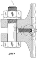
- Figure 1 shows a partial cross section through a flange connection 1 in a pipe with a flat gasket 2, 20 with inner flange 3. Between the two flanges 4, 4 'is the flat gasket 2, 20.
- the flanges 4, 4 ' By Tightening bolts 5 provided with nuts 5, which are inserted through bores 7, 7 'of the flanges 4, 4', the flanges 4, 4 'are moved towards each other and it becomes such a pressure on the flat gasket 2, 20 exercised that the flat sides 8, 8 'of the seal 2, 20th sealing against the sealing surfaces 9, 9 'of the flanges 4, 4 'are pressed.
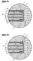
- FIGS. 2a and 2b give excerpts from the in Fig. 1 shown part of the section again, the Flat gasket 2, 20 shows in the sealing state.
- FIG. 2a shows a flat seal 20 according to the invention in front.
- Your sealing body is made from the outside in seen from a covering 10 made of a polymer film, the with a metal foil 11 is connected.
- the metal foil 11 is on the other side with a graphite foil 12 and this connected inwards again with a metal foil 11 '.
- the middle layer of the seal 20 consists of a Graphite foil 12 ', each on its two flat sides a metal foil 11 ', 11' 'is connected.
- the metal foil 11 '' is on its other flat side with a graphite foil 12 '' and this on their outward facing Flat side connected with a metal foil 11 '' '.
- the after outside facing flat side of the metal foil 11 '' ' is with a polymer film 10 'connected.
- the flat gasket 20 will on its entire inner circumference by an inner flange 3 includes. This inner flange is on the top and the Bottom of the seal 20 with the coating 10, 10 'gas-tight connected 14.
- the flat seal 20 is constructed symmetrically. The faces of the flat seal 20 of the Flanges 4, 4 'have unevenness 15, 15' into which the flowable but thin, made of a thermoplastic polymer existing covering 10, 10 'under the contact pressure of Flanges 4, 4 'has penetrated and thus all leakage paths for the medium 16 to be sealed against, reliably sealed.
- Figure 2b shows a not falling under the invention Seal assembly, which is what the core of the seal body the flat gasket 2 relates to that described in Fig. 2a Conditions. That is, the seal 2 in this Fig. 2b lacks the comparatively smooth, gas-tight Covering 10, 10 'of the seal 20 described in FIG. 2a. Their 2 sealing outer surfaces are part of metal foils 11, 11 '' '. These metal foils can be tightened the flanges 4, 4 'not in the unevenness 15, 15' of Press in flanges 4, 4 '. The result is leakage, which in particular when the internal pressures of the medium 16 are high, against which to be sealed, can become too large.
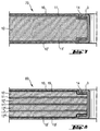
- Figure 3 shows a compartment seal 30, which consists of a Core 18 made of butadiene nitrile rubber with aramid short cut fibers is reinforced and that to reduce which contains graphite flakes as a filler, consists.
- the core is covered with polyether ketone films 10, 10 ' connected.
- the seal 30 has an inner flange 3 on the entire inner circumference of the seal 30 comprises and connected to the coverings 10, 10 'gas-tight 14 is.
- Figure 4 illustrates a flat gasket 40 in which the core 18 of the sealing body made of 1. a layer of vinylidene fluoride-hexafluoropropylene copolymer, that through embedded graphite short fibers is reinforced and additionally Contains graphite powder as filler and 2. from two metal foils 11, 11 'made of aluminum, which the location from the Vinylidene fluoride-hexafluoropropylene copolymer on both Completely cover flat sides. The two after outside facing flat sides of the aluminum foils 11, 11 ' are adhesive-free with coverings 10, 10 'made of polyether ketone films connected.
- the sealing body is on the Inside of the seal from an inner flange 3 and on the Outside of an outer flange 3 'comprises. Both flanges form a with the coverings 10, 10 'of the sealing body gastight connection 14.
- FIG 5 is a flat gasket 50 with a Sealing body gastight 14 enclosing inner flange 3, the from a copolymer of tetrafluoroethylene with perfluoroalkyl vinyl ether exists.
- the core of the Sealing body consists of two through each other Press connected laminates 12, 12 'from expanded Graphite have been produced. This core out Graphite is on its top and bottom Flat side adhesive-free with coverings 10, 10 'made of polytetrafluoroethylene films connected.
- Figure 6 shows a flat gasket 60 with an inner layer from a graphite laminate 12.
- the two flat sides of this Laminates 12 are covered with an epoxy resin adhesive 17, 17 ' Metal foils 11, 11 'connected from copper.
- the graphite laminate 12 and the two metal foils 11, 11 ' form the Core of the sealing body.
- the two free flat sides this core are by means of an adhesive or adhesive film 19, 19 'with a copolymer of polytetrafluoroethylene Perfluoroalkyl vinyl ether each with a coating 10, 10 ' a polyimide film connected.
- the inner flange 3 from Stainless steel covers the entire sealing body its inner circumference and is gas-tight 14 with the coverings 10, 10 'connected.
- Figure 7 shows a flat gasket 70 that the Flat seal 60 in Figure 6 is similar.
- the difference to the seal 60 of FIG. 6 is that in the Seal 70 the connections between the graphite laminate 12th and the metal foils 11, 11 'and between the metal foils 11, 11 'and the pads 10, 10' without using Adhesives or films acting as adhesives have been produced are.
- the connections here were made by applying high Temperatures in connection with a suitable pressure manufactured.
- FIG. 8 shows a flat seal 80 with on the coverings 10, 10 'gas-tight 14 final inner flange 3, the Sealing body made of a sequence of 4 layers of graphite foils 12, 12 ', 12' ', 12' '' and 3 layers of metal foils 11, 11 ', 11' ' made of stainless steel.
- the connection between the graphite foils 12, 12 ', 12' ', 12' '' and the metal foils 11, 11 ', 11 '' was made by pressing the components under high Temperature and high pressure.
- the two after outside facing flat sides of the sealing body are with Coverings 10, 10 'made from a film of polytetrafluoroethylene connected.
- FIG. 9 shows a flat seal (90) with an inner third and an outer flange 3 ', both made of stainless steel.
- the flanges surround the sealing body on its inside and gas-tight on its outer circumference.
- the inside of the core of the sealing body corresponds to the core of the sealing body the flat gasket (80) of Fig. 8.
- the core of the Sealing body of the flat gasket 90 in this FIG. 9 however, additionally has two metal foils 11 '' ', 11 '' '' made of stainless steel, which is adhesive-free with the adjacent graphite foils 12, 12 '' 'are connected.
- the flat seal 100 shown in FIG. 10, the Inner flange 3 engages around the sealing body and with the coverings 10, 10 'is connected gas-tight 14, has as Core of the sealing body two graphite foils 12, 12 'and three metal foils made of stainless steel 11, 11 ', 11' ', whereby these foils are arranged so that a medium metal foil 11 'with two graphite foils 12, 12' and the two Graphite foils 12, 12 'on their outward facing Flat sides again with two metal foils 11, 11 '' are connected.
- the pads 10, 10 'of Sealing body consist of two polytetrafluoroethylene foils, with the adjacent metal foils 11, 11 '' are thermally welded.
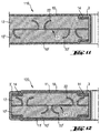
- FIG. 11 shows a flat seal 110 with a sealing body, the core of which consists of two graphite foils 12, 12 'and a skewer 21 made of stainless steel.
- the skewers 22, 22 ' engage on both sides of the skewer plate 21 in the Graphite foils 12, 12 '.
- the sealing body is on its outer flat sides from two coverings 10, 10 ' Polytetrafluoroethylene films that are compatible with their neighbors Graphite foils 12, 12 'are connected without adhesive, limited.
- the inner flange 3 made of stainless steel encompasses the Sealing body and is gas-tight with the coverings 10, 10 '14th connected.
- FIG. 12 shows a flat seal 120 with an inner third and an outer flange 3 'in the shape of a cross section represented by the left half of the seal 120.
- the core of the sealing body consists of two graphite foils 12, 12 'through one between them arranged spike 21, the skewers 22, 22 'on both sides of the skewer plate 21 in the Graphite foils 12, 12 'are anchored, are reinforced.
- the Termination of the core to the outside form two metal foils 11, 11 'made of stainless steel, with the graphite foils adjacent to them 12, 12 'are connected without adhesive.
- the flat sides of the core, which are part of the metal foils 11, 11 ', are with the two coverings 10, 10 'of polytetrafluoroethylene films thermally welded.
- Example 2 This example describes the production of a flat gasket, the sealing body of which corresponds in its construction to the sealing body of the flat gasket 90 in FIG. 9.
- two composite bodies each consisting of a polymer film and a metal film, were produced.
- the three metal foils (thickness 50 ⁇ m, material no. 1.4401), which were to be connected on both sides with graphite foils, were provided with a coating of a siloxane / fatty alcohol mixture on their two flat sides in accordance with the procedure of Example 1.
- a stack was then produced with the following layer sequence: 1.
- Graphite foil (thickness 0.51 mm, bulk density 1.0 g / cm 3 ), 3.
- Metal foil 4. Graphite foil as under 2., 5 Metal foil, 6th graphite foil as under 2., 7th metal foil, 8th graphite foil as under 2nd, 9th composite plate made of polymer foil and metal foil.
- This stack was transferred to a heated die press as described in Example 1 and pressed there to form a laminate. Sealing bodies in ring form with an inside diameter of 49 mm and an outside diameter of 92 mm were then punched out of this laminate. To produce flat seals, the sides extending along the inner diameter of the sealing body were then provided with a stainless steel flange in accordance with the procedure described in exemplary embodiment 1.
- Example 3 As example 3, flat seals were used produced according to Figure 11, the sealing body from a core reinforced with a skewer plate from two Graphite foils and a double-sided overlay from one Polymer film existed. First of all, one out of two Graphite foils and a core according to an existing skewer the method described in Example 1. The body thus obtained was then placed in a forced air oven Thoroughly dried at 105 ° C.
- the reinforced sheet metal was then placed in a polytetrafluoroethylene sheet struck as in the preceding Examples had also been used and that from the Polymer film and the tinned core body existing package in the die previously heated to 375 ° C transferred to a hot press and held there for about 5 minutes pressed under a pressure of 2 MPa. Under these Conditions welded the graphite foils to the Polymer films. From the laminate so obtained then by punching out the sealing body, inner diameter 49 mm, outer diameter 92 mm and it was made of this by attaching inner eyelets according to the Procedure according to embodiment 1 of the invention Flat seals made.
- Example 4 The core of the sealing body of the flat gasket according to exemplary embodiment 1 was used as the laminate for producing the sealing body of this flat gasket.
- two sheets of 1.05 mm thick graphite foils with a bulk density of 0.9 g / cm 3 were produced by a generally known method in a roller mill, the two rollers of which had been set to a gap width of 1.9 mm with one on both sides stainless steel skewer with material, material no. 1.4401, which had a sheet thickness of 0.1 mm, rolled with one another in such a way that a tipped sheet reinforced graphite foil body was formed, which had a graphite foil with a bulk density of 1.0 g / cm 3 on both sides.
- This laminate was used to produce ring-shaped sealing bodies, inside diameter 49 mm, outside diameter 92 mm, which were provided with a stainless steel flange along their inner circumferences by one of the usual methods.
- Table 2 shows the measured values characterizing the compression and springback behavior at room temperature and at 150 ° C.
- the measurements were carried out on the laminates from which the sealing bodies are made: Cold upsetting (KSW) and cold recovery values (KRW) at 20 ° C as well as hot upsetting (WSW) and warm recovery values (WRW) at 150 ° C; Measurement according to DIN 28090-2 20 ° C 150 ° C Laminate according to KSW (%) KRW (%) WSW (%) WRW (%) example 1 18.8 4.5 1.5 4.1
- Example 2 20.1 4.7 0.8 4.4
- Example 3 34.5 3.9 1.3 3.6 KSW and WSW, measured at a surface pressure of 20 MPa according to DIN 28091-3
- Table 3 shows the measured values for the compression and springback behavior at room temperature and at 300 ° C: Cold upsetting (KSW) and cold recovery values (KRW) at 20 ° C as well as warm upsetting (WSW) and warm recovery values (WRW) at 300 ° C; Measurement according to DIN 28090-2 20 ° C 300 ° C Laminate according to KSW (%) KRW (%) WSW (%) WRW (%) example 1 26.1 4.0 2.8 4.2 Example 2 23.8 4.3 3.7 4.5 Example 3 39.1 3.5 2.2 3.8 KSW, measured at a surface pressure of 35 MPa according to DIN 28091-4 WSW, measured at a surface pressure of 50 MPa according to DIN 28091-4
- Tables 2 and 3 show that the laminates according to Examples 1 and 2, the outer layers of There are metal foils with laminated polymer foils, do not allow to compress as much as the laminate according to Example 3, in which the metal foils in the outer two layers are missing.
- the resilience of the invention Laminates is in all temperature ranges Well.
- Diagram 1 shows the sealing effect, characterized by the specific leakage rate for a flat seal 1 with an inner flange made of stainless steel, material no. 1.4571, according to exemplary embodiment 1 or a seal corresponding to FIG. 12, but without an outer flange, as an example in comparison to a flat seal 2 with an inner flange according to the prior art, the sealing body of which was produced from a laminate which, according to exemplary embodiment 4, consisted only of two graphite foils , between which a skewer was arranged.
- the gasket used for the comparison lacked the support on both sides made of the metal foil connected to the polymer film. The test was carried out in accordance with DIN 28090. The internal pressure of the gas was 40 bar.
Landscapes
- Engineering & Computer Science (AREA)
- General Engineering & Computer Science (AREA)
- Mechanical Engineering (AREA)
- Gasket Seals (AREA)
Applications Claiming Priority (2)
| Application Number | Priority Date | Filing Date | Title |
|---|---|---|---|
| DE19804289 | 1998-02-04 | ||
| DE19804289A DE19804289A1 (de) | 1998-02-04 | 1998-02-04 | Schichtstoffdichtung mit Bördel |
Publications (3)
| Publication Number | Publication Date |
|---|---|
| EP0935085A2 true EP0935085A2 (fr) | 1999-08-11 |
| EP0935085A3 EP0935085A3 (fr) | 2000-07-05 |
| EP0935085B1 EP0935085B1 (fr) | 2004-04-07 |
Family
ID=7856570
Family Applications (1)
| Application Number | Title | Priority Date | Filing Date |
|---|---|---|---|
| EP99101937A Revoked EP0935085B1 (fr) | 1998-02-04 | 1999-01-29 | Joint d'étanchéité stratifié avec bordure |
Country Status (5)
| Country | Link |
|---|---|
| US (1) | US6565099B1 (fr) |
| EP (1) | EP0935085B1 (fr) |
| CZ (1) | CZ294085B6 (fr) |
| DE (2) | DE19804289A1 (fr) |
| PL (1) | PL188472B1 (fr) |
Cited By (3)
| Publication number | Priority date | Publication date | Assignee | Title |
|---|---|---|---|---|
| EP1466722A1 (fr) * | 2003-04-08 | 2004-10-13 | Sgl Carbon Ag | Joint pour raccord à brides |
| US7989049B2 (en) | 2006-02-10 | 2011-08-02 | Carbone Lorraine Composants | Flexible graphite/metal multilayer gaskets suited to high-temperature service conditions |
| EP3290754B1 (fr) | 2016-08-30 | 2023-06-14 | Frenzelit GmbH | Produit d'étancheite compressible à bordure |
Families Citing this family (35)
| Publication number | Priority date | Publication date | Assignee | Title |
|---|---|---|---|---|
| DE19928601B4 (de) * | 1999-06-22 | 2004-01-29 | Reinz-Dichtungs-Gmbh | Metalldichtung und Verfahren zu deren Herstellung |
| DE10056896B4 (de) * | 2000-11-13 | 2005-01-13 | Köthener Spezialdichtungen GmbH | Modifiziertes Grafit-Dichtungssystem |
| EP1293709A1 (fr) | 2001-09-10 | 2003-03-19 | Frenzelit-Werke GmbH & Co. KG | Garniture d'étanchéité souple |
| US6945538B2 (en) * | 2001-10-26 | 2005-09-20 | Freudenberg-Nok General Partnership | Cylinder head gasket and method of producing |
| US7258942B2 (en) * | 2002-04-26 | 2007-08-21 | Battelle Memorial Institute | Multilayer compressive seal for sealing in high temperature devices |
| US7222406B2 (en) * | 2002-04-26 | 2007-05-29 | Battelle Memorial Institute | Methods for making a multi-layer seal for electrochemical devices |
| US6845983B1 (en) * | 2002-09-13 | 2005-01-25 | Acadia Elastomers Corporation | Gasket with outer edge damping channel and method and apparatus for manufacturing same |
| DE10242731B4 (de) * | 2002-09-13 | 2004-09-16 | Federal-Mogul Friedberg Gmbh | Gleitringdichtung |
| US7238373B2 (en) * | 2003-04-04 | 2007-07-03 | Nutritox Llc | Nutritional supplement |
| US20060006609A1 (en) * | 2004-07-09 | 2006-01-12 | Sandford Gregory J | Insulating exhaust manifold gasket with integrated load limiters |
| US20060181032A1 (en) * | 2005-02-11 | 2006-08-17 | Riggs Robert A | Hybrid gasket |
| US20060249917A1 (en) * | 2005-04-07 | 2006-11-09 | Saint-Gobain Performance Plastics Corporation | Composite sealing device |
| JP2007010099A (ja) * | 2005-07-04 | 2007-01-18 | Nichias Corp | 吸気ガスケット |
| US20070024009A1 (en) * | 2005-07-29 | 2007-02-01 | Gerald Rosenquist | Gasket assembly |
| US7455301B2 (en) * | 2006-03-02 | 2008-11-25 | Virginia Sealing Products, Inc. | Seamless corrugated insert gasket and method of forming the same |
| US20080260455A1 (en) * | 2007-04-17 | 2008-10-23 | Air Products And Chemicals, Inc. | Composite Seal |
| RU2344324C1 (ru) * | 2007-06-28 | 2009-01-20 | Общество с ограниченной ответственностью "ИЛЬМА" | Плоская уплотнительная прокладка |
| ITTO20070519A1 (it) * | 2007-07-12 | 2009-01-14 | Seval Srl | Guarnizioni metalliche lamellari e procedimento di produzione |
| JP4918460B2 (ja) * | 2007-11-05 | 2012-04-18 | 日本ピラー工業株式会社 | ガスケット |
| US8382122B2 (en) * | 2007-11-05 | 2013-02-26 | Nippon Pillar Packing Co., Ltd. | Gasket |
| ES2346386B1 (es) * | 2008-02-12 | 2011-09-16 | Juntas Industriales Y Navales S.L. | Junta de estanqueidad. |
| US20100019460A1 (en) * | 2008-07-22 | 2010-01-28 | General Electric Company | Embossed end cover and/or combustion casing gasket and related method |
| CN102396302B (zh) * | 2009-07-13 | 2015-04-08 | 松下电器产业株式会社 | 石墨板及使用该石墨板的传热结构 |
| US8246053B2 (en) * | 2010-03-23 | 2012-08-21 | Dana Automotive Systems Group, Llc | Exhaust manifold gasket with spring steel embossed metal and graphite insulator |
| EP2688839B1 (fr) * | 2011-03-25 | 2016-09-14 | Evonik Degussa GmbH | Utilisation de tubes de carbure de silicium présentant une extrémité à collerette ou à bord rabattu |
| US9701388B2 (en) * | 2011-05-11 | 2017-07-11 | Aviation Devices & Electronic Components, Llc | Gasket having a pliable resilient body with a perimeter having characteristics different than the body |
| DE102011055740A1 (de) * | 2011-11-25 | 2013-05-29 | Kempchen Dichtungstechnik Gmbh | Dichtpackungsring sowie Dichtpackungssatz mit einer Vielzahl von Dichtpackungsringen |
| JP6495269B2 (ja) * | 2013-07-15 | 2019-04-03 | テネコ・インコーポレイテッドTenneco Inc. | 押し棒小穴付きシリンダーヘッドガスケット |
| DE102013110155A1 (de) * | 2013-09-16 | 2015-03-19 | Elringklinger Ag | Dichtung |
| DE202016106105U1 (de) * | 2016-10-31 | 2018-02-01 | Reinz-Dichtungs-Gmbh | Hydrauliksystemsteuerplatte, Hydrauliksteuersystem und Getriebe |
| DE102018208967A1 (de) * | 2018-06-06 | 2019-12-12 | Sgl Carbon Se | Lagenverbund für eine Dichtung |
| RU2690392C1 (ru) * | 2018-12-28 | 2019-06-03 | Акционерное общество "Федеральный центр ядерной и радиационной безопасности" (АО ФЦЯРБ) | Уплотнение между неподвижными относительно друг друга поверхностями |
| US11703013B1 (en) | 2022-03-03 | 2023-07-18 | Caterpillar Inc. | Engine head gasket having anti-preignition wrap and method of making same |
| US12523298B2 (en) | 2023-08-07 | 2026-01-13 | Caterpillar Inc. | Multipurpose gasket for a rigid coil in a switched reluctance motor |
| CN117818168A (zh) * | 2023-12-29 | 2024-04-05 | 东华大学 | 垫圈及其生产方法 |
Citations (5)
| Publication number | Priority date | Publication date | Assignee | Title |
|---|---|---|---|---|
| US4091083A (en) | 1976-03-04 | 1978-05-23 | Sigri Elektrographit Gmbh | Method for the production of graphite-hydrogensulfate |
| US5128209A (en) | 1990-06-25 | 1992-07-07 | Japan Gore-Tex, Inc. | Composite gasket material |
| DE9208943U1 (de) | 1992-07-03 | 1992-09-10 | Kempchen & Co. Gmbh, 46049 Oberhausen | Stopfbuchsdichtung mit einer Mehrzahl von Graphit-Dichtungsringen |
| EP0676570A1 (fr) | 1993-08-31 | 1995-10-11 | Nippon Pillar Packing Co., Ltd. | Joint combine |
| EP0616884B1 (fr) | 1993-03-25 | 1996-09-25 | Sgl Technik Gmbh | Procédé de fabrication d'un produit laminé en métal et graphite |
Family Cites Families (19)
| Publication number | Priority date | Publication date | Assignee | Title |
|---|---|---|---|---|
| DE8410545U1 (de) * | 1984-08-16 | Elring Dichtungswerke Gmbh, 7012 Fellbach | Dichtungslatte für Flachdichtungen, insbesondere für Zylinderkopfdichtungen | |
| DE2019477A1 (de) * | 1970-04-22 | 1971-11-11 | Reinz Dichtung Gmbh | Flachdichtung,insbesondere fuer Verbrennungsmotoren |
| DE2536939A1 (de) * | 1975-04-04 | 1976-10-14 | Ishino Gasket Manufacturing Co | Dichtungslage |
| DE3224676A1 (de) * | 1982-07-02 | 1984-01-12 | Goetze Ag, 5093 Burscheid | Flachdichtung, insbesondere zylinderkopfdichtung |
| DE3226661C2 (de) * | 1982-07-16 | 1984-08-16 | Goetze Ag, 5093 Burscheid | Flachdichtung, insbesondere Zylinderkopfdichtung |
| DE3339434C2 (de) * | 1983-10-29 | 1986-09-04 | Elring Dichtungswerke Gmbh, 7012 Fellbach | Flachdichtungsplatte und Verfahren zu deren Herstellung |
| DE3512842A1 (de) * | 1985-04-10 | 1986-10-16 | Feodor Burgmann Dichtungswerke Gmbh & Co, 8190 Wolfratshausen | Dichtung |
| JPS62274165A (ja) * | 1986-05-22 | 1987-11-28 | Nichias Corp | ガスケツト |
| US4705278A (en) * | 1986-09-29 | 1987-11-10 | Fel-Pro Incorporated | Selectively compressed expanded graphite gasket and method of making same |
| DE3702452A1 (de) * | 1987-01-28 | 1988-08-11 | Goetze Ag | Flachdichtung fuer insbesondere thermisch hoch belastete dichtstellen |
| US4826708A (en) * | 1987-08-03 | 1989-05-02 | Ishikawa Gasket Co., Ltd. | Method of manufacturing a steel plate with a seal coating for a steel laminate gasket |
| DE3727036A1 (de) * | 1987-08-13 | 1989-02-23 | Burgmann Dichtungswerk Feodor | Flanschverbindung mit einer mehrschichtigen dichtung |
| JPH086809B2 (ja) * | 1988-08-18 | 1996-01-29 | 日本ピラー工業株式会社 | ガスケット |
| SK28294A3 (en) * | 1991-09-13 | 1995-05-10 | Meillor Sa | Sheet gasket, particular for internal combustion engines |
| US5172920A (en) * | 1992-01-28 | 1992-12-22 | Diamond Manufacturing Co. | Composite material for gaskets |
| JPH0658418A (ja) * | 1992-08-05 | 1994-03-01 | Nippon Reinz Co Ltd | 積層金属板ガスケット |
| US5362074A (en) * | 1993-02-26 | 1994-11-08 | Dana Corporation | Reinforced core heavy duty gasket |
| JPH0727231A (ja) * | 1993-07-16 | 1995-01-27 | Nippon Valqua Ind Ltd | 膨張黒鉛シートガスケット |
| DE29717457U1 (de) * | 1997-09-30 | 1997-11-27 | IDT Industrie- und Dichtungstechnik GmbH, 45307 Essen | Flachdichtung für Flanschverbindungen |
-
1998
- 1998-02-04 DE DE19804289A patent/DE19804289A1/de not_active Withdrawn
-
1999
- 1999-01-29 DE DE59909072T patent/DE59909072D1/de not_active Revoked
- 1999-01-29 EP EP99101937A patent/EP0935085B1/fr not_active Revoked
- 1999-01-29 CZ CZ1999319A patent/CZ294085B6/cs not_active IP Right Cessation
- 1999-02-03 PL PL99331198A patent/PL188472B1/pl unknown
- 1999-02-04 US US09/244,835 patent/US6565099B1/en not_active Expired - Lifetime
Patent Citations (5)
| Publication number | Priority date | Publication date | Assignee | Title |
|---|---|---|---|---|
| US4091083A (en) | 1976-03-04 | 1978-05-23 | Sigri Elektrographit Gmbh | Method for the production of graphite-hydrogensulfate |
| US5128209A (en) | 1990-06-25 | 1992-07-07 | Japan Gore-Tex, Inc. | Composite gasket material |
| DE9208943U1 (de) | 1992-07-03 | 1992-09-10 | Kempchen & Co. Gmbh, 46049 Oberhausen | Stopfbuchsdichtung mit einer Mehrzahl von Graphit-Dichtungsringen |
| EP0616884B1 (fr) | 1993-03-25 | 1996-09-25 | Sgl Technik Gmbh | Procédé de fabrication d'un produit laminé en métal et graphite |
| EP0676570A1 (fr) | 1993-08-31 | 1995-10-11 | Nippon Pillar Packing Co., Ltd. | Joint combine |
Cited By (7)
| Publication number | Priority date | Publication date | Assignee | Title |
|---|---|---|---|---|
| EP1466722A1 (fr) * | 2003-04-08 | 2004-10-13 | Sgl Carbon Ag | Joint pour raccord à brides |
| US6962349B2 (en) | 2003-04-08 | 2005-11-08 | Sgl Carbon Ag | Gasket for flange connections |
| CN100425889C (zh) * | 2003-04-08 | 2008-10-15 | Sgl碳股份公司 | 用于法兰连接的密封垫 |
| US7989049B2 (en) | 2006-02-10 | 2011-08-02 | Carbone Lorraine Composants | Flexible graphite/metal multilayer gaskets suited to high-temperature service conditions |
| US9140362B2 (en) | 2006-02-10 | 2015-09-22 | Carbone Lorraine Composants | Flexible graphite/metal multilayer gaskets suited to high-temperature service conditions |
| EP1989013B2 (fr) † | 2006-02-10 | 2017-04-26 | Carbone Lorraine Composants | Joints d'etancheite multicouches graphite souple/metal adaptes a des conditions de service a haute temperature |
| EP3290754B1 (fr) | 2016-08-30 | 2023-06-14 | Frenzelit GmbH | Produit d'étancheite compressible à bordure |
Also Published As
| Publication number | Publication date |
|---|---|
| EP0935085A3 (fr) | 2000-07-05 |
| PL188472B1 (pl) | 2005-02-28 |
| DE19804289A1 (de) | 1999-08-05 |
| DE59909072D1 (de) | 2004-05-13 |
| EP0935085B1 (fr) | 2004-04-07 |
| CZ31999A3 (cs) | 1999-08-11 |
| CZ294085B6 (cs) | 2004-10-13 |
| PL331198A1 (en) | 1999-08-16 |
| US6565099B1 (en) | 2003-05-20 |
Similar Documents
| Publication | Publication Date | Title |
|---|---|---|
| EP0935085B1 (fr) | Joint d'étanchéité stratifié avec bordure | |
| EP0934820B1 (fr) | Stratifié en graphite renforcé metal | |
| DE69108462T2 (de) | Schichtkörper-Dichtungsmaterial. | |
| EP1466722B1 (fr) | Joint pour raccord à brides | |
| DE69312745T2 (de) | Gewickeltes verbunddichtungmaterial | |
| DE69104937T2 (de) | Metalldichtung für Sammelleitung. | |
| DE68911265T2 (de) | Herstellungsverfahren für Dichtungsmaterial und hochkomprimierbare Abdichtung. | |
| DE112012001575B4 (de) | Flachdichtung mit kalandrierter Sieblage | |
| DE69310911T2 (de) | Feuerfeste spiralförmige dichtung | |
| DE3900761C2 (de) | Verfahren zum Herstellen einer Stahllaminatdichtung | |
| DE102008042754A1 (de) | Metalldichtung | |
| DE60122436T3 (de) | Zylinderkopfdichtung mit verschiedenen Dichtbeschichtungen | |
| DE4330780A1 (de) | Mehrschichtige Zylinderkopfdichtung | |
| DE10248531A1 (de) | Brennstoffzellensystem | |
| DE2404544A1 (de) | Zylinderkopfdichtung fuer brennkraftmaschinen | |
| DE10393981T5 (de) | Verbindervorrichtung | |
| DE69631832T2 (de) | Zylinderkopfdichtung | |
| DE69822736T2 (de) | Hochdruckdichtung | |
| DE60123533T2 (de) | Zylinderkopfdichtung mit partiellen Kunstharzbeschichtungen | |
| EP1340010A1 (fr) | Joint plat pour un moteur a pistons ou une machine-outil | |
| DE69308259T2 (de) | Zylinderkopfabdichtung | |
| EP2396575B1 (fr) | Joints d'étanchéité plats avec élément d'étanchéité supplémentaire | |
| DE112020001574T5 (de) | Brennstoffzellendichtung | |
| EP1293709A1 (fr) | Garniture d'étanchéité souple | |
| DE4137475C2 (de) | Flachringdichtung |
Legal Events
| Date | Code | Title | Description |
|---|---|---|---|
| PUAI | Public reference made under article 153(3) epc to a published international application that has entered the european phase |
Free format text: ORIGINAL CODE: 0009012 |
|
| AK | Designated contracting states |
Kind code of ref document: A2 Designated state(s): CH DE FR GB IT LI NL |
|
| AX | Request for extension of the european patent |
Free format text: AL;LT;LV;MK;RO;SI |
|
| PUAL | Search report despatched |
Free format text: ORIGINAL CODE: 0009013 |
|
| AK | Designated contracting states |
Kind code of ref document: A3 Designated state(s): AT BE CH CY DE DK ES FI FR GB GR IE IT LI LU MC NL PT SE |
|
| AX | Request for extension of the european patent |
Free format text: AL;LT;LV;MK;RO;SI |
|
| 17P | Request for examination filed |
Effective date: 20001009 |
|
| AKX | Designation fees paid |
Free format text: CH DE FR GB IT LI NL |
|
| RAP1 | Party data changed (applicant data changed or rights of an application transferred) |
Owner name: SGL CARBON AG |
|
| GRAP | Despatch of communication of intention to grant a patent |
Free format text: ORIGINAL CODE: EPIDOSNIGR1 |
|
| GRAS | Grant fee paid |
Free format text: ORIGINAL CODE: EPIDOSNIGR3 |
|
| GRAA | (expected) grant |
Free format text: ORIGINAL CODE: 0009210 |
|
| AK | Designated contracting states |
Kind code of ref document: B1 Designated state(s): CH DE FR GB IT LI NL |
|
| REG | Reference to a national code |
Ref country code: GB Ref legal event code: FG4D Free format text: NOT ENGLISH |
|
| REG | Reference to a national code |
Ref country code: CH Ref legal event code: EP |
|
| REF | Corresponds to: |
Ref document number: 59909072 Country of ref document: DE Date of ref document: 20040513 Kind code of ref document: P |
|
| REG | Reference to a national code |
Ref country code: CH Ref legal event code: NV Representative=s name: PATENTANWAELTE BREITER + WIEDMER AG |
|
| GBT | Gb: translation of ep patent filed (gb section 77(6)(a)/1977) |
Effective date: 20040617 |
|
| ET | Fr: translation filed | ||
| PLBQ | Unpublished change to opponent data |
Free format text: ORIGINAL CODE: EPIDOS OPPO |
|
| PLBI | Opposition filed |
Free format text: ORIGINAL CODE: 0009260 |
|
| PG25 | Lapsed in a contracting state [announced via postgrant information from national office to epo] |
Ref country code: IT Free format text: LAPSE BECAUSE OF NON-PAYMENT OF DUE FEES Effective date: 20050129 |
|
| PLAX | Notice of opposition and request to file observation + time limit sent |
Free format text: ORIGINAL CODE: EPIDOSNOBS2 |
|
| 26 | Opposition filed |
Opponent name: KLINGER AG Effective date: 20050105 |
|
| NLR1 | Nl: opposition has been filed with the epo |
Opponent name: KLINGER AG |
|
| PLBB | Reply of patent proprietor to notice(s) of opposition received |
Free format text: ORIGINAL CODE: EPIDOSNOBS3 |
|
| PGFP | Annual fee paid to national office [announced via postgrant information from national office to epo] |
Ref country code: FR Payment date: 20051208 Year of fee payment: 8 |
|
| PGFP | Annual fee paid to national office [announced via postgrant information from national office to epo] |
Ref country code: GB Payment date: 20051213 Year of fee payment: 8 |
|
| PGFP | Annual fee paid to national office [announced via postgrant information from national office to epo] |
Ref country code: NL Payment date: 20051214 Year of fee payment: 8 |
|
| PGFP | Annual fee paid to national office [announced via postgrant information from national office to epo] |
Ref country code: CH Payment date: 20051220 Year of fee payment: 8 |
|
| PGFP | Annual fee paid to national office [announced via postgrant information from national office to epo] |
Ref country code: DE Payment date: 20060131 Year of fee payment: 8 |
|
| PLAB | Opposition data, opponent's data or that of the opponent's representative modified |
Free format text: ORIGINAL CODE: 0009299OPPO |
|
| R26 | Opposition filed (corrected) |
Opponent name: KLINGER AG Effective date: 20050105 |
|
| NLR1 | Nl: opposition has been filed with the epo |
Opponent name: KLINGER AG |
|
| RDAF | Communication despatched that patent is revoked |
Free format text: ORIGINAL CODE: EPIDOSNREV1 |
|
| RDAG | Patent revoked |
Free format text: ORIGINAL CODE: 0009271 |
|
| STAA | Information on the status of an ep patent application or granted ep patent |
Free format text: STATUS: PATENT REVOKED |
|
| REG | Reference to a national code |
Ref country code: CH Ref legal event code: PFA Owner name: SGL CARBON AG Free format text: SGL CARBON AG#RHEINGAUSTRASSE 182#65203 WIESBADEN (DE) -TRANSFER TO- SGL CARBON AG#RHEINGAUSTRASSE 182#65203 WIESBADEN (DE) |
|
| REG | Reference to a national code |
Ref country code: CH Ref legal event code: PL |
|
| 27W | Patent revoked |
Effective date: 20061028 |
|
| GBPR | Gb: patent revoked under art. 102 of the ep convention designating the uk as contracting state |
Free format text: 20061028 |
|
| NLR2 | Nl: decision of opposition |
Effective date: 20061028 |