EP0676591A2 - Plaque de cuisson avec brûleur à gaz à position variable - Google Patents
Plaque de cuisson avec brûleur à gaz à position variable Download PDFInfo
- Publication number
- EP0676591A2 EP0676591A2 EP95105004A EP95105004A EP0676591A2 EP 0676591 A2 EP0676591 A2 EP 0676591A2 EP 95105004 A EP95105004 A EP 95105004A EP 95105004 A EP95105004 A EP 95105004A EP 0676591 A2 EP0676591 A2 EP 0676591A2
- Authority
- EP
- European Patent Office
- Prior art keywords
- burners
- burner
- cooking hob
- heating
- type
- Prior art date
- Legal status (The legal status is an assumption and is not a legal conclusion. Google has not performed a legal analysis and makes no representation as to the accuracy of the status listed.)
- Granted
Links
Images

Classifications
-
- F—MECHANICAL ENGINEERING; LIGHTING; HEATING; WEAPONS; BLASTING
- F24—HEATING; RANGES; VENTILATING
- F24C—DOMESTIC STOVES OR RANGES ; DETAILS OF DOMESTIC STOVES OR RANGES, OF GENERAL APPLICATION
- F24C3/00—Stoves or ranges for gaseous fuels
- F24C3/08—Arrangement or mounting of burners
- F24C3/085—Arrangement or mounting of burners on ranges
-
- F—MECHANICAL ENGINEERING; LIGHTING; HEATING; WEAPONS; BLASTING
- F24—HEATING; RANGES; VENTILATING
- F24C—DOMESTIC STOVES OR RANGES ; DETAILS OF DOMESTIC STOVES OR RANGES, OF GENERAL APPLICATION
- F24C15/00—Details
- F24C15/10—Tops, e.g. hot plates; Rings
Definitions
- the present invention refers to a domestic cooking hob, of the type comprising a plurality of gas burners for the heating of food contained in receptacles.
- Cooking hobs of the type mentioned are known and are present, under various forms, in practically all domestic kitchens.
- hobs are independent elements, in the form of simple gas hot plates; in other cases such hobs are arranged as modular components, apt at being built-in in openings of standard dimensions obtained on the work top of a modular kitchen; in still other cases said hobs constitute the upper section of an electrical appliance comprising an oven for the cooking of food stuffs.
- Some cooking hobs have a gas burner of the so called "fish-pan” type.
- a gas burner of the so called "fish-pan” type is provided for the cooking of fish that, as known, has to be carried out with saucepans being of a particular shape if compared to those normally used in the kitchen (i.e. oval shaped saucepans or however being of an elongated form); such type of burner as a consequence is also very long in shape, which occupies a substantial part of the useful space of the cooking hob.
- the use of the fish-pan burner is, according to known techniques, the source of several drawbacks, from the point of view of the flexibility of usage of the cooking hob.
- the fish-pan burner is normally rather infrequently used; moreover it can only be used with oval or elongated saucepans, otherwise the flames will overcome the sides of circular pans, with the possible burning of the handles, also due to the amount of heat that the fish-pan burner is able to produce.
- the aim of the present invention is that of solving the abovementioned problems and in particular to indicate a cooking hob that, even though of particularly flexible use, even with respect to the types of containers to be heated, even with respect to the power available, still allows the heating of typical fish-pans.
- a domestic cooking hob of the type comprising a plurality of gas burners, for the heating of cooking containers, whereby at least two of such burners are arranged on said cooking hob in respective positions as such to allow the joint use for heating a single container of large dimensions, in particular a type of pan used for fish, or the separate use so as to heat one or two containers being of smaller dimensions.
- a domestic cooking hob of the type comprising a plurality of gas burners, for the heating of cooking containers, whereby at least a first burner is provided comprising a body and a burner tap of an elongated form, in particular elliptical, and that said body and flame divider are able to assume two different positions in function with the type of container to be heated on said first burner and/or of that placed on a second burner of said cooking hob.
- the idea onto which the present invention is based is that of dividing a fish-pan burner in two distinct burners, of smaller dimensions and arranged in positions of such to allow the contemporary use, or separate, with a various range of containers, however maintaining the possibility of using the typical pans for the cooking of fish. This allows for reaching a considerable flexibility of use of the cooking hob, as will become clear in the following description.
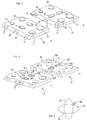
- Figure 1 schematically represents a prospective view of a cooking hob of the type substantially known; in such figure the reference number 1 indicates as a whole a domestic cooking hob; reference number 2 indicates a so called fish-pan gas burner, centrally arranged respects the hob 1 and being of an elongated form.
- Reference numbers 3, 4, 5 and 6 indicate four gas burners of the normal type, being of different dimensions and heat power, that can be used for the needs of pots, frying pans and saucepans of different dimensions, for the cooking of different types of foodstuffs; such burners 3-6 are arranged laterally compared to the fish-pan burner 2 and are circular. Finally, reference number 7 indicates the commands, or cocks, of the single burners 2-6.
- the fish-pan burner occupies a substantial part of the cooking hob; as previously mentioned, apart from reducing the useful space of the cooking hob, the fish-pan burner 2 determines considerable rigidity of use of the hob 1, be it from the point of view of the types of pans that are to be used, and also from the usable heat power.
- burners 11 and 12 are indicated, realized according to substantially known techniques; for instance such burners may have a lower sump, a main body, inserted over the sump, comprising air-gas mixing means (for instance in the form of a Venturi type tube), and an upper flame divider.
- the burners 11 and 12 may indifferently be of the type that withdraw the primary air from above or below the hob on which they are mounted.
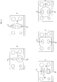
- the upper part of the burners 11 and 12 have a generally elongated form, being substantially elliptical; in the parts A of such figures, the two burners 11 and 12 are longitudinally arranged one to the other.
- the burners 11 and 12 are realized in such a way that they can be rotated to 90°, as is clear in part B of figures 2 and 3, wherein the flame dividers of the two burners in fact result in being arranged in a parallel manner one to the other.
- Such rotation can be obtained in various ways, according to the chosen embodiment of the sump and body of the burners 11 and 12; for instance the rotation could be obtained:
- the two burners 11 and 12 are also realized so as to be sure that the relative flame crowns do not create functional interference; in other words the burners 11 and 12 are apt at creating a smaller flame in correspondence of the eventual proximity points (fig. 2 - parts C and D); this can be obtained by appropriately realising the body of the burner and/or the relative flame divider, so that the passages from which the air-gas mixture exits are calibrated so as to generate a flame of reduced dimensions in correspondence of the two extremities of each burner.
- the burners 11 and 12 are separately controlled by way of two distinct cocks, indicated with 18 and 19.
- Other control solutions of the gas supply are possible: for instance a single stepped cock, that allows for the contemporary or separate functioning of the two burners.
- the cooking hob according to the invention has a flexibility of use considerably improved in respect of the cooking hob of figure 1.
- figure 4 illustrates several possible utilisations of the cooking hob 10.
- burners 11 and 12 are both in use and longitudinally positioned, for the heating of an oval pan for fish, indicated with 20; such use of burners 11 and 12 therefore allows for obtaining the same results as those obtained by the fish-pan burner 2 of figure 1, according to the known art.
- burners 11 and 12 are both positioned longitudinally, but only burner 12 is in use and is being utilized for heating a round saucepan of medium dimensions, indicated with 21.
- the burners 11 and 12 are arranged in a parallel manner and both are in use, but in this case they are used for heating two pots or pans of smaller dimensions, indicated with 24 and 25; of course, in the case of part E of figure 4, also only one of the two burners 11 and 12 could be used, for heating a single pan of a small diameter.
- the cooking hob 10 will be equipped with a grid, or a system of multi grids cooperating one with the other, not represented for simplicity, realized so as to support containers of different shapes and sizes, for instance according to the cases illustrated in figure 4 (containers being oval and round, of small, medium and large diameters, square, rectangular, etc.).
- the cooking hob according to the invention also has the advantage of offering the possibility of cooking in an optimal manner also foodstuffs contained in square or rectangular pans.
- FIG. 5 A first possible variant embodiment of the present invention is illustrated in figure 5, in which some of the previously mentioned reference numbers are used.
- the reference numbers 30 and 31 indicate as a whole two gas burners having in substance the functions of those indicated with 11 and 12 in figure 2, and therefore being realized in such a way as to be able to modify their working position.
- Such burners 30 and 31 are realized according to the techniques described in Italian Patent n° 1.232.887 ( corresponding to FR-A-2,650,369 ), in the name of the same Applicant, in the sense that each of the burners 30 and 31 comprises a couple of concentric burners; in particular with 30A and 31A the internal burners are indicated, apt at producing a central flame crown of reduced dimensions; with 30B and 31B, the external burners are indicated, apt at producing two peripheral flame semi-crowns; the distinct controls of the four burners 30A, 30B, 31A and 31B are indicated with 32.
- the cooking hob 10 illustrated in figure 5 has a flexibility of use which is further improved, which ranges from a limited heat output (i.e. use of the single burner 30A) to a very high output (i.e. the use of all four burners 30A, 30B, 31A and 31B simultaneously).
- the burners 11 and 12 are equipped with an ignition lighting system, for instance of the piezoelectric type, with a relative thermocouple, for verifying whether the burner is alight or not; in figure 6 a particularly advantageous disposition is illustrated of the ignition lighter, indicated with 40, and of the relative thermocouple 41; as can be seen, even though the burner 11 is able to assume the two previously mentioned working positions, 90° one from the other, the ignition lighter 40 and the thermocouple 41, are arranged in position that allow for an ever correct functioning of the lighting system; as can in fact be seen, the relative distances between said elements 40 and 41 (fixed elements) and the burner 11 (movable element), are in substance always the same, independently from the working position chosen for the burner 11.
- Another possible variant is that of equipping the burners 11 and 12 of figures 2 and 3 with a sensor of the temperature reached by the foodstuffs being cooked, with the aims of an automatic control of the actual temperature; such sensor could in fact be realized according to that described in Italian Patent n° 1.178.820 ( corresponding to US 4,646,963 ), in the case of burners that withdraw the primary air from below the cooking hob, or of the type described in Italian Patent n° 1.233.204 ( corresponding to EP-A-392,523 ), in the case of burners that withdraw the primary air from above the cooking hob.
- it is also possible to equip the burners with a device for compensating the influence of external heat sources on the temperature sensor for example of the type described in Italian Patent n° 1.179.564 ( corresponding to US 4,645,124 ).
- the burners 11 and 12 could be of the double flame crown type, such as the type described in the Italian Patent Application n° TO91A000723 ( corresponding to EP-A-534,301 ) in the name of the same applicant.
- Another variant could be that of providing for the cooking hob supporting grids of the cooking containers of the interchangeable type, or with the possibility different positionings, in measure with the burners 11 and 12, according to the arrangement and use of said burners.
Landscapes
- Engineering & Computer Science (AREA)
- Chemical & Material Sciences (AREA)
- Combustion & Propulsion (AREA)
- Mechanical Engineering (AREA)
- General Engineering & Computer Science (AREA)
- Gas Burners (AREA)
- Baking, Grill, Roasting (AREA)
- Cookers (AREA)
Priority Applications (1)
| Application Number | Priority Date | Filing Date | Title |
|---|---|---|---|
| EP99204365A EP0995950B1 (fr) | 1994-04-08 | 1995-04-04 | Plaque de cuisson avec brûleur à gaz à position variable |
Applications Claiming Priority (2)
| Application Number | Priority Date | Filing Date | Title |
|---|---|---|---|
| ITTO940261A IT1273116B (it) | 1994-04-08 | 1994-04-08 | Piano di cottura domestico, con bruciatori di gas ad assetto variabile |
| ITTO940261 | 1994-04-08 |
Related Child Applications (1)
| Application Number | Title | Priority Date | Filing Date |
|---|---|---|---|
| EP99204365A Division EP0995950B1 (fr) | 1994-04-08 | 1995-04-04 | Plaque de cuisson avec brûleur à gaz à position variable |
Publications (3)
| Publication Number | Publication Date |
|---|---|
| EP0676591A2 true EP0676591A2 (fr) | 1995-10-11 |
| EP0676591A3 EP0676591A3 (fr) | 1997-02-12 |
| EP0676591B1 EP0676591B1 (fr) | 2000-09-27 |
Family
ID=11412434
Family Applications (2)
| Application Number | Title | Priority Date | Filing Date |
|---|---|---|---|
| EP95105004A Expired - Lifetime EP0676591B1 (fr) | 1994-04-08 | 1995-04-04 | Plaque de cuisson avec brûleur à gaz à position variable |
| EP99204365A Expired - Lifetime EP0995950B1 (fr) | 1994-04-08 | 1995-04-04 | Plaque de cuisson avec brûleur à gaz à position variable |
Family Applications After (1)
| Application Number | Title | Priority Date | Filing Date |
|---|---|---|---|
| EP99204365A Expired - Lifetime EP0995950B1 (fr) | 1994-04-08 | 1995-04-04 | Plaque de cuisson avec brûleur à gaz à position variable |
Country Status (4)
| Country | Link |
|---|---|
| EP (2) | EP0676591B1 (fr) |
| DE (2) | DE69518939T2 (fr) |
| ES (2) | ES2151564T3 (fr) |
| IT (1) | IT1273116B (fr) |
Cited By (4)
| Publication number | Priority date | Publication date | Assignee | Title |
|---|---|---|---|---|
| EP0848211A1 (fr) * | 1996-12-10 | 1998-06-17 | SMEG S.p.A. | Plaque de cuisson à brûleurs pour usage combiné |
| WO2007107195A1 (fr) * | 2006-03-23 | 2007-09-27 | Steel Time S.R.L. | Brûleur modulaire pour une plaque de cuisson |
| WO2008080804A3 (fr) * | 2006-12-29 | 2008-11-06 | Arcelik As | Cuisinière |
| EP3268667B1 (fr) * | 2015-03-10 | 2020-11-18 | E.G.O. Elektro-Gerätebau GmbH | Brûleur à gaz perfectionné |
Families Citing this family (2)
| Publication number | Priority date | Publication date | Assignee | Title |
|---|---|---|---|---|
| DE102013218852A1 (de) * | 2013-09-19 | 2015-03-19 | E.G.O. Elektro-Gerätebau GmbH | Anordnung von Gasbrennern |
| CN105387490A (zh) * | 2015-11-26 | 2016-03-09 | 王本 | 一种适用于烹饪鱼类的燃气灶 |
Family Cites Families (2)
| Publication number | Priority date | Publication date | Assignee | Title |
|---|---|---|---|---|
| DE826060C (de) * | 1950-11-22 | 1951-12-27 | Dr Rudolf Schmitz | Mehrflammiger Gaskocher |
| DE8709333U1 (de) * | 1987-07-07 | 1987-09-10 | Beyer, Hans-Jörgen, 7406 Mössingen | Wärmeleitplatte |
-
1994
- 1994-04-08 IT ITTO940261A patent/IT1273116B/it active IP Right Grant
-
1995
- 1995-04-04 EP EP95105004A patent/EP0676591B1/fr not_active Expired - Lifetime
- 1995-04-04 ES ES95105004T patent/ES2151564T3/es not_active Expired - Lifetime
- 1995-04-04 EP EP99204365A patent/EP0995950B1/fr not_active Expired - Lifetime
- 1995-04-04 ES ES99204365T patent/ES2168834T3/es not_active Expired - Lifetime
- 1995-04-04 DE DE69518939T patent/DE69518939T2/de not_active Expired - Fee Related
- 1995-04-04 DE DE69525079T patent/DE69525079T2/de not_active Expired - Fee Related
Cited By (5)
| Publication number | Priority date | Publication date | Assignee | Title |
|---|---|---|---|---|
| EP0848211A1 (fr) * | 1996-12-10 | 1998-06-17 | SMEG S.p.A. | Plaque de cuisson à brûleurs pour usage combiné |
| WO2007107195A1 (fr) * | 2006-03-23 | 2007-09-27 | Steel Time S.R.L. | Brûleur modulaire pour une plaque de cuisson |
| US7967004B2 (en) | 2006-03-23 | 2011-06-28 | Steel Time S.P.A. | Modular burner for a cooking plate |
| WO2008080804A3 (fr) * | 2006-12-29 | 2008-11-06 | Arcelik As | Cuisinière |
| EP3268667B1 (fr) * | 2015-03-10 | 2020-11-18 | E.G.O. Elektro-Gerätebau GmbH | Brûleur à gaz perfectionné |
Also Published As
| Publication number | Publication date |
|---|---|
| EP0995950A3 (fr) | 2000-05-24 |
| ES2168834T3 (es) | 2002-06-16 |
| DE69518939T2 (de) | 2001-02-08 |
| DE69518939D1 (de) | 2000-11-02 |
| EP0676591B1 (fr) | 2000-09-27 |
| DE69525079T2 (de) | 2002-06-20 |
| ES2151564T3 (es) | 2001-01-01 |
| EP0995950B1 (fr) | 2001-11-21 |
| EP0995950A2 (fr) | 2000-04-26 |
| EP0676591A3 (fr) | 1997-02-12 |
| DE69525079D1 (de) | 2002-02-21 |
| ITTO940261A0 (it) | 1994-04-08 |
| IT1273116B (it) | 1997-07-04 |
| ITTO940261A1 (it) | 1995-10-08 |
Similar Documents
| Publication | Publication Date | Title |
|---|---|---|
| US7527495B2 (en) | Cooperating bridge burner system | |
| US9557063B2 (en) | Burner assembly for cooktop appliance and method for operating same | |
| US10816215B2 (en) | Diffusion cap burner for gas cooking appliance | |
| CA2302457C (fr) | Bruleurs avec orifices de commande | |
| US9119500B2 (en) | Griddle plate for a gas grill | |
| US4313416A (en) | Wok burner | |
| KR100936150B1 (ko) | 버너 및 이를 포함하는 조리기기 | |
| KR101220550B1 (ko) | 가스레인지 | |
| EP3552528B1 (fr) | Barbecue à gaz | |
| US6017211A (en) | Rotatable gas burner system for a range or cooktop | |
| EP0995950B1 (fr) | Plaque de cuisson avec brûleur à gaz à position variable | |
| CA2690412A1 (fr) | Tableau de commande frontal pour cuisinuiere a gaz | |
| MXPA06009873A (es) | Plancha de coccion de combustion a gas. | |
| AU2014377392A1 (en) | Gas heating arrangement and method for operating a gas heating arrangement | |
| EP1508001B1 (fr) | Assemblage pour gazinières comprenant un brûleur à gaz et un support pour récipient | |
| EP2301397B1 (fr) | Réducteur de flammes et agencement associé pour les grills de barbecue | |
| EP0677705B1 (fr) | Brûleur à gaz à position variable et plaque de cuisson | |
| US20070151556A1 (en) | Gas fired cooktop and method of assembling the same | |
| US20030085222A1 (en) | Cooking appliance | |
| CA2537623A1 (fr) | Surface de cuisson au gas et methode d'assemblage | |
| US10948181B2 (en) | Multi-level gas burner having ultra low simmer | |
| GB2292453A (en) | Cooking gas burner | |
| KR20200001965U (ko) | 복수개의 연소기를 가지는 로스터 | |
| KR200196668Y1 (ko) | 가스레인지 겸용 고기구이기 | |
| KR200450330Y1 (ko) | 휴대용 가스렌지 |
Legal Events
| Date | Code | Title | Description |
|---|---|---|---|
| PUAI | Public reference made under article 153(3) epc to a published international application that has entered the european phase |
Free format text: ORIGINAL CODE: 0009012 |
|
| AK | Designated contracting states |
Kind code of ref document: A2 Designated state(s): DE ES FR GB IT |
|
| PUAL | Search report despatched |
Free format text: ORIGINAL CODE: 0009013 |
|
| AK | Designated contracting states |
Kind code of ref document: A3 Designated state(s): DE ES FR GB IT |
|
| 17P | Request for examination filed |
Effective date: 19970731 |
|
| 17Q | First examination report despatched |
Effective date: 19980911 |
|
| RAP1 | Party data changed (applicant data changed or rights of an application transferred) |
Owner name: MERLONI ELETTRODOMESTICI S.P.A. |
|
| GRAG | Despatch of communication of intention to grant |
Free format text: ORIGINAL CODE: EPIDOS AGRA |
|
| GRAG | Despatch of communication of intention to grant |
Free format text: ORIGINAL CODE: EPIDOS AGRA |
|
| GRAH | Despatch of communication of intention to grant a patent |
Free format text: ORIGINAL CODE: EPIDOS IGRA |
|
| GRAG | Despatch of communication of intention to grant |
Free format text: ORIGINAL CODE: EPIDOS AGRA |
|
| GRAH | Despatch of communication of intention to grant a patent |
Free format text: ORIGINAL CODE: EPIDOS IGRA |
|
| GRAA | (expected) grant |
Free format text: ORIGINAL CODE: 0009210 |
|
| ITF | It: translation for a ep patent filed | ||
| AK | Designated contracting states |
Kind code of ref document: B1 Designated state(s): DE ES FR GB IT |
|
| REF | Corresponds to: |
Ref document number: 69518939 Country of ref document: DE Date of ref document: 20001102 |
|
| ET | Fr: translation filed | ||
| REG | Reference to a national code |
Ref country code: ES Ref legal event code: FG2A Ref document number: 2151564 Country of ref document: ES Kind code of ref document: T3 |
|
| PLBE | No opposition filed within time limit |
Free format text: ORIGINAL CODE: 0009261 |
|
| STAA | Information on the status of an ep patent application or granted ep patent |
Free format text: STATUS: NO OPPOSITION FILED WITHIN TIME LIMIT |
|
| 26N | No opposition filed | ||
| REG | Reference to a national code |
Ref country code: GB Ref legal event code: IF02 |
|
| PGFP | Annual fee paid to national office [announced via postgrant information from national office to epo] |
Ref country code: ES Payment date: 20080507 Year of fee payment: 14 Ref country code: DE Payment date: 20080506 Year of fee payment: 14 |
|
| PG25 | Lapsed in a contracting state [announced via postgrant information from national office to epo] |
Ref country code: DE Free format text: LAPSE BECAUSE OF NON-PAYMENT OF DUE FEES Effective date: 20091103 |
|
| REG | Reference to a national code |
Ref country code: ES Ref legal event code: FD2A Effective date: 20090406 |
|
| PG25 | Lapsed in a contracting state [announced via postgrant information from national office to epo] |
Ref country code: ES Free format text: LAPSE BECAUSE OF NON-PAYMENT OF DUE FEES Effective date: 20090406 |
|
| PGFP | Annual fee paid to national office [announced via postgrant information from national office to epo] |
Ref country code: FR Payment date: 20120510 Year of fee payment: 18 Ref country code: GB Payment date: 20120425 Year of fee payment: 18 |
|
| GBPC | Gb: european patent ceased through non-payment of renewal fee |
Effective date: 20130404 |
|
| PG25 | Lapsed in a contracting state [announced via postgrant information from national office to epo] |
Ref country code: GB Free format text: LAPSE BECAUSE OF NON-PAYMENT OF DUE FEES Effective date: 20130404 |
|
| REG | Reference to a national code |
Ref country code: FR Ref legal event code: ST Effective date: 20131231 |
|
| PG25 | Lapsed in a contracting state [announced via postgrant information from national office to epo] |
Ref country code: FR Free format text: LAPSE BECAUSE OF NON-PAYMENT OF DUE FEES Effective date: 20130430 |
|
| PGFP | Annual fee paid to national office [announced via postgrant information from national office to epo] |
Ref country code: IT Payment date: 20140430 Year of fee payment: 20 |