EP0676605A1 - Formlingsträger für zu trocknende keramische Formlinge, wie Hochlochziegel od.dgl. und Formlings(träger)-Anordnung - Google Patents
Formlingsträger für zu trocknende keramische Formlinge, wie Hochlochziegel od.dgl. und Formlings(träger)-Anordnung Download PDFInfo
- Publication number
- EP0676605A1 EP0676605A1 EP95105474A EP95105474A EP0676605A1 EP 0676605 A1 EP0676605 A1 EP 0676605A1 EP 95105474 A EP95105474 A EP 95105474A EP 95105474 A EP95105474 A EP 95105474A EP 0676605 A1 EP0676605 A1 EP 0676605A1
- Authority
- EP
- European Patent Office
- Prior art keywords
- support
- profile
- blank
- carrier
- support according
- Prior art date
- Legal status (The legal status is an assumption and is not a legal conclusion. Google has not performed a legal analysis and makes no representation as to the accuracy of the status listed.)
- Granted
Links
- 239000000919 ceramic Substances 0.000 title claims description 6
- 229910000831 Steel Inorganic materials 0.000 claims abstract description 5
- 239000010959 steel Substances 0.000 claims abstract description 5
- 239000011449 brick Substances 0.000 claims abstract description 3
- 238000000465 moulding Methods 0.000 claims description 29
- 238000001035 drying Methods 0.000 claims description 9
- 239000011470 perforated brick Substances 0.000 claims description 9
- 239000000969 carrier Substances 0.000 claims description 3
- 238000007664 blowing Methods 0.000 claims description 2
- 238000004519 manufacturing process Methods 0.000 claims description 2
- 125000006850 spacer group Chemical group 0.000 claims 1
- 230000004308 accommodation Effects 0.000 abstract 1
- 230000007797 corrosion Effects 0.000 description 1
- 238000005260 corrosion Methods 0.000 description 1
- 238000011161 development Methods 0.000 description 1
- 230000018109 developmental process Effects 0.000 description 1
- 239000000463 material Substances 0.000 description 1
Images
Classifications
-
- F—MECHANICAL ENGINEERING; LIGHTING; HEATING; WEAPONS; BLASTING
- F26—DRYING
- F26B—DRYING SOLID MATERIALS OR OBJECTS BY REMOVING LIQUID THEREFROM
- F26B25/00—Details of general application not covered by group F26B21/00 or F26B23/00
- F26B25/06—Chambers, containers, or receptacles
- F26B25/14—Chambers, containers, receptacles of simple construction
- F26B25/18—Chambers, containers, receptacles of simple construction mainly open, e.g. dish, tray, pan, rack
-
- F—MECHANICAL ENGINEERING; LIGHTING; HEATING; WEAPONS; BLASTING
- F26—DRYING
- F26B—DRYING SOLID MATERIALS OR OBJECTS BY REMOVING LIQUID THEREFROM
- F26B15/00—Machines or apparatus for drying objects with progressive movement; Machines or apparatus with progressive movement for drying batches of material in compact form
- F26B15/10—Machines or apparatus for drying objects with progressive movement; Machines or apparatus with progressive movement for drying batches of material in compact form with movement in a path composed of one or more straight lines, e.g. compound, the movement being in alternate horizontal and vertical directions
- F26B15/12—Machines or apparatus for drying objects with progressive movement; Machines or apparatus with progressive movement for drying batches of material in compact form with movement in a path composed of one or more straight lines, e.g. compound, the movement being in alternate horizontal and vertical directions the lines being all horizontal or slightly inclined
- F26B15/14—Machines or apparatus for drying objects with progressive movement; Machines or apparatus with progressive movement for drying batches of material in compact form with movement in a path composed of one or more straight lines, e.g. compound, the movement being in alternate horizontal and vertical directions the lines being all horizontal or slightly inclined the objects or batches of materials being carried by trays or racks or receptacles, which may be connected to endless chains or belts
Definitions
- the invention relates to a molding carrier for receiving air-flowable ceramic moldings to be dried for the manufacture of masonry brick, in particular perforated brick.
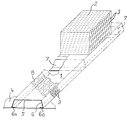
- an embodiment of the invention is shown schematically. It shows a perspective view of a molding carrier according to the invention with a perforated brick placed thereon, the channels of which run parallel to the floor.
- a molding carrier 1 according to the invention is used for receiving air-flowable ceramic moldings to be dried, in particular so-called.
- Perforated bricks which are numbered as a whole with 2 and their holes / channels with 3.
- Such a molded carrier 1 is preferably arranged on a closed base 4, which is transported through a tunnel dryer (not shown).
- the molding carrier 1 has a stiffened carrier profile made of sheet steel in the form of an upside-down (inverted) U, the U-web 5 and U-legs 6 are perforated.
- the proportion of holes in the respective area is about 35 - 65%.
- the U-web 5 of the carrier profile forms a mold receptacle (surface) through which air can flow and is dimensioned such that a plurality of moldings 2 can be lined up next to one another in the longitudinal direction of the mold carrier.
- the U-web 5 has a length that approximately corresponds to the length of the molding 2 to be received (see drawing).
- the molded carrier 1 has a cross section which widens towards the bottom. This cross section preferably lies on a symmetrical trapezoid.
- both U-legs 6 can be beveled towards the plane of symmetry, ie inwards (cf. item 6a in the drawing).
- the U-profile is stiffened in cross section by means of struts 7 arranged at a distance from one another.
- the struts 7 are welded to the U-legs 6 and support the U-web 5.
- the proportion of holes in the U-web 5 is dimensioned as large as possible, but depending on the material of the molded articles 2 to be dried, it is designed such that sufficient support is provided for the molded article 2 to be dried and disadvantageous impressions are avoided.
- the perforation of the U-web 5 forming the blanket (surface) consists of elongated holes 8. These elongated holes 8 have a width of 15-30 mm and a length of 40-70 mm.
- the elongated holes 8 are burr-free on the outer surface, in particular rounded off in the edge area, and the elongated longitudinal axis is provided in the longitudinal direction of the molded carrier 1 (see drawing).
- the elongated hole alignment in the longitudinal direction of the shaped carrier enables faster pushing off - without disadvantageous side effects - than a transverse position allows.
- the elongated holes 8 are arranged offset from one another. This avoids that a molding 2 to be removed can tilt / hook.
- An arrangement is particularly preferred in which the elongated holes run in rows one behind the other and the individual rows of elongated holes are in a gap (cf. drawing), ie are preferably offset by 1/2 grid dimension.
- the perforation in the U-legs 6, which act as set-up elements, is numbered 9. According to the drawing, round holes are preferred, but elongated holes can also be provided.
- the perforation 9 is carried out in such a way that a back pressure builds up in front of the molded carrier 1 when there is an air flow through the carrier profile. Because of this dynamic pressure, a uniform air flow is ensured, and a deflection of air blown against the end faces / cut surfaces of the molded articles 2 (drying air) is favored / achieved.
- the holes have a diameter of approximately 8-16 mm, preferably approximately 12 m.
- the length of the molding carrier 1 is dimensioned so that several moldings 2 can be arranged side by side.
- the shaped carrier length can be more than 5 m, but preferably less than 6 m.
- At least the carrier profile of the molded carrier 1 is preferably made of galvanized sheet steel.
- the moldings 2 are arranged in one layer on the mold carriers 1 in such a way that the mold channels 3 extend transversely to the mold carrier strand direction and the drying air against the perforated end faces (cut surfaces) of the moldings 2 and the U-leg 6 of a molding carrier 1 is blown.
- perforated brick moldings 2 are directionally blown and evenly flowed around and through. It is particularly advantageous if the perforated brick moldings 2 to be dried are first directed (targeted) over the entire surface from the front and then from the rear - there is no excessive drying of the edges relative to the drying inside the perforated brick molding 2.
Landscapes
- Engineering & Computer Science (AREA)
- Mechanical Engineering (AREA)
- General Engineering & Computer Science (AREA)
- Drying Of Solid Materials (AREA)
- Furnace Charging Or Discharging (AREA)
- Compositions Of Oxide Ceramics (AREA)
- Processing And Handling Of Plastics And Other Materials For Molding In General (AREA)
- Devices For Post-Treatments, Processing, Supply, Discharge, And Other Processes (AREA)
Abstract
Description
- Die Erfindung betrifft einen Formlingsträger zur luftumströmbaren Aufnahme von zu trocknenden keramischen Formlingen für die Mauerziegel-Fertigung, insbesondere Hochlochziegel.
- Derartige Formlingsträger sind in der Praxis in verschiedenen Ausführungsformen bekanntgeworden. Trotz der vielen Varianten mangelt es an einem System, mit welchem eine energiesparende, schnelle und schonende Trocknung von gittersteinartigen Keramikformlingen, insbesondere sogen. Hochlochziegeln gewährleistet wird.
- Es ist daher Aufgabe der Erfindung, für die schonende Schnelltrocknung von Keramikformlingen in der Art von Hochlochziegeln einen Formlingsträger zu schaffen, welcher die zu trocknenden Formlinge im erforderlichen Maße unterstützt und trotzdem eine gute Luftanströmung des Formlings gewährleistet sowie für gleichmäßige Luftdurchströmung sorgt.
- Diese Aufgabe wird durch einen Formlingsträger gemäß Anspruch 1 gelöst. Vorteilhafte Weiterbildungen ergeben sich aus den Unteransprüchen. Der Nebenanspruch 13 ergibt ein vorteilhaftes Beblasungs- oder Luftführungssystem.
- Auf der Zeichnung ist ein Ausführungsbeispiel der Erfindung schematisch dargestellt. Sie zeigt in perspektivischer Darstellung einen erfindungsgemäßen Formlingsträger mit einem darauf aufgesetzten Hochlochziegel, dessen Kanäle bodenparallel verlaufen.
- Ein erfindungsgemäßer Formlingsträger 1 dient der luftumströmbaren Aufnahme von zu trocknenden keramischen Formlingen, insbesondere sogen. Hochlochziegeln, welche als Ganzes mit 2 und deren Löcher/Kanäle mit 3 beziffert sind. In bevorzugter Weise ist ein solcher Formlingsträger 1 auf einer geschlossenen Unterlage 4 angeordnet, welche durch einen Tunneltrockner (nicht dargestellt) transportiert wird.
- Der Formlingsträger 1 weist ein ausgesteiftes Trägerprofil aus Stahlblech in Form eines kopfstehenden (umgekehrten) U auf, dessen U-Steg 5 und U-Schenkel 6 gelocht sind. Der Loch-Anteil an der jeweiligen Fläche beträgt etwa 35 - 65 %.
- Der U-Steg 5 des Trägerprofils bildet eine luftdurchströmbare Formlingsaufnahme(fläche) und ist so bemessen, daß in Formlingsträger-Längsrichtung eine Vielzahl von Formlingen 2 nebeneinander aufreihbar sind. Im Profil-Querschnitt des Formlingsträgers weist der U-Steg 5 eine Länge auf, die annähernd der Länge des aufzunehmenden Formlings 2 entspricht (vgl. Zeichnung).
- Zur Erzielung einer größeren Standfestigkeit weist der Formlingsträger 1 einen sich bodenwärts erweiternden Querschnitt auf. In bevorzugter Weise liegt dieser Querschnitt auf einem symmetrischen Trapez.
- Die freien Enden beider U-Schenkel 6 können zur Symmetrieebene, d.h. nach innen abgekantet sein (vgl. Pos. 6a in der Zeichnung).
- Das U-Profil ist querschnittsmäßig mittels im Abstand zueinander angeordneter Streben 7 ausgesteift. Die Streben 7 sind an den U-Schenkeln 6 angeschweißt und unterstützen den U-Steg 5.
- Der Lochanteil des U-Stegs 5 ist möglichst groß bemessen, jedoch in Abhängigkeit vom Material der zu trocknenden Formlinge 2 derart ausgeführt, daß für den zu trocknenden Formling 2 ausreichende Unterstützung erfolgt und nachteilige Abdrücke vermieden werden.
- In bevorzugter Weise besteht die Lochung des die Formlingsauflage(fläche) bildenden U-Stegs 5 aus Langlöchern 8. Diese Langlöcher 8 haben eine Breite von 15 - 30 mm sowie eine Länge von 40 - 70 mm.
- Um ein hemmfreies, d.h. leichtes Abschieben der Formlinge 2 in Trägerprofil-Längsrichtung zu ermöglichen, sind die Langlöcher 8 an der außenliegenden Oberfläche gratfrei, insbesonders im Randbereich abgerundet ausgebildet sowie die Langloch-Längsachse in Längsrichtung des Formlingsträgers 1 vorgesehen (vgl. Zeichnung). Die Langloch-Ausrichtung in Formlingsträger-Längsrichtung ermöglicht ein schnelleres Abschieben - ohne nachteilige Nebenwirkungen - als es eine Querlage erlaubt.
- Die Langlöcher 8 sind gegeneinander versetzt angeordnet. Dadurch wird vermieden, daß ein abzuschiebender Formling 2 verkanten/anhaken kann.
- Besonders bevorzugt ist dabei eine Anordnung, bei welcher die Langlöcher in Reihen hintereinander verlaufen sowie die einzelnen Langloch-Reihen auf Lücke stehen (vgl. Zeichnung), d.h. vorzugsweise um 1/2 Rastermaß versetzt sind.
- Die Lochung in den als Aufstellelemente fungierenden U-Schenkeln 6 ist mit 9 beziffert. Entsprechend zeichnerischer Darstellung sind dabei Rundlöcher bevorzugt, es können jedoch auch Langlöcher vorgesehen sein. Die Lochung 9 ist dabei derart ausgeführt, daß bei einer Luftströmung durch das Trägerprofil vor dem Formlingsträger 1 sich ein Staudruck aufbaut. Aufgrund dieses Staudrucks ist eine vergleichmäßigte Luftströmung gewährleistet, und außerdem wird eine Umlenkung von gegen die Stirnflächen/Schnittflächen der Formlinge 2 geblasener Luft (Trocknungsluft) begünstigt/erzielt.
- Bei Rundloch-Ausführung der Lochung 9 haben die Löcher einen Durchmesser von etwa 8 - 16 mm, vorzugsweise etwa 12 m.
- Die Länge des Formlingsträgers 1 ist so bemessen, daß mehrere Formlinge 2 nebeneinander angeordnet werden können. Die Formlingsträger-Länge kann dabei über 5 m, vorzugsweise jedoch unter 6 m, betragen.
- Um einen guten Korrosionsschutz zu gewährleisten, besteht zumindest das Trägerprofil des Formlingsträgers 1 vorzugsweise aus verzinktem Stahlblech.
- Eine vorteilhafte Schnelltrocknung der zu trocknenden Formlinge 2 ist gegeben, wenn die Formlinge 2 einlagig auf den Formlingsträgern 1 in solcher Aufstellweise angeordnet werden, daß die Formlingskanäle 3 sich quer zur Formlingsträger-Strangrichtung erstrecken und die Trocknungsluft gegen die gelochten Stirnflächen (Schnittflächen) der Formlinge 2 sowie der U-Schenkel 6 eines Formlingsträgers 1 geblasen wird.
Dabei werden Lochziegel-Formlinge 2 gerichtet beblasen sowie gleichmäßig umströmt und durchströmt. Besonders vorteilhaft ist es, wenn die zu trocknenden Lochziegel-Formlinge 2 zunächst gerichtet (gezielt) ganzflächig von vorne und dann von hinten beblasen werden - es findet dabei keine zu starke Trocknung der Ränder relativ zur Trocknung im Innern des Lochziegel-Formlings 2 statt. -
- 1
- Formlingsträger
- 2
- Formling
- 3
- Formlingskanäle
- 4
- Unterlage für 1
- 5
- U-Steg von 1 (Tragfläche)
- 6
- U-Schenkel (Aufstellwandungen)
- 6a
- Abkantung von 6
- 7
- Streben im Profil von 1
- 8
- Langlöcher in 5
- 9
- Lochung in 6
Claims (14)
- Formlingsträger zur luftumströmbaren Aufnahme von zu trocknenden keramischen Formlingen für die Mauerziegel-Fertigung, insbesondere Hochlochziegel, mit den Merkmalen:a) er weist ein ausgesteiftes Trägerprofil aus Stahlblech in Form eines kopfstehenden U auf, dessen U-Steg (5) und U-Schenkel (6) gelocht sind, wobei der Loch-Anteil an der jeweiligen Fläche 35 - 65 % beträgt,b) der U-Steg (5) des Trägerprofils bildet eine luftdurchströmbare Formlingsaufnahme(fläche) und ist so bemessen, daß in Formlingsträger-Längsrichtung eine Vielzahl von Formlingen (2) nebeneinander aufreihbar sind,c) im Profil-Querschnitt weist der U-Steg (5) eine Länge auf, die annähernd der Länge des aufzunehmenden Mauerziegel-Formlings (2) entspricht, undd) die Lochung (9) in den als Aufstellelemente fungierenden U-Schenkeln (6) ist derart ausgebildet, daß bei einer Luftströmung durch das Trägerprofil vor demselben sich ein Staudruck aufbaut.
- Formlingsträger nach Anspruch 1, dadurch gekennzeichnet daß er einen sich bodenwärts erweiternden Querschnitt aufweist.
- Formlingsträger nach Anspruch 2, dadurch gekennzeichnet, daß das Trägerprofil im Querschnitt als symmetrisches Trapez ausgebildet ist.
- Formlingsträger nach mindestens einem der Ansprüche 1 bis 3, dadurch gekennzeichnet, daß die Lochung der Formlingsauflage(fläche) aus Langlöchern (8) besteht, deren Längsachse in Längsrichtung des Trägerprofils verläuft.
- Formlingsträger nach mindestens einem der Ansprüche 1 bis 4, dadruch gekennzeichnet, daß benachbarte Langlöcher (8) zumindest in der Trägerprofil-Querrichtung gegen-einander versetzt sind.
- Formlingsträger nach Anspruch 5, dadruch gekennzeichnet, daß die Langlöcher (8) in Reihen hintereinander angeordnet sowie auf Lücke stehend versetzt sind.
- Formlingsträger nach mindestens einem der Ansprüche 1 bis 6, dadurch gekennzeichnet, daß die Langlöcher (8) der Formlingsauflage(fläche) eine Breite von 15 - 30 mm sowie eine Länge von 40 - 70 mm haben.
- Formlingsträger nach mindestens einem der Ansprüche 1 bis 7, dadurch gekennzeichnet, daß die Langlöcher (8) der Formlingsauflage(fläche) (5) an der außenliegenden Oberfläche gratfrei/abgerundet ausgebildet sind.
- Formlingsträger nach mindestens einem der Ansprüche 1 bis 8, dadurch gekennzeichnet, daß der Lochanteil in den als Aufstellwände bzw. Abstandshalter fungierenden Wandungen, insbesondere U-Schenkeln (6) des U-Profils, 50 - 55 % beträgt.
- Formlingsträger nach mindestens einem der Ansprüche 1 bis 9, dadurch gekennzeichnet, daß das U-Profil mittels im Abstand zueinander angeordneter Streben (7) ausgesteift ist.
- Formlingsträger nach Anspruch 10, dadurch gekennzeichnet daß die Streben (7) an den U-Schenkeln (6) angeschweißt sind und den U-Steg höhenmäßig unterstützen (abstützen).
- Formlingsträger nach mindestens einem der Ansprüche 1 bis 11, dadurch gekennzeichnet, daß zumindest sein Trägerprofil aus verzinktem Stahlblech besteht.
- Anordnung eines Formlings(trägers), insbesondere nach Anspruch 1, dadurch gekennzeichnet, daß derselbe (1) auf geschlossener Unterlage/Transport-Unterlage (4), insbesondere Trocknerwagen eines Tunneltrockners, derart angeordnet ist, daß sich seine Längsachse quer zur Blasrichtung von ausgedüster Trocknungsluft erstreckt.
- Anordnung nach Anspruch 13, dadurch gekennzeichnet, daß die Formlingsträger-Längsache sich quer zur Transportrichtung erstreckt und die seitlichen Lochwandungen (6) des Profilquerschnitts von aus einer Breitstrahldüse ausgedüster Trocknungsluft beblasen wird (beblasbar ist).
Applications Claiming Priority (2)
| Application Number | Priority Date | Filing Date | Title |
|---|---|---|---|
| DE4412356 | 1994-04-11 | ||
| DE4412356 | 1994-04-11 |
Publications (2)
| Publication Number | Publication Date |
|---|---|
| EP0676605A1 true EP0676605A1 (de) | 1995-10-11 |
| EP0676605B1 EP0676605B1 (de) | 1998-01-14 |
Family
ID=6515063
Family Applications (1)
| Application Number | Title | Priority Date | Filing Date |
|---|---|---|---|
| EP95105474A Expired - Lifetime EP0676605B1 (de) | 1994-04-11 | 1995-04-11 | Formlingsträger für zu trocknende keramische Formlinge, wie Hochlochziegel |
Country Status (3)
| Country | Link |
|---|---|
| EP (1) | EP0676605B1 (de) |
| AT (1) | ATE162298T1 (de) |
| DE (2) | DE59501238D1 (de) |
Cited By (3)
| Publication number | Priority date | Publication date | Assignee | Title |
|---|---|---|---|---|
| NL1006907C2 (nl) | 1997-09-01 | 1999-03-02 | Stafier Holland B V | Drager voor het drogen van keramische producten. |
| CN111811244A (zh) * | 2020-06-12 | 2020-10-23 | 安徽云龙粮机有限公司 | 一种基于新采收粮食入库前烘干装置 |
| EP4632305A1 (de) | 2024-04-08 | 2025-10-15 | Stafier International B.V. | Stützelement mit verbesserter belüftung |
Families Citing this family (1)
| Publication number | Priority date | Publication date | Assignee | Title |
|---|---|---|---|---|
| NL2037415B1 (nl) * | 2024-04-08 | 2025-10-31 | Stafier Int B V | Ondersteuningsorgaan met verbeterde beluchting |
Citations (6)
| Publication number | Priority date | Publication date | Assignee | Title |
|---|---|---|---|---|
| US2281184A (en) * | 1940-11-05 | 1942-04-28 | Victor Insulators Inc | Apparatus for partially drying moist clay bodies |
| FR2486518A3 (de) * | 1980-07-10 | 1982-01-15 | Thomas Metall Elektrowerke Rob | |
| EP0089408A2 (de) * | 1982-03-23 | 1983-09-28 | Fuchs & Co. Gesellschaft m.b.H. | Verfahren und Vorrichtung zur Belüftung von Trockengut in einem Tunneltrocker |
| EP0343618A2 (de) * | 1988-05-27 | 1989-11-29 | Erlus Baustoffwerke AG | Verfahren und Vorrichtung zum Trocknen von Lochziegel-Rohlingen |
| EP0505647A1 (de) * | 1989-09-27 | 1992-09-30 | Robert Lheritier | Trocknersystem zur Trocknung von flachen, feuchten, aus keramischer Paste hergestellten Produkten |
| EP0506392A1 (de) * | 1991-03-26 | 1992-09-30 | Ngk Insulators, Ltd. | Träger zwecks Trocknung von Wabenstrukturen |
-
1995
- 1995-04-11 DE DE59501238T patent/DE59501238D1/de not_active Expired - Fee Related
- 1995-04-11 EP EP95105474A patent/EP0676605B1/de not_active Expired - Lifetime
- 1995-04-11 DE DE29505845U patent/DE29505845U1/de not_active Expired - Lifetime
- 1995-04-11 AT AT95105474T patent/ATE162298T1/de not_active IP Right Cessation
Patent Citations (6)
| Publication number | Priority date | Publication date | Assignee | Title |
|---|---|---|---|---|
| US2281184A (en) * | 1940-11-05 | 1942-04-28 | Victor Insulators Inc | Apparatus for partially drying moist clay bodies |
| FR2486518A3 (de) * | 1980-07-10 | 1982-01-15 | Thomas Metall Elektrowerke Rob | |
| EP0089408A2 (de) * | 1982-03-23 | 1983-09-28 | Fuchs & Co. Gesellschaft m.b.H. | Verfahren und Vorrichtung zur Belüftung von Trockengut in einem Tunneltrocker |
| EP0343618A2 (de) * | 1988-05-27 | 1989-11-29 | Erlus Baustoffwerke AG | Verfahren und Vorrichtung zum Trocknen von Lochziegel-Rohlingen |
| EP0505647A1 (de) * | 1989-09-27 | 1992-09-30 | Robert Lheritier | Trocknersystem zur Trocknung von flachen, feuchten, aus keramischer Paste hergestellten Produkten |
| EP0506392A1 (de) * | 1991-03-26 | 1992-09-30 | Ngk Insulators, Ltd. | Träger zwecks Trocknung von Wabenstrukturen |
Cited By (4)
| Publication number | Priority date | Publication date | Assignee | Title |
|---|---|---|---|---|
| NL1006907C2 (nl) | 1997-09-01 | 1999-03-02 | Stafier Holland B V | Drager voor het drogen van keramische producten. |
| EP0899530A1 (de) | 1997-09-01 | 1999-03-03 | Stafier Holland bv | Trägerelement zum Abstützen von keramischen Produkten |
| CN111811244A (zh) * | 2020-06-12 | 2020-10-23 | 安徽云龙粮机有限公司 | 一种基于新采收粮食入库前烘干装置 |
| EP4632305A1 (de) | 2024-04-08 | 2025-10-15 | Stafier International B.V. | Stützelement mit verbesserter belüftung |
Also Published As
| Publication number | Publication date |
|---|---|
| DE59501238D1 (de) | 1998-02-19 |
| ATE162298T1 (de) | 1998-01-15 |
| EP0676605B1 (de) | 1998-01-14 |
| DE29505845U1 (de) | 1995-08-31 |
Similar Documents
| Publication | Publication Date | Title |
|---|---|---|
| EP2189262B1 (de) | Verfahren und Schneideinrichtung zum Schneiden von schneidfesten Leichtbetonkuchen in Leichtbetonformkörper sowie Verfahren und Vorrichtung zur Herstellung von Leichtbetonformkörpern | |
| EP0676605B1 (de) | Formlingsträger für zu trocknende keramische Formlinge, wie Hochlochziegel | |
| EP1125639A1 (de) | Kabine für Pulverbeschichtung von Werkstücken | |
| DE2759530C3 (de) | Vorrichtung für die Fertigung von Betonbalken | |
| EP1123881A2 (de) | Vorrichtung zur Lagerung, Handhabung und Transport von Bauteilen für eine Oberflächenveredelung | |
| EP0002055B1 (de) | Vorrichtung und Verfahren zum gleichzeitigen thermischen Vorspannen mehrerer nebeneinander hängender Glasscheiben in ruhender Stellung | |
| CH640774A5 (en) | Shaping table for prefabricated concrete slabs | |
| EP0002193A1 (de) | Brennhilfsmittelbesatz für das einlagige Brennen keramischer Formlinge | |
| EP0260703B1 (de) | Verfahren und Vorrichtung zur Herstellung stranggepresster, Hohlräume aufweisender keramischer Formkörper | |
| DE1296749B (de) | Stranggiessanlage zur Herstellung von Quadratstraengen aus Stahl | |
| DE1759555C3 (de) | Vorrichtung zum Herstellen von mit mindestens einem teilweise eingebetteten Gitterträger bewehrten Betonplatten | |
| EP2373467B1 (de) | Vorrichtung zum herstellen von betonträgern, insbesondere deckenträgern | |
| DE2614023A1 (de) | Metallischer rahmen aus einem rohrprofil und verfahren zum biegen des rohrprofils | |
| DE3423894C2 (de) | ||
| DE4412353C2 (de) | Tunneltrockner zum Trocknen keramischer Formlinge | |
| DE1907715A1 (de) | Schalrahmen zur Herstellung von Aussparungen in Betonwaenden od.dgl.,insbesondere fuer Tuer- und Fensteroeffnungen | |
| DE19937870C1 (de) | Verfahren zum Dachziegel-Brennen sowie Schrägbesatz-Kassetten zur Durchführung desselben | |
| DE4012316C2 (de) | Kassette zur Aufnahme grüner Strangdachziegel | |
| DE29505839U1 (de) | Tunneltrockner-Anlage zum Trocknen von Hochlochziegeln o.dgl. | |
| EP2505950A1 (de) | Werkstückträger und Anlage zum Behandeln von Gegenständen | |
| EP2312251A1 (de) | Aufnahmegerüst zum Aufnehmen von Formlingen und Tunnelofenwagen | |
| DE3308322C2 (de) | Maschine zur Herstellung von Deckenelementen und Stürzen aus Ziegeln und Beton | |
| AT373993B (de) | Anlage zum temperieren eines raumes | |
| DE29913935U1 (de) | Schrägbesatz-Kassette zum Dachziegel-Brennen | |
| DE2316136B1 (de) | Vorrichtung zum zufuehren von fluessigem stahl in eine fluessigkeitsgekuehlte kokille |
Legal Events
| Date | Code | Title | Description |
|---|---|---|---|
| PUAI | Public reference made under article 153(3) epc to a published international application that has entered the european phase |
Free format text: ORIGINAL CODE: 0009012 |
|
| AK | Designated contracting states |
Kind code of ref document: A1 Designated state(s): AT BE CH DE FR LI NL |
|
| RAX | Requested extension states of the european patent have changed |
Free format text: LT;SI |
|
| RBV | Designated contracting states (corrected) |
Designated state(s): AT BE CH DE FR LI NL |
|
| 17P | Request for examination filed |
Effective date: 19960221 |
|
| 17Q | First examination report despatched |
Effective date: 19970402 |
|
| GRAG | Despatch of communication of intention to grant |
Free format text: ORIGINAL CODE: EPIDOS AGRA |
|
| GRAG | Despatch of communication of intention to grant |
Free format text: ORIGINAL CODE: EPIDOS AGRA |
|
| GRAH | Despatch of communication of intention to grant a patent |
Free format text: ORIGINAL CODE: EPIDOS IGRA |
|
| GRAH | Despatch of communication of intention to grant a patent |
Free format text: ORIGINAL CODE: EPIDOS IGRA |
|
| GRAA | (expected) grant |
Free format text: ORIGINAL CODE: 0009210 |
|
| AK | Designated contracting states |
Kind code of ref document: B1 Designated state(s): AT BE CH DE FR LI NL |
|
| PG25 | Lapsed in a contracting state [announced via postgrant information from national office to epo] |
Ref country code: NL Free format text: LAPSE BECAUSE OF FAILURE TO SUBMIT A TRANSLATION OF THE DESCRIPTION OR TO PAY THE FEE WITHIN THE PRESCRIBED TIME-LIMIT Effective date: 19980114 Ref country code: FR Free format text: LAPSE BECAUSE OF FAILURE TO SUBMIT A TRANSLATION OF THE DESCRIPTION OR TO PAY THE FEE WITHIN THE PRESCRIBED TIME-LIMIT Effective date: 19980114 |
|
| REF | Corresponds to: |
Ref document number: 162298 Country of ref document: AT Date of ref document: 19980115 Kind code of ref document: T |
|
| REG | Reference to a national code |
Ref country code: CH Ref legal event code: EP |
|
| REF | Corresponds to: |
Ref document number: 59501238 Country of ref document: DE Date of ref document: 19980219 |
|
| PG25 | Lapsed in a contracting state [announced via postgrant information from national office to epo] |
Ref country code: BE Free format text: LAPSE BECAUSE OF NON-PAYMENT OF DUE FEES Effective date: 19980430 |
|
| EN | Fr: translation not filed | ||
| NLV1 | Nl: lapsed or annulled due to failure to fulfill the requirements of art. 29p and 29m of the patents act | ||
| BERE | Be: lapsed |
Owner name: KELLER G.M.B.H. Effective date: 19980430 |
|
| PLBE | No opposition filed within time limit |
Free format text: ORIGINAL CODE: 0009261 |
|
| STAA | Information on the status of an ep patent application or granted ep patent |
Free format text: STATUS: NO OPPOSITION FILED WITHIN TIME LIMIT |
|
| 26N | No opposition filed | ||
| PG25 | Lapsed in a contracting state [announced via postgrant information from national office to epo] |
Ref country code: LI Free format text: LAPSE BECAUSE OF NON-PAYMENT OF DUE FEES Effective date: 19990430 Ref country code: CH Free format text: LAPSE BECAUSE OF NON-PAYMENT OF DUE FEES Effective date: 19990430 |
|
| REG | Reference to a national code |
Ref country code: CH Ref legal event code: PL |
|
| PGFP | Annual fee paid to national office [announced via postgrant information from national office to epo] |
Ref country code: DE Payment date: 20000426 Year of fee payment: 6 |
|
| PG25 | Lapsed in a contracting state [announced via postgrant information from national office to epo] |
Ref country code: DE Free format text: LAPSE BECAUSE OF NON-PAYMENT OF DUE FEES Effective date: 20020201 |
|
| PGFP | Annual fee paid to national office [announced via postgrant information from national office to epo] |
Ref country code: AT Payment date: 20030424 Year of fee payment: 9 |
|
| PG25 | Lapsed in a contracting state [announced via postgrant information from national office to epo] |
Ref country code: AT Free format text: LAPSE BECAUSE OF NON-PAYMENT OF DUE FEES Effective date: 20040411 |