EP0676677A2 - Fixiervorrichtung ausgestattet mit einer Trennvorrichtung mit Blattrennungsfunktion und Fixiertemperatur-Detektierungsfunktion - Google Patents
Fixiervorrichtung ausgestattet mit einer Trennvorrichtung mit Blattrennungsfunktion und Fixiertemperatur-Detektierungsfunktion Download PDFInfo
- Publication number
- EP0676677A2 EP0676677A2 EP19950104966 EP95104966A EP0676677A2 EP 0676677 A2 EP0676677 A2 EP 0676677A2 EP 19950104966 EP19950104966 EP 19950104966 EP 95104966 A EP95104966 A EP 95104966A EP 0676677 A2 EP0676677 A2 EP 0676677A2
- Authority
- EP
- European Patent Office
- Prior art keywords
- sheet
- fixing
- fixing device
- separating
- moving member
- Prior art date
- Legal status (The legal status is an assumption and is not a legal conclusion. Google has not performed a legal analysis and makes no representation as to the accuracy of the status listed.)
- Withdrawn
Links
- 238000001514 detection method Methods 0.000 title claims description 28
- 238000000926 separation method Methods 0.000 title claims description 24
- 210000000078 claw Anatomy 0.000 description 28
- 239000004642 Polyimide Substances 0.000 description 5
- 229920001721 polyimide Polymers 0.000 description 5
- 238000004519 manufacturing process Methods 0.000 description 4
- 239000000463 material Substances 0.000 description 4
- 238000000465 moulding Methods 0.000 description 3
- 229920002379 silicone rubber Polymers 0.000 description 2
- 238000007599 discharging Methods 0.000 description 1
- 229920001971 elastomer Polymers 0.000 description 1
- 229910052736 halogen Inorganic materials 0.000 description 1
- 150000002367 halogens Chemical class 0.000 description 1
- 229920006015 heat resistant resin Polymers 0.000 description 1
- 239000012778 molding material Substances 0.000 description 1
- 230000003287 optical effect Effects 0.000 description 1
- 239000004945 silicone rubber Substances 0.000 description 1
- 229910001220 stainless steel Inorganic materials 0.000 description 1
- 239000010935 stainless steel Substances 0.000 description 1
Images

Classifications
-
- G—PHYSICS
- G03—PHOTOGRAPHY; CINEMATOGRAPHY; ANALOGOUS TECHNIQUES USING WAVES OTHER THAN OPTICAL WAVES; ELECTROGRAPHY; HOLOGRAPHY
- G03G—ELECTROGRAPHY; ELECTROPHOTOGRAPHY; MAGNETOGRAPHY
- G03G15/00—Apparatus for electrographic processes using a charge pattern
- G03G15/20—Apparatus for electrographic processes using a charge pattern for fixing, e.g. by using heat
- G03G15/2003—Apparatus for electrographic processes using a charge pattern for fixing, e.g. by using heat using heat
- G03G15/2014—Apparatus for electrographic processes using a charge pattern for fixing, e.g. by using heat using heat using contact heat
- G03G15/2039—Apparatus for electrographic processes using a charge pattern for fixing, e.g. by using heat using heat using contact heat with means for controlling the fixing temperature
-
- G—PHYSICS
- G03—PHOTOGRAPHY; CINEMATOGRAPHY; ANALOGOUS TECHNIQUES USING WAVES OTHER THAN OPTICAL WAVES; ELECTROGRAPHY; HOLOGRAPHY
- G03G—ELECTROGRAPHY; ELECTROPHOTOGRAPHY; MAGNETOGRAPHY
- G03G15/00—Apparatus for electrographic processes using a charge pattern
- G03G15/20—Apparatus for electrographic processes using a charge pattern for fixing, e.g. by using heat
- G03G15/2003—Apparatus for electrographic processes using a charge pattern for fixing, e.g. by using heat using heat
- G03G15/2014—Apparatus for electrographic processes using a charge pattern for fixing, e.g. by using heat using heat using contact heat
- G03G15/2017—Structural details of the fixing unit in general, e.g. cooling means, heat shielding means
- G03G15/2028—Structural details of the fixing unit in general, e.g. cooling means, heat shielding means with means for handling the copy material in the fixing nip, e.g. introduction guides, stripping means
Definitions
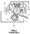
- the toner image is transferred to the surface of the sheet P at the image forming portion (not shown), and the sheet P carrying the transferred and unfixed toner image is conveyed along a guide plate 7 from the image forming portion toward the pinching area between the fixing roller 11 and the pressuring roller 12 and is held at the pinching area between the pressuring roller 12 and the fixing roller 11 temperature of which is controlled by the thermistor 13 and the control means, so that the toner image is fixed to the sheet P by heat applied by the fixing roller 11 and pressure applied from the pressing roller 12 while the sheet P is conveyed by the fixing roller 11 and the pressing roller 12.
- the sheet P on which the toner image has been fixed is separated by the separating claw 17 from the circumferential surface of the fixing roller 11 or that of the pressuring roller 12, and is conveyed by the paired conveying rollers 19 toward the sheet discharge portion (not shown).
- the separating claw 17 and the thermistor 13 are provided respectively as separate component members around the fixing means (that is, the fixing roller 11 in FIG. 6) in the above described conventional fixing device 10, the number of the component parts of the conventional fixing device 10 is large thereby requiring lots of time for assembling the component parts of the large number. Further, members for supporting the thermistor 13, such as the holder 14 and the elastic sponge 15, are also required as separate component parts. This makes the structure and manufacturing cost of the conventional fixing device 10 being complex and high.
- the heat source is provided in the inside of the moving member to apply the heat energy to the moving member
- the moving member is a fixing roller
- the pressing member is structured by a pressing roller contacted with the fixing roller and rotated by the fixing roller.
- the separating means is so arranged as to correspond to a substantial center position of a sheet having the smallest width among sheets used in the image forming apparatus, in a width direction perpendicular to the conveying direction of the sheet in the fixing device.
- the separating means is a leaf spring, and supporting means is further provided which supports one end of the leaf spring and makes a free end of the leaf spring contact the outer surface of the fixing means.
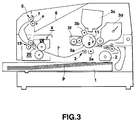
- the fixing device 4 is incorporated in the image forming apparatus (here, a printing apparatus).
- This image forming apparatus comprises: a sheet supply cassette 1 for storing sheets P in a stacked way; a sheet supply roller 2 for supplying the sheets P one by one from the sheet supply cassette 1; an image forming portion 3 for forming a toner image on the sheet P which is supplied from the sheet supply roller 2, on the basis of image information supplied to the image forming portion 3; a guide plate 7 for guiding the movement of the sheet P discharged from the image forming portion 3 after the toner image has been formed on the sheet P; a fixing device 4 provided on an extending end of the guide plate 7, for fixing the toner image to the sheet P; a pair of discharge rollers 5 for discharging the sheet P on which the toner image has been fixed, out of the image forming apparatus (one of the discharge rollers 5 being rotated in a direction of an arrow e and the other in a direction of an arrow f in FIG
- the image forming portion 3 includes a photosensitive drum 3a rotated in a direction of an arrow g, and a charger 3b, an optical write head 3c, a developing unit 3d, a transfer unit 3e, a cleaner 3f, etc., all of which are sequentially arranged around the photosensitive drum 3a in a rotational direction of the photosensitive drum 3a.
- the fixing device 4 includes a fixing roller 11 having a heat source 11a, such as a halogen lamp, arranged inside thereof, and having a surface heated by heat energy produced from the heat source 11a and the fixing roller 11 serving as a moving member, and a pressing roller 12 formed of an elastic roller, such as a silicon rubber roller pressed on the fixing roller 11 with a predetermined pressure force and the pressing roller 12 serving as a pressing member. Further, the fixing device 4 includes a cleaner 18a held by a cleaner holder 18 and removing a matter deposited on the circumferential surface of the fixing roller 11. Such structure of the fixing device 4 as described above is the same as that of the conventional fixing apparatus 10 as shown in FIG. 6.
- the film thermistor member 20 is provided to make its one end contact the circumferential surface of the fixing roller 11 at a sheet exit-side of the pinching area between the fixing roller 11 and the pressing roller 12, and serves both as a separating claw acting as a separating means and as a thermistor acting as a temperature detection element.
- the film thermistor member 20 is so arranged as to correspond to a substantial center position of a sheet p having the smallest width among sheets used in the image forming apparatus, in a width direction perpendicular to the conveying direction of the sheet in the fixing device 4.
- the fixing device 4 of this embodiment In the image forming apparatus in which the fixing device 4 of this embodiment is incorporated, sheets having different widths are so supplied and conveyed with their centers being arranged on one line.
- the fixing device 4 of the present invention can of course be applied to an image forming apparatus in which sheets P having various widths are supplied and conveyed with one of side edge of each of the sheets P being arranged on one line.
- the film thermistor member 20 are so arranged as to correspond to a substantial center position of a sheet p having the smallest width among sheets used in the image forming apparatus, in the width direction of the sheet P.
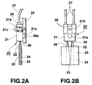
- the film thermistor member 20 has a leaf spring 22 supported at its one end portion by a holder 21 made of a heat resistant-resin and serving as support means, and a bead-like thermistor 23 provided at a free end of the leaf spring 22 and serving as a temperature detecting element.
- the leaf spring 22 is made of such as a thin stainless steel sheet having a thickness of about 100 ⁇ m to 200 ⁇ m. Both the thermistor 23 and the leaf spring 22 are sandwiched between a polyimide tape 24 and a terefluoroethylene tape 25.
- the polyimide tape 24 having heat-resistant nature is arranged on a side on which it directly contact the thermistor 23, and the surface of the polyimide tape 24 provides a heat-sensitive surface which contacts the circumferential surface of the fixing roller 11.
- the thermistor 23 is electrically connected to control means 8 (FIG. 1) through a conductive line 26 extending from the surface of the leaf spring 22 into the interior of the holder 21 and a conductive line 27 extending from the conductive line 26 toward an outside of the holder 21, a connecting portion between the conductive line 26 and the conductive line 27 is covered with a silicone rubber 28.
- the holder 21 is fixed to a top cover 29 of the fixing device 4, and the leaf spring 22 presses its free end on which the thermistor 23 is arranged, through the polyimide tape 24 with a proper pressure on the circumferential surface of the fixing roller 11 at the exit side of the pinching area between the fixing roller 11 and the pressing roller 12.
- the fixing of the holder 21 to the top cover 29 is achieved by, as shown in FIGS. 2A and 2B, engaging an engaging pin 21a projected from the holder 21 into a hole 29a formed in the top cover 29, and by tightening a screw 21c inserted into a hole 21b formed in the holder 21 and screwed into the top cover 29.
- the leaf spring 22 functions as separating means for separating the sheet on which the toner image has been fixed, from the fixing roller 11, and the thermistor 23 functions as a temperature detection element.
- the control means 8 controls the surface temperature of the fixing roller 11 through the heat source 11a on the basis of the detection by the thermistor 23 so as to set the surface temperature to a predetermined temperature level (for example, about 160°C to 180°C).
- the film thermistor member 20 can fully achieve its sheet separating function because it is so arranged as to correspond to the substantial center position of the sheet having the smallest width among sheets used in the image forming apparatus, in the width direction perpendicular to the conveying direction of the sheet.
- the minimal condition under which the film thermistor member 20 exhibits its separating function is that the leaf spring 22 of the film thermistor member 20 can contact the sheet conveyed in the image fixing apparatus at any position in the width direction of the sheet.
- the film thermistor member 20 is comprised of a simple component part, functions both as the separating means (leaf spring 22) and the temperature detection element (thermistor 23), and further is not necessary to provide any independent members for supporting the thermistor 23 (that is, those members, such as the holder 14 and the elastic sponge 15 as shown in FIG. 6). Since the separating means is pressed on the fixing roller 11 with an elastic force of the leaf spring 22, there is no need to provide any extra urging member, such as the separating claw 17 as shown in FIG. 6. This requires less component parts than a conventional fixing device. It is, therefore, possible to assemble a whole of the device at lower cost in a shorter period of time in comparison with the conventional fixing device. Further, the structure of the film thermistor member 20 can be made lower in cost than a conventional combined structure of the thermistor 13 and supporting members 14, 15.
- the separation of the sheet P from the fixing roller 11 is achieved by the film thermistor member 20 only, but an extra separation assisting means may be used together with the film thermistor member 20 of FIG. 1 to more ensure separation of the sheet P from the fixing roller 11.
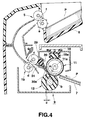
- FIG. 4 is a longitudinal cross-sectional view showing a fixing device according to another embodiment and its neighborhood, the fixing device and the neighborhood being incorporated into an image forming apparatus with the separation assisting means mounted therein.
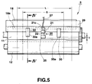
- FIG. 5 is a front view showing the fixing device of FIG. 4 from a downstream side in a sheet conveying direction. In FIG. 5, positional relationship between the film thermistor member 20 and a pair of claw members 30 which serving as the separation assisting means.
- FIG. 4 is a cross-sectional view as taken along line IV-IV in FIG. 5.
- claw members 30 each of which is a normal molding member are arranged at a plurality of places (preferably on both sides of the film thermistor member 20 in FIG. 5) different from the place in which the film thermistor member 20 is arranged, in a longitudinal direction of the top cover 29, that is, in an axial direction of the fixing roller 11 and the pressing roller 12.
- These claw members 30 assist the separation of the sheet P from the fixing roller 11 by the leaf spring 22 of the thermistor member 20 serving as the separation means.
- claw members 30 are different from the conventional separation claw 17 shown in FIG. 6, and forward ends 30a of the claw members 30 are spaced by a small distance d ( ⁇ 0) away from the circumferential surface of the fixing roller 11. Further, as shown in FIG. 5, the forward ends 30a of the claw members 30 are arranged at places spaced by a distance T ( ⁇ 0) from the free end (that is, contacting portion to the fixing roller 11) of the film thermistor member 20 in the down stream side in the rotational direction of the fixing roller 11.
- these claw members 30 are so arranged on both sides of the film thermistor member 20 as to be situated preferably in a region corresponding to the smallest width S of a sheet among the sheets used in the image forming apparatus.
- "L” shows a maximum width of a sheet among the sheets used in the image forming apparatus.
- claw members 30 separate surely both the sides of the sheet to which it is hard to affect the separating function of the film thermistor member 20, so that the sheet can be prevented from being conveyed along with the fixing roller 11 with both side portions of the sheet sticking to the fixing roller 11.
- the sheet on the surface of which a toner image has been formed but not unfixed by the image forming portion 3 is pinched between the fixing roller 11 (the temperature of the fixing roller 11 is controlled on a basis of a temperature detection by the thermistor 23 at the free end of the leaf spring 22) and the pressing roller 12, and is conveyed so that the toner image on the sheet is heated and is fixed on the sheet.
- the sheet on which the toner image has been fixed is separated surely from the circumferential surface of the fixing roller 11 by the leaf spring 22 serving as the separation means and by the claw members 30 serving as the separation assisting means, and then is conveyed by the paired conveying rollers 19 toward the sheet discharge tray 6.
- each of the claw members 30 serving as the separation assisting means to ensure the sheet separating function has substantially the same shape as that of the conventional separating claw 17 in FIG. 6, but the claw members 30 are not in direct contact with the fixing roller 11 as described above. Therefore, the claw member 30 does not need to employ an expensive high temperature-resistant material used for the conventional separation claw 17. Since an inexpensive molding material can be used for the claw members 30, the manufacturing cost of the claw members 30 can be lowered by that extent. Since the number of the claw members 30 to be fixed on the top cover 29 is determined to 2 to 4 in accordance with the size, etc., of a sheet used in the image forming apparatus, assembly of the separation assisting means can be readily achieved for a short period of time.
- the claw member 30 as an independent member is used as the separation assisting means, but the top cover 29 or the guide plate 31 can be used as the separation assisting means by extending its forward end toward a position near to the circumferential surface of the fixing roller 11.
- the cleaner 18 is used for removing matter deposited on the circumferential surface of the fixing roller 11 after the toner image has been transferred from the circumferential surface of the fixing roller 11 to the sheet P, and the paired conveying rollers 19 are used for assisting conveyance of the sheet from the fixing roller 11 toward the sheet discharge tray 6, but these cleaner 18 and paired conveying rollers 19 can be omitted.
- the fixing means including a combination of the fixing roller 11 with the pressing roll 12, but the combination of the moving member having the circlically movable surface with the pressing member is not restricted to a pair of rollers.
- the moving member can be so structured as to wind an endless belt on a plurality of rollers, and the pressing member can be structured by a fixed type guide.
- the heat source 11a is provided in the inside of the moving member (fixing roller 11), but the heat source 11a may be provided on an outside of the moving member or either an inside or an outside of the pressing member.
- the separating means may be provided not only on the moving member side but also on the pressing member side.
- the above described structure of the film thermistor member 20 is one example and is not restricted thereto. Any other structures can be used so long as the separating means is equipped with a temperature detection element at the contacting portion which contact the fixing means and can perform both the separating function and the temperature detection function.
- the separating means and temperature detection element are incorporated in one member and it is not necessary to provide any independent member for supporting the temperature detection element. It is, therefore, the number of the component parts can be reduced so that the assembling time and the manufacturing cast of the whole of the image forming apparatus can be reduced.
Landscapes
- Physics & Mathematics (AREA)
- General Physics & Mathematics (AREA)
- Fixing For Electrophotography (AREA)
Applications Claiming Priority (2)
| Application Number | Priority Date | Filing Date | Title |
|---|---|---|---|
| JP6621594 | 1994-04-04 | ||
| JP66215/94 | 1994-04-04 |
Publications (1)
| Publication Number | Publication Date |
|---|---|
| EP0676677A2 true EP0676677A2 (de) | 1995-10-11 |
Family
ID=13309389
Family Applications (1)
| Application Number | Title | Priority Date | Filing Date |
|---|---|---|---|
| EP19950104966 Withdrawn EP0676677A2 (de) | 1994-04-04 | 1995-04-03 | Fixiervorrichtung ausgestattet mit einer Trennvorrichtung mit Blattrennungsfunktion und Fixiertemperatur-Detektierungsfunktion |
Country Status (1)
| Country | Link |
|---|---|
| EP (1) | EP0676677A2 (de) |
Cited By (2)
| Publication number | Priority date | Publication date | Assignee | Title |
|---|---|---|---|---|
| WO1999004318A1 (en) * | 1997-07-17 | 1999-01-28 | Minnesota Mining And Manufacturing Company | Film removal mechanism for use with a thermal drum processor system |
| EP1569046A1 (de) * | 2004-02-27 | 2005-08-31 | Canon Kabushiki Kaisha | Bilderzeuungsgerät mit einer Detektoreinheit zur Messung der Temperatur eines Aufzeihnungsmediums |
-
1995
- 1995-04-03 EP EP19950104966 patent/EP0676677A2/de not_active Withdrawn
Cited By (4)
| Publication number | Priority date | Publication date | Assignee | Title |
|---|---|---|---|---|
| WO1999004318A1 (en) * | 1997-07-17 | 1999-01-28 | Minnesota Mining And Manufacturing Company | Film removal mechanism for use with a thermal drum processor system |
| US6091480A (en) * | 1997-07-17 | 2000-07-18 | 3M Innovative Properties Company | Film removal mechanism for use with a thermal drum processor system |
| EP1569046A1 (de) * | 2004-02-27 | 2005-08-31 | Canon Kabushiki Kaisha | Bilderzeuungsgerät mit einer Detektoreinheit zur Messung der Temperatur eines Aufzeihnungsmediums |
| US7280775B2 (en) | 2004-02-27 | 2007-10-09 | Canon Kabushiki Kaisha | Image-forming apparatus and recording-medium-temperature detector unit used in the same |
Similar Documents
| Publication | Publication Date | Title |
|---|---|---|
| JP2940161B2 (ja) | 像加熱装置 | |
| JP2884714B2 (ja) | 像加熱装置 | |
| JP2900604B2 (ja) | 像加熱装置 | |
| US4965640A (en) | Image forming apparatus including detachable toner fixing unit | |
| JP2884717B2 (ja) | 像加熱装置 | |
| JP2861280B2 (ja) | 加熱装置 | |
| JP2926904B2 (ja) | 像加熱装置 | |
| JP2884718B2 (ja) | 像加熱装置 | |
| CN100442162C (zh) | 像加热装置 | |
| US5852763A (en) | Image heating apparatus | |
| JPH04204983A (ja) | 加熱装置 | |
| US20010032835A1 (en) | Image heating apparatus, heater for heating image and manufacturing method thereof | |
| EP0494627A2 (de) | Heizvorrichtung mit abgestuftem Teil und Heizgerät hiermit | |
| JPH04204981A (ja) | 加熱装置 | |
| EP0441402B1 (de) | Bildfixiergerät ohne Verknittern des Fixierbandes | |
| JPH08115003A (ja) | トナー画像の加熱定着装置 | |
| EP0676677A2 (de) | Fixiervorrichtung ausgestattet mit einer Trennvorrichtung mit Blattrennungsfunktion und Fixiertemperatur-Detektierungsfunktion | |
| US5811759A (en) | Fixing device | |
| US4870464A (en) | Separating/guiding device for an electronic copying machine | |
| JP2987965B2 (ja) | 像加熱装置 | |
| JPH03226985A (ja) | 定着装置 | |
| JP2958039B2 (ja) | ヒートロール定着装置のジャム防止機構 | |
| JP2000275992A (ja) | 画像形成装置 | |
| JP2626564B2 (ja) | 熱定着装置 | |
| JP2949878B2 (ja) | 加熱装置 |
Legal Events
| Date | Code | Title | Description |
|---|---|---|---|
| PUAI | Public reference made under article 153(3) epc to a published international application that has entered the european phase |
Free format text: ORIGINAL CODE: 0009012 |
|
| 17P | Request for examination filed |
Effective date: 19950403 |
|
| AK | Designated contracting states |
Kind code of ref document: A2 Designated state(s): DE FR GB |
|
| STAA | Information on the status of an ep patent application or granted ep patent |
Free format text: STATUS: THE APPLICATION HAS BEEN WITHDRAWN |
|
| 18W | Application withdrawn |
Withdrawal date: 19951010 |