EP0676703A2 - Eine Technik zum Erreichen eines blockierungsfreien Durchschaltens eines Mehrstufen-Koppelpunkt-Packetschalters - Google Patents
Eine Technik zum Erreichen eines blockierungsfreien Durchschaltens eines Mehrstufen-Koppelpunkt-Packetschalters Download PDFInfo
- Publication number
- EP0676703A2 EP0676703A2 EP95100957A EP95100957A EP0676703A2 EP 0676703 A2 EP0676703 A2 EP 0676703A2 EP 95100957 A EP95100957 A EP 95100957A EP 95100957 A EP95100957 A EP 95100957A EP 0676703 A2 EP0676703 A2 EP 0676703A2
- Authority
- EP
- European Patent Office
- Prior art keywords
- route
- network
- packet
- routes
- nodes
- Prior art date
- Legal status (The legal status is an assumption and is not a legal conclusion. Google has not performed a legal analysis and makes no representation as to the accuracy of the status listed.)
- Granted
Links
- 238000000034 method Methods 0.000 title claims abstract description 43
- 238000012545 processing Methods 0.000 claims abstract description 152
- 238000005192 partition Methods 0.000 claims abstract description 37
- 230000004044 response Effects 0.000 claims description 4
- 238000004891 communication Methods 0.000 description 11
- 230000005540 biological transmission Effects 0.000 description 9
- 239000011159 matrix material Substances 0.000 description 8
- 230000009467 reduction Effects 0.000 description 6
- 230000006870 function Effects 0.000 description 5
- 230000002441 reversible effect Effects 0.000 description 5
- 230000015572 biosynthetic process Effects 0.000 description 3
- 230000000903 blocking effect Effects 0.000 description 3
- 230000003993 interaction Effects 0.000 description 3
- 238000012423 maintenance Methods 0.000 description 3
- 238000012546 transfer Methods 0.000 description 3
- 230000008859 change Effects 0.000 description 2
- 238000010586 diagram Methods 0.000 description 2
- 239000004744 fabric Substances 0.000 description 2
- 238000002955 isolation Methods 0.000 description 2
- 230000008569 process Effects 0.000 description 2
- 230000002829 reductive effect Effects 0.000 description 2
- 238000000638 solvent extraction Methods 0.000 description 2
- 230000002411 adverse Effects 0.000 description 1
- 238000004458 analytical method Methods 0.000 description 1
- 230000003466 anti-cipated effect Effects 0.000 description 1
- 230000009118 appropriate response Effects 0.000 description 1
- 239000000872 buffer Substances 0.000 description 1
- 230000015556 catabolic process Effects 0.000 description 1
- 239000000470 constituent Substances 0.000 description 1
- 230000007812 deficiency Effects 0.000 description 1
- 238000006731 degradation reaction Methods 0.000 description 1
- 238000010348 incorporation Methods 0.000 description 1
- 230000002401 inhibitory effect Effects 0.000 description 1
- 230000001788 irregular Effects 0.000 description 1
- 230000008520 organization Effects 0.000 description 1
- 230000000135 prohibitive effect Effects 0.000 description 1
- 238000004088 simulation Methods 0.000 description 1
- 238000001228 spectrum Methods 0.000 description 1
- 238000012916 structural analysis Methods 0.000 description 1
- 230000001360 synchronised effect Effects 0.000 description 1
- 238000012360 testing method Methods 0.000 description 1
- 238000009827 uniform distribution Methods 0.000 description 1
Images



Classifications
-
- H—ELECTRICITY
- H04—ELECTRIC COMMUNICATION TECHNIQUE
- H04L—TRANSMISSION OF DIGITAL INFORMATION, e.g. TELEGRAPHIC COMMUNICATION
- H04L45/00—Routing or path finding of packets in data switching networks
Definitions
- the invention relates to apparatus and an accompanying method for establishing deadlock-free routing in a multi-stage inter-connected cross-point based packet switch.
- This invention is particularly, though not exclusively, suited for incorporation within a high speed packet network used within a massively parallel processing system.
- each processing element typically contains a separate microprocessor and its associated support circuitry, the latter being typified by, inter alia, random access memory (RAM) and read only memory (ROM), for temporary and permanent storage, respectively, and input/output (I/O) circuitry.
- each processing element also contains a communication sub-system, formed of an appropriate communications interface and other hardware as well as controlling software, that collectively serves to interface that element to the packet network.
- the overall performance of a massively parallel processing system is heavily constrained by the performance of the underlying packet network used therein.
- the packet network is too slow and particularly to the point of adversely affecting overall system throughput, the resulting degradation may sharply and disadvantageously reduce the attractiveness of using a massively parallel processing system in a given application.
- each processing element executes a pre-defined granular portion of an application.
- each element In executing its corresponding application portion, each element generally requires data from, e.g., an application portion executing on a different element and supplies resulting processed data to, e.g., another application portion executing on yet another processing element.
- each processing element Owing to the interdependent nature of the processing among all the elements, each processing element must be able to transfer data to another such element as required by the application portions then executing at each of these elements.
- the processing element i.e. a "destination" element, requests data from another such element, i.e.
- the destination element remains idle, at least for this particular application portion, until that element receives a packet(s) containing the needed data transmitted by the source element, at which point the destination element once again commences processing this application portion.
- a finite amount of time is required to transport, through the packet network, a packet containing the request from the destination to the source processing elements and, in an opposite direction, a responding packet(s) containing the requested data.
- This time unavoidably injects a degree of latency into that application portion executing at the destination element. Since most processing elements in the system function as destination elements for application portions executing at corresponding source elements, then, if this communication induced latency is too long, system throughput may noticeably diminish.
- the packet network needs to transport each packet between any two communicating processing elements as quickly as possible in order to reduce this latency.
- the network must be able to simultaneously route a relatively large number, i.e. an anticipated peak load, of packets among the processing elements.
- each switch typically being an 8-port bi-directional router in which all the ports are internally inter-connected through a cross-point matrix.
- each switch in one stage beginning at one (i.e. a so-called "input") side of the network, is inter-connected, through a unique corresponding path (typically a byte-wide physical connection), to a switch in the next succeeding stage, and so forth until the last stage is reached at an opposite (i.e. a so-called "output") side of the network.
- switch chip a relatively inexpensive single integrated circuit
- switch chip that, operationally speaking, is non-blocking
- use of these switch chips is favored.
- switch chip implemented as a non-blocking 8-way router, that relies on use of a central queue
- serial number 08/027,906 filed March 4, 1993 and which is incorporated by reference herein (and which is commonly assigned to the present assignee hereof).
- Inter-switch chip routes are typically pre-defined, during system initialization, in a manner that attempts to balance traffic flow throughout the entire network such that, over a relatively short time, each byte-wise path will carry an approximately equal number of packets. Once these routes are set and other than a switch chip or path failure or maintenance condition, the routes rarely, if ever, change.
- the assigned routes available to each processing element are then supplied to that element, again during system initialization, in the form of a (local) route table. Subsequently, during routine operation, as each processing element forms a packet, that element, based upon the destination of this packet, reads the route from its route table and simply inserts the route as values of appropriate route bytes in a header of the packet.
- the packet is then launched into the network and routed through successive switch chips (and switching stages) as specified by the value of corresponding route bytes in the packet.
- a switching stage i.e. here passes through two switch chips in the same stage
- the last switch chip in the stage truncates the corresponding route byte from the packet header.
- a routing deadlock can occur whenever corresponding packets, each situated in, e.g., the central queue within a group of different switch chips, are waiting to be simultaneously routed over common paths that connect pairs of switch chips in successive stages.
- each of these switch chips essentially waits for the others in the group to route their packets over these particular paths. Because none of the packets for this group is able to transit through its associated central queue until any one of the packets for this group is routed, all these packets simply wait and the corresponding paths become deadlocked with no resulting traffic flow thereover.
- the processing elements, to which these packets are destined also continue to wait for these packets which, in turn, halts their processing throughput. Consequently, the bandwidth of the network skews to favor only those remaining processing elements unaffected by the deadlock which, in turn, can severely imbalance the processing workload and significantly diminish system throughput.
- this technique is costly. Nevertheless, the additional cost of duplicating one switch board and associated circuitry is tolerable in a 32-processor system. As such, this technique is used to avoid deadlocks in a 32-processor system. In fact, a sufficient potential for deadlocks exists in a 32-processor system to rule out forming the packet network with only one switch board. However, this cost penalty simply becomes prohibitive for use in larger systems, such as a 512-processor system, where sixteen additional switch boards would be needed above the sixteen minimally required in the network.
- this technique Since the technique of prohibiting routes merely requires selecting certain entries to include in the route table for each processing element, this technique is very simple and highly cost-effective to implement. Thus, this technique would be readily favored for inclusion in a multi-stage cross-point packet network but for its inability to create a symmetric bandwidth reduction across the entire network.
- our present invention provides a simple, cost-effective technique, that advantageously overcomes the deficiencies inherent in the art, for preventing routing deadlocks from occurring in large scale bi-directional multi-stage inter-connected cross-point switch based packet networks.
- Our technique is ideally, though not exclusively, suited for use within such a packet network that forms the communications backbone of a large scale massively parallel processing system.
- routes would be prohibited from being considered, during the formation of the route tables, based upon a relative location of the particular nodes in the network, e.g. processing elements, that would otherwise use those routes.
- the prohibited routes are selected as those which, if not used, would prevent closed loop routing patterns and hence routing deadlocks from arising.
- routes are prohibited in order to isolate packet traffic that would flow solely between nodes in one partition, e.g. half, of the system from packet traffic that would flow between nodes in another partition, e.g. the other system half.
- a 512-processor system would be constructed with a number of identical 320 port switch boards, organized into two inter-connected stages: node switch boards (NSB) that connect to the individual processing elements and intermediate switch boards (ISB) that are used to inter-connect the node switch boards themselves.
- NNB node switch boards
- ISB intermediate switch boards
- Each NSB provides 16 ports to connect to each of 16 different processing elements and another 16 ports to inter-connect to a different port on each of the sixteen ISBs.
- route selection can be made, for eventual inclusion within the global route table, among all routes that are then available, without any limitation based upon system half.
- each partition e.g. half
- routing deadlocks that would otherwise arise from interaction of these packets, are advantageously prevented. This, in turn, permits commercializable parallel processing systems to be readily expanded to encompass greater numbers of processing elements and thus serve a wider variety of application processing needs than those heretofore possible.
- packet networks containing bi-directional multi-stage inter-connected cross-point based packet switches are susceptible to routing deadlocks of the type addressed described herein. Therefore, after considering the following description, those individuals will clearly realize that the teachings of our present invention can be easily and highly cost-effectively incorporated into nearly any such packet network to prevent these deadlocks from occurring with only a small ensuing reduction in transmission bandwidth.
- our invention will find ready use in packet networks, of essentially any size, destined for use across a wide and diverse range of packet switching environments, whether they be for digital communications, such as in a public or private telephone (e.g.
- FIG. 1 This system contains 32-node packet switch (also referred to herein as "packet network” or simply “network") 100 to which 32 separate, though generally identical, processing elements 110, specifically processing elements 1100, 1101, ..., 11031, are connected to each of 32 nodes, correspondingly numbered from 0 to 31 provided by this network. Each element forms a processing node of the system.
- the network provides high speed transport of packets from any one of these processing nodes to any other one.
- the processing elements themselves are each microprocessor based, typically using an RS6000 RISC microprocessor manufactured by the IBM Corporation.
- network 100 is configured using eight separate 8-by-8 bi-directional switch circuits 120 organized into two inter-connected stages: an "input” stage containing four switch circuits 1200, 1201, 1202 and 1203 and an "output” stage containing four switch circuits 1204, 1205, 1206 and 1207.
- the designation "input” and “output” are purely arbitrary for purposes of discussion; in actuality, any stage or port on the network can serve as either an input or output stage or port.
- Each of these switch circuits is preferably a central queue based non-blocking 8-way router, particularly that described in co-pending United States patent application entitled: "A Central Shared Queue Based Time Multiplexed Packet Switch with Deadlock Avoidance" by P.
- each of the switch chips contains a central queue, illustratively queues 1300, 1301, 1302, ..., 1307 situated within corresponding switch circuits 1200, 1201, 1202, ..., 1207.
- the purpose of each central queue is to provide an alternate route through the corresponding switch circuit to, inter alia, ameliorate input blockage and deadlocks, the latter being caused by input ports (specifically the FIFO buffers therein) and queues filled with opposing traffic -- a different form of deadlock than that to which the present invention is directed.
- connection matrix 140 The input and output stages of the network are inter-connected through connection matrix 140, with each of these connections being essentially a byte-wide physical link (cable), of which illustrative links 1400, 1401, 1402 and 1403 are specifically numbered.
- a port on each one of the switch chips in the input stage is separately and physically connected to a corresponding port of every one of the switch chips in the output stage.
- switch chip 1200 which provides ports 0-7, is connected through its ports 4, 5, 6 and 7, via corresponding cables, to port 4 on each of switch chips 1204, 1205, 1206 and 1207 all in the output stage.
- Packet switch 100 containing the eight switch chips and connection matrix 140, collectively comprise a single switch board. Ports 0-3 of each switch chip are connected to links external to the switch board; while ports 4-7 of each such chip are connected to links (cables) within connection matrix 140 and hence, therethrough, to a port of another such switch chip within the same board.
- a "source” processing element based on an application portion it is executing, fabricates a packet containing an appropriate message, with either instructions and/or data, and transmits that packet into packet switch 100 for transport to a "destination" processing element.
- the destination element then processes the data and/or instructions contained in the packet and produces an appropriate response which, in turn, based on the application portion executing at the destination processing element, is fabricated into another packet and, e.g., transmitted back into the network for transport to either the source or a different processing element for further processing, and so forth.
- each packet contains a header with specific routing instructions in the form of route bytes. As described below, all routes are pre-defined. Once a source processing element determines the destination for a given packet it is assembling, that element merely accesses its internal (local) route table, with the destination processing element as an address, and reads the route thereto in the form of values of the appropriate route bytes. These values are simply inserted, as the route bytes, into the header of the packet.
- FIG. 2 shows the organization of a typical packet, i.e. packet 200, which is transported through the packet network. Individual packets may be as long as 255 bytes.
- packet 200 contains a succession of fields: length field 210; route field 220 which itself contains route bytes 2201, 2202, ..., 220 n ; sequence number field 230; and data field 240 length field 210 contains an 8-bit volume which specifies the length of the packet in bytes.
- Route field 220 contains several bytes, specifically route bytes 2201, 2202, .., 220 n , which collectively specify a particular and singular route (path) which the packet is to follow through the entire network from its source node to its destination node.
- Field 230 holds a sequence number provided by the source processing element. This number, assigned by the source processing element for this packet and used by the destination processing element, identifies the order of the packet in a given sequence. As such, this number can be used as a check to prevent destination processing of out-of-sequence packets.
- Data field 240 contains a succession of bytes that collectively form the data (which may contain actual data and/or instructions) being carried by the packet to a destination processing node. Fields 210, 220 and 230 collectively form a packet header.
- the number (n) of route bytes that appears within routing field 220 is determined by the number of switching stages through which the packet will transit. In that regard, each route byte holds routing instructions for two successive switch chips. Hence, if the packet is only to transit through two switch chips in two successive stages, such as shown in FIG. 1, in the network to reach the destination processing node, field 220 only contains route byte 2201, and so forth, in a layer network, for additional pair of switch chips used therein. All the route bytes have the same format.
- a route byte (R[7:0]) consists of a 1-bit field selector (R[7] -- not specifically shown) and two 3-bit route fields (R[6:4] and R[2:0] -- both of which are also not specifically shown). If the value of bit R[7] is zero, then a switch chip routes the packet to an output port on that chip specified by the binary value of bits R[6:4] and then sets the value of bit R[7] to one. Alternatively, if the value of bit R[7] is one, then the switch chip routes the packet to the output port on that chip specified in bits R[2:0] and, while doing so, discards this entire route byte; thus parsing the route byte from the packet. Hence, each route byte provides routing instructions for two successive switch chips. By concatenating n route bytes into route field 220, each packet can be routed through up to 2n stages of switch chips.
- a switch chip that receives a packet examines the first route byte then existing in that packet and routes the packet to the port indicated by that byte. In the course of doing so, every alternate switch chip in the path of the packet truncates (removes) that entire route byte from the packet. This, in turn, makes the next successive route byte in route field 220 the first route byte for the next switch chip and switching stage. Upon arriving at the destination processing node, the packet will contain no route bytes. Each switch chip is oblivious to any additional route bytes beyond the first byte then carried by the packet and upon which that circuit conducts its specific routing. Furthermore, each switch chip does not distinguish between any route bytes other the first route byte and any following data bytes.
- routing is accomplished, during packet assembly, by first inserting pre-defined route bytes into a packet header with subsequently actual routing of the packet being conducted and dictated, within the network independent of the source and destination processing elements, by the specific value of each of those bytes.
- FIG. 3 depicts processing nodes 110 that comprise system 5, shown in FIG. 1, and specifically the various files and tables resident in memory within these nodes to accomplish packet routing.
- Packet switch (network) 100 functions in two modes, time multiplexed together: a run phase, during which the switch circuits simply route incoming packets, and a service phase, during which the processors are initialized and/or the network is monitored and managed on a circuit-switched basis. All devices attached to the network transfer between modes on a synchronized lock-step basis. During the run phase, certain processing elements may be relegated to certain tasks.
- processing elements 1100 and 1101 may be dedicated as input/output (I/O) nodes in order to provide links from system 5 to other networks or processing systems and thus transfer information therebetween.
- Other processing elements such as illustratively elements 1102, 1103, ..., 11031 may all be used as compute nodes for actual application processing.
- One of the processing elements, such as processing element 11031 is used as a service processor to undertake various network operations during the service phase. If desired, during the run phase, the service processor can also function as a compute node. Though the service processor is identical, from a hardware standpoint, with all the other processing elements, the service processor contains, within its memory (here memory 340), and executes additional software, inter alia initialization routines 370, that execute during the service phase.
- this phase provides: initialization, communication link synchronization, global time synchronization, fault determination and isolation and various diagnostic services to all the switch circuits and all other devices, including all other processing elements, connected to the network. Since the initialization function is the only portion of the service phase relevant here, only this portion of the service phase will be discussed hereinbelow and particularly only those aspects pertinent to packet routing and our present invention. The initialization phase is undertaken before the system undertakes any application processing.
- Service processor 11031 stores, within its memory 340, a database, specifically topology file 350, of structured entries that collectively define each and every device, including (though not limited to) all the processing elements, that are connected to the network and the specific bi-directional physical connections (cables) used in the network to link these devices.
- topology file the maximum numbers of switch circuits and other devices are identified first, by a device entry, followed thereafter by an entry of each physical connection that exists between any of these circuits and the devices.
- a device entry contains two numeric fields and is of the form: "number of devices (n v ); number of switch circuits (n s )".
- device identification (id) numbering is then assumed to be in the range from 0 to n v and switch circuit id numbering from 0 to n s .
- the device entry would simply be "16 8".
- Each connection entry has six fields and is the form of: "device 1-type; device 1-id; device 1-port; device 2-type; device 2-id; device 2-port”.
- Device-type information specifies the nature of the device, i.e. whether that device is a processing element, if so, whether that element is the service processor, or whether that element is a switch circuit.
- connection entry might be "tb0 14 0 s 3 6" which indicates that "a processing element labeled with id 14 is connected in full-duplex fashion from its port 0 to both input and output port 6 on switch circuit 3".
- the wiring of the network is usually quite regular, well defined and symmetric. However, in actuality, some of the switch boards may be powered down for maintenance or other network components, such as cables, switch circuits (specifically the switch chips used therein) or processing elements, intentionally isolated as a result of a failure condition. Hence, the resulting network topology at any one time may be quite irregular.
- service processor 11031 reads topology file 350, as it then exists, and then physically determines, through broadcasting test messages and receiving corresponding responses thereto, the status of each connection in the network as well as of each device connected thereto. Based upon these responses, the service processor determines, using, e.g., a well-known breadth-first search, all the available routes that can be used to connect each (source) node of the network to every other (destination) node of the network. Given the path redundancies inherent in the bi-directional multi-stage cross-point network, several routes, through different switch circuits in different switch stages, often exist to connect a pair of source and destination nodes.
- the service processor selects one of these routes for each of these pairs of nodes and stores that route in global route table 360 within memory 340.
- These routes are selected primarily on a shortest-path basis consistent with achieving, over a unit time, a substantially uniform distribution of packet traffic throughout the network in order to avoid traffic congestion and hot-spots in the network.
- service processor 11031 then provides, through the network, a corresponding portion of that table to each of the individual processing elements, including itself, for storage thereat as a local route table. That portion contains only those routes which list that particular processing element as the source node.
- processing element 1100 stores, within its memory 310, local route table 320; and service processor 11031 stores, within its memory 340, local route table 380, and so forth for each of the other processing elements.
- each processing element merely accesses its local route table, and, based upon the destination of the packet then being assembled, copies the values of the routing bytes for that destination from the table into the header for that packet.
- a routing deadlock can occur whenever corresponding packets, each situated in, e.g., the central queue within different switching stages of switch chips, are waiting to be simultaneously routed over common paths that connect pairs of switch chips in successive stages. Therefore, assume, for the moment, that a packet, denoted as "A”, resides in central queue 1300 of switch chip 1200 and is awaiting to be routed from processing node 1100, over a dashed line path identified with a circled "A", to processing node 1104.
- packet "A” would be directed by switch chip 1200, over cable 1400, to port 4 of switch chip 1204, and then be routed back, via port 5 of this latter chip and cable 1401, to the input stage, and specifically port 0 of switch chip 1201 which connects to processing node 1104.
- three other packets labeled “B”, “C” and “D”, reside in central queues 1304, 1301 and 1305 within switch chips 1204, 1201 and 1205, respectively.
- Packet "B” is to be routed from processing element 11017, connected to node 1 of switch chip 1204, via a dashed line path labeled with a circled “B”, to processing element 11023 connected to node 3 of switch chip 1205.
- packet “C” is to be routed from processing element 1106, connected to node 2 of switch chip 1201, via a dashed line path labeled with a circled “C”, to processing element 1102 connected to node 2 of switch chip 1200.
- packet “D” is to be routed from processing element 11021, connected to node 1 of switch chip 1205, via a dashed line path labeled with a circled “D”, to processing element 11016 connected to node 0 of switch chip 1204.
- routes would be prohibited from being considered, during formation of the global route table, based upon a relative location of the particular processing elements (network nodes) that would otherwise use those routes.
- the prohibited routes are selected as those which, if not used, would prevent closed loop routing patterns and hence routing deadlocks from arising.
- routes are prohibited in order to isolate packet traffic that would flow solely between nodes in one partition, e.g. half, of the system from packet traffic that would flow between nodes in another partition, e.g. the other system half.
- the system uses a number of switch boards, each identical to that described above, organized into two inter-connected stages of switch boards: node switch boards (NSB), in one such stage, that connect to the individual processing elements and intermediate switch boards (ISB), in another such stage, that are used to inter-connect the node switch boards.
- NNB node switch boards
- ISB intermediate switch boards
- a 512-processor system typically employs 48 separate switch boards with 32 such boards dedicated as NSBs and 16 remaining boards dedicated as ISBs.
- Each NSB provides 16 ports to connect to each of 16 different processing elements and another 16 ports to inter-connect to a different port on each of the sixteen ISBs.
- the NSBs route packets from and to individual processing elements connected thereto and the ISBs route packets between different NSBs, with all entire route routing specified, as described above, by routing bytes contained in the packet headers.
- FIG. 4 An illustrative 512-processor system is depicted as system 400 in FIG. 4. As shown, this system provides 512 different processing elements 4150, ..., 41515, ... 415496, ... 415511, collectively shown as processing nodes 410 and organized, from a physical standpoint, into 32 physical racks of 16 processing elements each, specifically processing racks 4100, ... 41031. Each rack is, in turn, connected to sixteen ports of a respective NSB.
- System 400 contains 32 NSBs 4400, 4401, 4402, 4403, 4404, 4405, ..., 44030 and 44031 (also designated as NSB 0, NSB 1 and so forth).
- each NSB is inter-connected, through individual cables in connection matrix 450, to a corresponding port on each one of the sixteen ISBs 460, specifically ISBs 4600, 4601, 4602, ..., 46015 (also designated as ISB 0, ISB 1 and so forth).
- each one of sixteen ports on NSB 4400 (NSB 0) is connected to port 0 on a different corresponding one of the sixteen ISBs, such that NSB 4400 can route a packet to each of the ISBs.
- the other NSBs are inter-connected, as shown, in a similar fashion to every one of the ISBs.
- all the switch boards, whether an ISB or an NSB are identical to each other, the ISBs are shown in a manner, different from the NSBs, that facilitates easy depiction of connection matrix 450.
- routing deadlocks can occur, in the absence of using our invention, because a packet, when routed between different NSBs, reverses its direction within an ISB, in much the same fashion as packets "A" and "C” reverse their direction (are “turned around") within switches 1204 and 1205 in system 5 shown in FIG. 1. Since packets do not originate within an ISB, as shown in FIG. 4, but are merely routed therethrough between separate NSBs, closed loop routing patterns, if they were to arise, would of necessity extend to the ISBs and not be limited to exist solely within an NSB. As such, a routing deadlock in system 400 will not be confined to just any one or more of the NSBs themselves.
- system 400 illustratively in half.
- sixteen consecutive NSBs e.g. NSBs 0-15 and NSBs 16-31) and 256 consecutive processing elements e.g. (respectively elements 4150, ..., 415255 and 415256, ..., 415511) would be allocated to each half.
- the first eight ISBs would be in one half; the remaining eight ISBs would be in the other half.
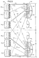
- FIG. 5 shows ISBs 460 along with all the NSBs that comprise system 400 shown in FIG. 4. As shown, the system is partitioned into halves 503 and 507.
- a common port, such as port 0 (not specifically labeled), on each of the 32 NSBs is connected, through a separate corresponding path (cable) to a corresponding one of 32 ports on a single ISB, and so forth for each of the remaining ports on all the NSBs and other ISBs.
- System half 503 encompasses NSBs 4400 through 44015 and ISBs 4600 through 46015.
- NSBs 4400 through 44015 are shown as connected, through paths (cables) 510 0,0 , 510 1,0 , ..., 510 15,0 to sixteen consecutive ports (of which only three are specifically shown) of a single ISB, here ISB 4600 and particularly switch chips 5300 through 5303 therein.
- Remaining system half 507 encompasses NSBs 44017 through 44031 and ISBs 4608 through 46015. Similarly, these particular NSBs are shown as connected through paths 510 16,15 , 510 17,15 , ..., 510 31,15 to corresponding ports of a single ISB, here ISB 46015 and particularly switch chips 5404 through 5407 therein.
- a packet that is to transit between processing elements located within a common half of the system such as half 503
- only those available routes, including ISBs, completely contained within that half of the system would be allowed (such as illustratively route 522 between NSBs 4400 and 44015, and route 524 between NSBs 44031 and 44016); all other routes (such as dashed-line route 534 between NSBs 4400 and 44015 and dashed-line route 532 between NSBs 44031 and 44016) would be prohibited.
- any of the latter routes could not be included, during system initialization, within the global route table to connect these processing elements.
- a prohibited route is also indicated by an "X" through the route.
- route selection can be made, for eventual inclusion within the global route table, among all routes (including one, (not specifically shown) between NSBs 4400 and 44016, that are then available, without any limitation based upon system half.
- Route prohibition is carried out through processing a specific routing directive, as described below, while the global route table is being generated. This processing excludes all prohibited routes from being selected as the defined route between a given pair of network nodes.
- routing deadlock can be advantageously prevented.
- FIG. 6 depicts a high level flowchart of Route Table Generator routine 600 that is executed within a service processor, illustratively processing element 415511, situated within system 400 shown in FIG. 4 in order to define packet routes in accordance with our inventive teachings.
- Routine 600 is part of the initialization routines which, as discussed above, execute within the service processor.
- routine 600 Upon entry into routine 600, as shown in FIG. 6, execution first proceeds to block 610 which, when executed, reads the topology file and the accompanying routing directives.
- an appropriate directive must be included into the topology file for each device in the packet network, e.g. a switch circuit (or specifically a switch chip used therein), indicating whether routing through that device is to be restricted or not, i.e. whether a packet can reverse direction through this circuit.
- a switch board such as that shown in FIG. 1 which embodies network 100.
- ports 0-3 of each switch chip are connected to links external to the switch board; while ports 4-7 of each switch chip are connected to links (cables) within connection matrix 140 and, therethrough, to a port of another switch chip in the same board.
- a routing directive "nr" specified, in the topology file, against a particular switch chip signifies that there are no routing restrictions with respect to that chip. As such, a packet can enter this chip on any of its eight ports and leave the chip on any other port; in this instance, the packet can reverse its direction ("turn around") within the chip.
- n-i-t a routing directive "n-i-t" exists in the topology file against the switch chip, then a packet entering on either ports 4-7 would be constrained to be routed to and exit from chip only on any of ports 0-3; that packet would be prohibited from reversing its direction within the chip.
- an "n-i-t" directive would not restrict packets arriving on any of ports 0-3 of the switch chip, which can be routed to any other port on that chip.
- a sample line in the topology file with a deadlock avoidance directive is: aux routing n-i-t 330 331 332 333 where: "aux routing” signifies an auxiliary line with a routing directive; and "330 331 332 333" are numeric identifiers for certain switch circuits in the format used within the topology file.
- execution proceeds to block 620 which sets the weight associated with each cable (link) specified in the topology file to zero.
- a source node counter, node i is initialized to zero.
- execution passes to block 630.
- This particular block utilizing the data contained in the topology file together with the accompanying deadlock avoidance routing directives, picks a set of available routes, through the packet network, to connect a current source node (node i) with every destination node within the system.
- the routes are chosen, through a well-known breadth-first search, to be those with the shortest lengths, i.e. those having the fewest individual links (cables) and not necessarily those with the shortest physical length.
- a pseudo-code representation of deadlock avoidance route selection is as follows: Selection of the set of shortest-path routes is occurs on a source-based basis, as indicated in block 640, until routes are extended from the current source node to all destination nodes, i.e. when the routes become destination-based. If only one shortest length route results from the source node to a destination node, that route is selected for use therebetween. Alternatively, in those instances, where multiple such routes result between this source node and a common destination node, the one selected route is the one having cables with collectively the lowest weight. Through weight based selection, the traffic load can be balanced, with minimal cable sharing, throughout the entire packet network. Once a particular route is selected between the source node and a destination node, the weight associated with each cable in that route is incremented by one. Though blocks 630 and 640 are shown as distinct blocks to enhance understanding, the operations are generally combined together.
- execution proceeds to block 650 which executes to write all the selected routes into the global route table, thereby forming a route table for the current source node. Thereafter, execution passes to decision block 660 to determine whether a route table has been written, into the global route table, for every node in the network. If route tables have not been written for every node, decision block 660 routes execution, via NO path 667, to block 670. This latter block, when executed, increments source node counter i by one. Execution then loops back, via path 675, to block 630 to determine and write routes for the next successive node, and so forth.
- routine 600 if route tables have been written for all the nodes, then execution exits from routine 600, via YES path 663, emanating from decision block 660. Subsequent to the execution of this routine and prior to the completion of initialization process, the service processor, as discussed above, will provide (specifically copy), through the network, a corresponding portion of the global route table to each and every one of the individual processing elements, including itself, for storage and subsequent use thereat as a local route table. That portion contains only those selected routes for which that particular processing element is a source node.
- our invention can be applied to eliminate routing deadlocks in substantially any size parallel processing system that utilizes a bi-directional multi-stage inter-connected cross-point based packet network.
- our invention can be readily incorporated into a 64-processor system, a 256-processor system and similar systems of other sizes, as well as in other systems that utilize multi-stage inter-connected cross-point packet networks regardless of their end use.
Landscapes
- Engineering & Computer Science (AREA)
- Computer Networks & Wireless Communication (AREA)
- Signal Processing (AREA)
- Data Exchanges In Wide-Area Networks (AREA)
- Multi Processors (AREA)
Applications Claiming Priority (2)
| Application Number | Priority Date | Filing Date | Title |
|---|---|---|---|
| US222284 | 1994-04-04 | ||
| US08/222,284 US5453978A (en) | 1994-04-04 | 1994-04-04 | Technique for accomplishing deadlock free routing through a multi-stage cross-point packet switch |
Publications (3)
| Publication Number | Publication Date |
|---|---|
| EP0676703A2 true EP0676703A2 (de) | 1995-10-11 |
| EP0676703A3 EP0676703A3 (de) | 1996-02-07 |
| EP0676703B1 EP0676703B1 (de) | 2000-09-13 |
Family
ID=22831629
Family Applications (1)
| Application Number | Title | Priority Date | Filing Date |
|---|---|---|---|
| EP95100957A Expired - Lifetime EP0676703B1 (de) | 1994-04-04 | 1995-01-25 | Eine Technik zum Erreichen eines blockierungsfreien Durchschaltens eines Mehrstufen-Koppelpunkt-Packetschalters |
Country Status (4)
| Country | Link |
|---|---|
| US (1) | US5453978A (de) |
| EP (1) | EP0676703B1 (de) |
| JP (1) | JP2817770B2 (de) |
| DE (1) | DE69518782D1 (de) |
Cited By (3)
| Publication number | Priority date | Publication date | Assignee | Title |
|---|---|---|---|---|
| EP1442385A4 (de) * | 2001-08-16 | 2006-01-18 | Newisys Inc | Computersystempartitionierung durch verwendung von datentransfer-routingmechanismen |
| US7203816B2 (en) | 2001-03-01 | 2007-04-10 | Semiconductor Technology Academic Research Center | Multi-processor system apparatus allowing a compiler to conduct a static scheduling process over a large scale system of processors and memory modules |
| CN103577379A (zh) * | 2013-10-17 | 2014-02-12 | 中国人民解放军国防科学技术大学 | 一种检测片上网络中死锁的方法 |
Families Citing this family (55)
| Publication number | Priority date | Publication date | Assignee | Title |
|---|---|---|---|---|
| JP3512866B2 (ja) * | 1994-09-19 | 2004-03-31 | 富士通株式会社 | ネットワーク内ノードのグループ化およびデータ転送方法 |
| US5721820A (en) * | 1995-09-11 | 1998-02-24 | International Business Machines Corporation | System for adaptively routing data in switching network wherein source node generates routing message identifying one or more routes form switch selects |
| US6055618A (en) * | 1995-10-31 | 2000-04-25 | Cray Research, Inc. | Virtual maintenance network in multiprocessing system having a non-flow controlled virtual maintenance channel |
| US5737318A (en) * | 1995-12-27 | 1998-04-07 | Philips Electronics North America Corporation | Method for initializing a wireless, packet-hopping network |
| US5812549A (en) * | 1996-06-25 | 1998-09-22 | International Business Machines Corporation | Route restrictions for deadlock free routing with increased bandwidth in a multi-stage cross point packet switch |
| US5781546A (en) * | 1996-06-25 | 1998-07-14 | International Business Machines Corporation | Route restrictions for deadlock free routing with increased bandwidth in a multi-stage cross point packet switch |
| US6031835A (en) * | 1997-04-04 | 2000-02-29 | International Business Machines Corporation | Method for deadlock free and and reliable routing in a packet switched network |
| US5884090A (en) * | 1997-07-17 | 1999-03-16 | International Business Machines Corporation | Method and apparatus for partitioning an interconnection medium in a partitioned multiprocessor computer system |
| US6021442A (en) * | 1997-07-17 | 2000-02-01 | International Business Machines Corporation | Method and apparatus for partitioning an interconnection medium in a partitioned multiprocessor computer system |
| US5887184A (en) * | 1997-07-17 | 1999-03-23 | International Business Machines Corporation | Method and apparatus for partitioning an interconnection medium in a partitioned multiprocessor computer system |
| US5970232A (en) * | 1997-11-17 | 1999-10-19 | Cray Research, Inc. | Router table lookup mechanism |
| US6085303A (en) * | 1997-11-17 | 2000-07-04 | Cray Research, Inc. | Seralized race-free virtual barrier network |
| US6230252B1 (en) | 1997-11-17 | 2001-05-08 | Silicon Graphics, Inc. | Hybrid hypercube/torus architecture |
| US6065063A (en) * | 1998-01-29 | 2000-05-16 | International Business Machines Corp. | Deadlock avoidance method in a computer network |
| US6247077B1 (en) | 1998-02-06 | 2001-06-12 | Ncr Corporation | Highly-scalable parallel processing computer system architecture |
| US6216174B1 (en) | 1998-09-29 | 2001-04-10 | Silicon Graphics, Inc. | System and method for fast barrier synchronization |
| JP2000295279A (ja) * | 1999-04-02 | 2000-10-20 | Nec Corp | パケットスイッチ |
| US6567856B1 (en) * | 1999-06-02 | 2003-05-20 | Sun Microsystems, Inc. | Deadlock-free routing |
| US6603742B1 (en) | 1999-06-02 | 2003-08-05 | Sun Microsystems, Inc. | Network reconfiguration |
| US6791939B1 (en) | 1999-06-02 | 2004-09-14 | Sun Microsystems, Inc. | Dynamic generation of deadlock-free routings |
| US6631421B1 (en) | 1999-06-02 | 2003-10-07 | Sun Microsystems, Inc. | Recursive partitioning of networks |
| US6584073B1 (en) | 1999-06-02 | 2003-06-24 | Sun Microsystems, Inc. | Network topologies |
| US6606326B1 (en) * | 1999-07-02 | 2003-08-12 | International Business Machines Corporation | Packet switch employing dynamic transfer of data packet from central shared queue path to cross-point switching matrix path |
| US6751698B1 (en) | 1999-09-29 | 2004-06-15 | Silicon Graphics, Inc. | Multiprocessor node controller circuit and method |
| US6674720B1 (en) | 1999-09-29 | 2004-01-06 | Silicon Graphics, Inc. | Age-based network arbitration system and method |
| US6381643B1 (en) | 1999-11-08 | 2002-04-30 | International Business Machines Corporation | Mechanism and procedure for detecting switch mis-cabling |
| US7075896B1 (en) * | 2000-03-16 | 2006-07-11 | Hewlett-Packard Development Company, L.P. | Method for automatic layout of switched network topologies |
| US6992988B2 (en) * | 2001-08-20 | 2006-01-31 | Sun Microsystems, Inc. | System and method for deadlock-free routing on arbitrary network topologies |
| US7152113B2 (en) * | 2001-10-19 | 2006-12-19 | Sun Microsystems, Inc. | Efficient system and method of node and link insertion for deadlock-free routing on arbitrary topologies |
| US7110389B2 (en) * | 2001-11-19 | 2006-09-19 | International Business Machines Corporation | Fanning route generation technique for multi-path networks |
| US7200117B2 (en) * | 2002-01-31 | 2007-04-03 | Sun Microsystems, Inc. | Method of optimizing network capacity and fault tolerance in deadlock-free routing |
| US7675909B2 (en) * | 2004-12-15 | 2010-03-09 | Tellabs Operations, Inc. | Method and apparatus for horizontally slicing a multi-stage switch fabric |
| US20060268691A1 (en) * | 2005-05-31 | 2006-11-30 | International Business Machines Corporation | Divide and conquer route generation technique for distributed selection of routes within a multi-path network |
| US7978719B2 (en) * | 2005-06-10 | 2011-07-12 | International Business Machines Corporation | Dynamically assigning endpoint identifiers to network interfaces of communications networks |
| US7925728B2 (en) * | 2005-09-08 | 2011-04-12 | International Business Machines Corporation | Facilitating detection of hardware service actions |
| US8347143B2 (en) | 2006-01-30 | 2013-01-01 | International Business Machines Corporation | Facilitating event management and analysis within a communications environment |
| JP2006236362A (ja) * | 2006-03-13 | 2006-09-07 | Handotai Rikougaku Kenkyu Center:Kk | マルチプロセッサシステム装置 |
| US7853639B2 (en) * | 2006-09-12 | 2010-12-14 | International Business Machines Corporation | Performing process migration with allreduce operations |
| US7835284B2 (en) * | 2006-10-06 | 2010-11-16 | International Business Machines Corporation | Method and apparatus for routing data in an inter-nodal communications lattice of a massively parallel computer system by routing through transporter nodes |
| US7680048B2 (en) * | 2006-10-06 | 2010-03-16 | International Business Machiens Corporation | Method and apparatus for routing data in an inter-nodal communications lattice of a massively parallel computer system by dynamically adjusting local routing strategies |
| US8031614B2 (en) * | 2006-10-06 | 2011-10-04 | International Business Machines Corporation | Method and apparatus for routing data in an inter-nodal communications lattice of a massively parallel computer system by dynamic global mapping of contended links |
| US7839786B2 (en) * | 2006-10-06 | 2010-11-23 | International Business Machines Corporation | Method and apparatus for routing data in an inter-nodal communications lattice of a massively parallel computer system by semi-randomly varying routing policies for different packets |
| US8423987B2 (en) * | 2007-01-30 | 2013-04-16 | International Business Machines Corporation | Routing performance analysis and optimization within a massively parallel computer |
| US8370844B2 (en) * | 2007-09-12 | 2013-02-05 | International Business Machines Corporation | Mechanism for process migration on a massively parallel computer |
| US8055879B2 (en) * | 2007-12-13 | 2011-11-08 | International Business Machines Corporation | Tracking network contention |
| US9225545B2 (en) | 2008-04-01 | 2015-12-29 | International Business Machines Corporation | Determining a path for network traffic between nodes in a parallel computer |
| US8949453B2 (en) | 2010-11-30 | 2015-02-03 | International Business Machines Corporation | Data communications in a parallel active messaging interface of a parallel computer |
| CN102204184B (zh) * | 2011-05-17 | 2014-10-08 | 华为技术有限公司 | Kvm数据传输的方法、业务板及系统 |
| US8949328B2 (en) | 2011-07-13 | 2015-02-03 | International Business Machines Corporation | Performing collective operations in a distributed processing system |
| US8930962B2 (en) | 2012-02-22 | 2015-01-06 | International Business Machines Corporation | Processing unexpected messages at a compute node of a parallel computer |
| JP6623939B2 (ja) * | 2016-06-06 | 2019-12-25 | 富士通株式会社 | 情報処理装置、通信手順決定方法、および通信プログラム |
| US11218401B2 (en) | 2017-08-10 | 2022-01-04 | Arista Networks, Inc. | Computer network device, a computer internetwork and a method for computer networking |
| US10938751B2 (en) | 2018-04-18 | 2021-03-02 | Hewlett Packard Enterprise Development Lp | Hierarchical switching devices |
| US10757038B2 (en) | 2018-07-06 | 2020-08-25 | Hewlett Packard Enterprise Development Lp | Reservation-based switching devices |
| US11855913B2 (en) | 2018-10-31 | 2023-12-26 | Hewlett Packard Enterprise Development Lp | Hierarchical switching device with deadlockable storage and storage partitions |
Family Cites Families (11)
| Publication number | Priority date | Publication date | Assignee | Title |
|---|---|---|---|---|
| US4763247A (en) * | 1984-12-26 | 1988-08-09 | Vmei "Lenin" | Multiprocessor system formed by microprocessor matrix |
| US4766534A (en) * | 1986-10-16 | 1988-08-23 | American Telephone And Telegraph Company, At&T Bell Laboratories | Parallel processing network and method |
| JPH01126760A (ja) * | 1987-11-11 | 1989-05-18 | Toshiba Corp | 並列計算機システム |
| JPH0291755A (ja) * | 1988-09-29 | 1990-03-30 | Toshiba Corp | メッセージ通信方式 |
| JP3072646B2 (ja) * | 1989-03-20 | 2000-07-31 | 富士通株式会社 | 並列計算機間通信制御方式 |
| CA2011399C (en) * | 1989-06-22 | 1998-05-19 | Lawrence C. Stewart | Routing apparatus and method for high-speed mesh connected local area network |
| WO1992003792A1 (en) * | 1990-08-10 | 1992-03-05 | Syracuse University | Method and apparatus for routing and partitioning a multistage interconnection network and for determining network passability |
| EP0471256A3 (en) * | 1990-08-10 | 1993-08-04 | Hitachi, Ltd. | Atm switch and atm multiplexer |
| CA2048717A1 (en) * | 1990-08-17 | 1992-02-18 | Tsutomu Tanaka | Growable interconnect fabric cell switch module |
| US5224100A (en) * | 1991-05-09 | 1993-06-29 | David Sarnoff Research Center, Inc. | Routing technique for a hierarchical interprocessor-communication network between massively-parallel processors |
| US5313649A (en) * | 1991-05-28 | 1994-05-17 | International Business Machines Corporation | Switch queue structure for one-network parallel processor systems |
-
1994
- 1994-04-04 US US08/222,284 patent/US5453978A/en not_active Expired - Fee Related
-
1995
- 1995-01-25 EP EP95100957A patent/EP0676703B1/de not_active Expired - Lifetime
- 1995-01-25 DE DE69518782T patent/DE69518782D1/de not_active Expired - Lifetime
- 1995-01-30 JP JP7012797A patent/JP2817770B2/ja not_active Expired - Fee Related
Cited By (6)
| Publication number | Priority date | Publication date | Assignee | Title |
|---|---|---|---|---|
| US7203816B2 (en) | 2001-03-01 | 2007-04-10 | Semiconductor Technology Academic Research Center | Multi-processor system apparatus allowing a compiler to conduct a static scheduling process over a large scale system of processors and memory modules |
| EP1442385A4 (de) * | 2001-08-16 | 2006-01-18 | Newisys Inc | Computersystempartitionierung durch verwendung von datentransfer-routingmechanismen |
| AU2002324671B2 (en) * | 2001-08-16 | 2008-09-25 | Sanmina Corporation | Computer system partitioning using data transfer routing mechanism |
| US7921188B2 (en) | 2001-08-16 | 2011-04-05 | Newisys, Inc. | Computer system partitioning using data transfer routing mechanism |
| CN103577379A (zh) * | 2013-10-17 | 2014-02-12 | 中国人民解放军国防科学技术大学 | 一种检测片上网络中死锁的方法 |
| CN103577379B (zh) * | 2013-10-17 | 2016-04-13 | 中国人民解放军国防科学技术大学 | 一种检测片上网络中死锁的方法 |
Also Published As
| Publication number | Publication date |
|---|---|
| JP2817770B2 (ja) | 1998-10-30 |
| US5453978A (en) | 1995-09-26 |
| EP0676703A3 (de) | 1996-02-07 |
| EP0676703B1 (de) | 2000-09-13 |
| JPH07282018A (ja) | 1995-10-27 |
| DE69518782D1 (de) | 2000-10-19 |
Similar Documents
| Publication | Publication Date | Title |
|---|---|---|
| EP0676703B1 (de) | Eine Technik zum Erreichen eines blockierungsfreien Durchschaltens eines Mehrstufen-Koppelpunkt-Packetschalters | |
| US5812549A (en) | Route restrictions for deadlock free routing with increased bandwidth in a multi-stage cross point packet switch | |
| US5781546A (en) | Route restrictions for deadlock free routing with increased bandwidth in a multi-stage cross point packet switch | |
| US7046633B2 (en) | Router implemented with a gamma graph interconnection network | |
| US7039058B2 (en) | Switched interconnection network with increased bandwidth and port count | |
| US6031835A (en) | Method for deadlock free and and reliable routing in a packet switched network | |
| US6947433B2 (en) | System and method for implementing source based and egress based virtual networks in an interconnection network | |
| KR100466083B1 (ko) | 인터페이스 디바이스를 포함하는 장치 및 데이터 플로우 핸들링 방법 | |
| US7773602B2 (en) | CAM based system and method for re-sequencing data packets | |
| KR100481258B1 (ko) | 네트워크 프로세서 프로세싱 콤플렉스 및 방법 | |
| US5701416A (en) | Adaptive routing mechanism for torus interconnection network | |
| US6950428B1 (en) | System and method for configuring adaptive sets of links between routers in a system area network (SAN) | |
| JP2512435B2 (ja) | パケットスイッチ装置 | |
| KR100506323B1 (ko) | 네트워크 프로세서를 사용하는 네트워크 스위치 및 그의방법 | |
| KR100219350B1 (ko) | 분산된 노드 사이 스위칭과 분리된 데이터/제어 메시지 처리를 갖는 다중 노드 네트워크 | |
| KR100498824B1 (ko) | Vlsi 네트워크 프로세서 및 방법 | |
| US5940389A (en) | Enhanced partially self-routing algorithm for controller Benes networks | |
| US5654695A (en) | Multi-function network | |
| JPH0728764A (ja) | プロセツサ−メモリ間のトラフイツク径路指定装置及び方法 | |
| US6065063A (en) | Deadlock avoidance method in a computer network | |
| JP3298626B2 (ja) | 交換機アーキテクチャ、交換機モジュール及び交換機システム | |
| CA2152637A1 (en) | Network for Transferring Consecutive Packets Between Processor and Memory with a Reduced Blocking Time | |
| US5751934A (en) | Non-blocking fault-tolerant gamma network for multi-processor system | |
| Arango et al. | Staged circuit switching | |
| EP1326384B1 (de) | Verfahren zur Berechnung der Wege in einer mehrstufigen Vermittlungsstelle mittels Ausnutzung der symmetrischen Verbindungen |
Legal Events
| Date | Code | Title | Description |
|---|---|---|---|
| PUAI | Public reference made under article 153(3) epc to a published international application that has entered the european phase |
Free format text: ORIGINAL CODE: 0009012 |
|
| AK | Designated contracting states |
Kind code of ref document: A2 Designated state(s): DE FR GB |
|
| PUAL | Search report despatched |
Free format text: ORIGINAL CODE: 0009013 |
|
| AK | Designated contracting states |
Kind code of ref document: A3 Designated state(s): DE FR GB |
|
| 17P | Request for examination filed |
Effective date: 19960213 |
|
| 17Q | First examination report despatched |
Effective date: 19980617 |
|
| GRAG | Despatch of communication of intention to grant |
Free format text: ORIGINAL CODE: EPIDOS AGRA |
|
| GRAG | Despatch of communication of intention to grant |
Free format text: ORIGINAL CODE: EPIDOS AGRA |
|
| GRAH | Despatch of communication of intention to grant a patent |
Free format text: ORIGINAL CODE: EPIDOS IGRA |
|
| GRAH | Despatch of communication of intention to grant a patent |
Free format text: ORIGINAL CODE: EPIDOS IGRA |
|
| GRAA | (expected) grant |
Free format text: ORIGINAL CODE: 0009210 |
|
| AK | Designated contracting states |
Kind code of ref document: B1 Designated state(s): DE FR GB |
|
| PG25 | Lapsed in a contracting state [announced via postgrant information from national office to epo] |
Ref country code: FR Free format text: LAPSE BECAUSE OF FAILURE TO SUBMIT A TRANSLATION OF THE DESCRIPTION OR TO PAY THE FEE WITHIN THE PRESCRIBED TIME-LIMIT Effective date: 20000913 |
|
| REF | Corresponds to: |
Ref document number: 69518782 Country of ref document: DE Date of ref document: 20001019 |
|
| PG25 | Lapsed in a contracting state [announced via postgrant information from national office to epo] |
Ref country code: DE Free format text: LAPSE BECAUSE OF FAILURE TO SUBMIT A TRANSLATION OF THE DESCRIPTION OR TO PAY THE FEE WITHIN THE PRESCRIBED TIME-LIMIT Effective date: 20001214 |
|
| PGFP | Annual fee paid to national office [announced via postgrant information from national office to epo] |
Ref country code: GB Payment date: 20010102 Year of fee payment: 7 |
|
| EN | Fr: translation not filed | ||
| PLBE | No opposition filed within time limit |
Free format text: ORIGINAL CODE: 0009261 |
|
| STAA | Information on the status of an ep patent application or granted ep patent |
Free format text: STATUS: NO OPPOSITION FILED WITHIN TIME LIMIT |
|
| 26N | No opposition filed | ||
| REG | Reference to a national code |
Ref country code: GB Ref legal event code: IF02 |
|
| PG25 | Lapsed in a contracting state [announced via postgrant information from national office to epo] |
Ref country code: GB Free format text: LAPSE BECAUSE OF NON-PAYMENT OF DUE FEES Effective date: 20020125 |
|
| GBPC | Gb: european patent ceased through non-payment of renewal fee |
Effective date: 20020125 |