EP0676823B1 - Charge de puissance à refroidissement par air et antenne fictive - Google Patents
Charge de puissance à refroidissement par air et antenne fictive Download PDFInfo
- Publication number
- EP0676823B1 EP0676823B1 EP95400748A EP95400748A EP0676823B1 EP 0676823 B1 EP0676823 B1 EP 0676823B1 EP 95400748 A EP95400748 A EP 95400748A EP 95400748 A EP95400748 A EP 95400748A EP 0676823 B1 EP0676823 B1 EP 0676823B1
- Authority
- EP
- European Patent Office
- Prior art keywords
- modules
- load
- eff
- load according
- frequency
- Prior art date
- Legal status (The legal status is an assumption and is not a legal conclusion. Google has not performed a legal analysis and makes no representation as to the accuracy of the status listed.)
- Expired - Lifetime
Links
- 239000003990 capacitor Substances 0.000 claims description 19
- 239000002184 metal Substances 0.000 claims description 18
- 238000009423 ventilation Methods 0.000 claims description 5
- XLYOFNOQVPJJNP-UHFFFAOYSA-N water Substances O XLYOFNOQVPJJNP-UHFFFAOYSA-N 0.000 description 8
- CDBYLPFSWZWCQE-UHFFFAOYSA-L Sodium Carbonate Chemical compound [Na+].[Na+].[O-]C([O-])=O CDBYLPFSWZWCQE-UHFFFAOYSA-L 0.000 description 4
- 238000001816 cooling Methods 0.000 description 3
- 239000003570 air Substances 0.000 description 2
- 238000000034 method Methods 0.000 description 2
- 230000003071 parasitic effect Effects 0.000 description 2
- 239000012080 ambient air Substances 0.000 description 1
- 230000005540 biological transmission Effects 0.000 description 1
- 239000000470 constituent Substances 0.000 description 1
- 238000010586 diagram Methods 0.000 description 1
- 238000009826 distribution Methods 0.000 description 1
- 238000005485 electric heating Methods 0.000 description 1
- 238000005516 engineering process Methods 0.000 description 1
- 239000000463 material Substances 0.000 description 1
- 238000005259 measurement Methods 0.000 description 1
- 238000005457 optimization Methods 0.000 description 1
- 238000003892 spreading Methods 0.000 description 1
- 238000003466 welding Methods 0.000 description 1
Images


Classifications
-
- H—ELECTRICITY
- H01—ELECTRIC ELEMENTS
- H01P—WAVEGUIDES; RESONATORS, LINES, OR OTHER DEVICES OF THE WAVEGUIDE TYPE
- H01P1/00—Auxiliary devices
- H01P1/24—Terminating devices
- H01P1/26—Dissipative terminations
-
- G—PHYSICS
- G01—MEASURING; TESTING
- G01R—MEASURING ELECTRIC VARIABLES; MEASURING MAGNETIC VARIABLES
- G01R1/00—Details of instruments or arrangements of the types included in groups G01R5/00 - G01R13/00 and G01R31/00
- G01R1/20—Modifications of basic electric elements for use in electric measuring instruments; Structural combinations of such elements with such instruments
- G01R1/203—Resistors used for electric measuring, e.g. decade resistors standards, resistors for comparators, series resistors, shunts
-
- G—PHYSICS
- G01—MEASURING; TESTING
- G01R—MEASURING ELECTRIC VARIABLES; MEASURING MAGNETIC VARIABLES
- G01R31/00—Arrangements for testing electric properties; Arrangements for locating electric faults; Arrangements for electrical testing characterised by what is being tested not provided for elsewhere
- G01R31/28—Testing of electronic circuits, e.g. by signal tracer
- G01R31/282—Testing of electronic circuits specially adapted for particular applications not provided for elsewhere
- G01R31/2822—Testing of electronic circuits specially adapted for particular applications not provided for elsewhere of microwave or radiofrequency circuits
Definitions
- the present invention relates to a power load at air cooling which is designed, in particular but not only, to be used as a dummy antenna in radio transmission.
- loads have their resistance which is achieved using a portion of the circuit in which soda water flows; some of these loads are fitted with tuning pistons to allow adjustment in temperature.
- Such loads can be used for high powers and have good frequency stability but have the disadvantage of require two water circuits: the soda water circuit and, in addition, a circuit ordinary water designed to cool the soda water circuit.
- the object of the present invention is to provide a charge of air-cooled power having good stability in temperature and frequency and a cost price significantly lower than that of loads with a soda water circuit, adjustable by pistons.
- a power load is proposed for this.
- air-cooled comprising a series assembly of modules resistant, substantially flat, made of expanded metal, a support structure metallic and insulating elements to maintain the assembly, characterized in that, in order to be usable in radio frequencies, it is provided with frequency compensation means, these means of compensation including capacitive links for, among some ends of the modules, each connect one to the support structure.
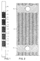
- Figure 1 shows a resistant module, R, obtained by the technique expanded metal, from a metal strip 9 cm wide and 0.18 mm thick.
- This module includes, alternately along the metal strip, expanded metal mesh portions, G1-G5, and portions not screened, K1-K6, pierced with a hole, H1-H6.
- the non-screened portions K2 to K5 occupy a length of 2.8 cm on the strip while the non-screened end portions of module, K1, K6, have a length of 22.5cm and constitute tabs intended for connection to the module.
- the resistant module according to the Figure 1, as it was produced, has a resistance of 1.04 ohm.
- Figure 2 is an enlarged partial view of part of Figure 1 with, in particular, the mesh portion G2 and the holes H3 and H4.
- FIGS 3 and 4 are simplified views showing how 48 modules according to figure 1 are connected in series to constitute a load 50 ohm power, 150 kW, for use as an antenna fictitious.
- Figure 3 shows the load seen from the front with the 48 modules, such than R, mounted in series in vertical planes perpendicular to the plane of the figure; the mesh portions of the modules are represented by elongated rectangles while the non-meshed portions are shown by continuous lines.
- the 48 modules are kept inside a metal cabinet P, without front face and without rear face but with, at inside, six horizontal insulating bars B1-B6 which pass through the module holes and four vertical metal plates, P1-P4, parallel to the planes of the modules and, therefore, perpendicular to the plane of the figure 3.
- the P1-P4 plates geographically separate the modules into three groups of 16 modules but electrically the three groups are in series.
- the leftmost module in Figure 3 is connected to the cabinet metallic P by a link M while the rightmost module is connected to an access point, N, of the load, symbolized by a rectangle.
- Figure 4 shows the load viewed from the side with the metal cabinet P and another metal cabinet Q, without front or rear face, attached to the cabinet P.
- the contents of the cabinets P and Q are shown, as seen by transparency ; for the cabinet P this content has been represented diagrammatically by the resistant module, R, of FIG. 3.
- the cabinet Q for its part, contains a fan, V, with a maximum flow rate of 23,000 m 3 / h and deflection plates Y1, Y2.
- the fan V draws air from the space located, in Figure 3, to the left of the cabinet Q and blows it via the plates Y1, Y2 on the resistant modules such as R.
- the charge according to Figures 3 and 4 can be compared to a series of 48 quadrupoles each having a capacitor, C1..Ci..C47, C48, in shunt and an inductor, L1 ... Li .. L47, L48, and a resistor, r1 ... ri ... r47, r48 in series.
- the resistors have a value of 1.04 ohms as indicated during the description of FIG. 1.
- the inductors and the capacitors would represent, for a power load carried out in a conventional manner, parasitic capacitances and inductances; in the embodiment which is described here, some of these capacitors, C1, C2, C6, C9, C12, C18, C24, C30, C36, C42, C48 are in fact the sum of a parasitic capacitance and a fixed capacitor of given value.
- These fixed capacitors are mounted between the wall of the metal cabinet P and the end of some of the resistant modules; they are intended to compensate for the load in its operating frequencies so that it has an acceptable standing wave or TOS (standing-wave ratio or SWR) rate.
- the TOS is calculated at the input of the load; this calculation is carried out with the concern of obtaining the desired TOS by means of a minimum number of suitably distributed capacitors; it is therefore an optimization and, in fact, it is not a calculation of TOS which is carried out but a succession of calculations of TOS, these calculations being relative to different distributions of capacitors along the resistive load properly said, and to different values assigned to these capacitors.
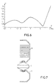
- the desired TOS must not exceed 1.15 from 0 to 1.7 MHz and must not exceed 1.5 from 1.7 to 5 MHz, these successive calculations have resulted in taking eleven capacitors distributed as indicated in FIG.
- Figure 6 shows the waveform variation curve stationary, T, as a function of the frequency F at the input of the load which has just been described. This curve shows that the standing wave rate is less than 1.15 not just up to 1.7 MHz as desired but up to just over 2.5 MHz and up to 5 MHz not only does it does not exceed 1.5 but remains less than or equal to 1.4.
- FIG. 7 shows, as an example, how to mount a capacitor, C, between the wall of the metal cabinet P and the modules resistant.
- Capacitor C is connected to the resistive modules by a finned radiator D and is connected to the cabinet wall by a bracket metallic E; the finned radiator is intended to ensure, between the module resistive whose temperature can reach 300 ° C and the capacitor, a sufficient temperature gradient to prevent the capacitor from being damaged.
- the capacitor is a capacitor fitted with screw outputs; in the case of capacitors fitted with wire, tab or other type of outputs, the radiator D and caliper E are adapted to the outputs considered as well as the connections between these parts and the condenser outputs: connection by welding, screwing or other.
- the present invention is not limited to the example described, it extends to all realizations of loads with resistant metal element deployed with a frequency compensation circuit made of bypass capacitors distributed along the resistive element; and in in particular, the invention applies to such embodiments even if they do not do not have forced ventilation but only cooling by natural convection of the ambient air, and are therefore much more limited in power.
Landscapes
- Physics & Mathematics (AREA)
- General Physics & Mathematics (AREA)
- Engineering & Computer Science (AREA)
- General Engineering & Computer Science (AREA)
- Amplifiers (AREA)
- Waveguide Aerials (AREA)
- Emergency Protection Circuit Devices (AREA)
- Shielding Devices Or Components To Electric Or Magnetic Fields (AREA)
- Non-Reversible Transmitting Devices (AREA)
Description
- la figure 1, un module résistant utilisé dans une charge selon l'invention,
- la figure 2, une partie du module résistant selon la figure 1,
- les figures 3 et 4, une charge selon l'invention, vue de face et de côté,
- la figure 5, un schéma électrique relatif à la charge selon les figures 3 et 4,
- la figure 6, une courbe représentative d'une caractéristique de la charge selon les figures 3 et 4,
- et la figure 7, des composants utilisés dans la charge selon les figures 3 et 4.
| C1 | 100 nF , | 88 V eff , | 89 A eff |
| C2 | 24 nF , | 122 V eff , | 29 Aeff |
| C6 | 3,3 nF , | 466 V eff , | 16 A eff |
| C9 | 2,2 nF, | 726 V eff , | 16 A eff |
| C12 | 1,8 nF, | 948 V eff , | 17 A eff |
| C18 | 1,5 nF , | 1327 V eff , | 20 A eff |
| C24 | 920 pF , | 1633 V eff , | 15 A eff |
| C30 | 560 pF , | 1905 V eff , | 11 A eff |
| C36 | 330 pF , | 2171 V eff , | 7 A eff |
| C42 | 240 pF , | 2450 V eff , | 6 A eff |
| C48 | 160 pF , | 2740 V eff , | 5 A eff |
Claims (5)
- Charge de puissance à refroidissement par air, comportant un assemblage série de modules résistants (R) sensiblement plans, en métal déployé, une structure support métallique (P, Q, P1-P4) et des éléments isolants (B1-B6) pour maintenir l'assemblage, caractérisée en ce que, de manière à être utilisable en radiofréquences, elle est munie de moyens de compensation en fréquence, ces moyens de compensation comportant des liaisons capacitives (C1, C2, C6, C9, C12, C18, C24, C30, C36, C42, C48) pour, parmi certaines extrémités des modules, en relier chacune une à la structure support.
- Charge selon la revendication 1, comportant des moyens de ventilation (Y, Y1, Y2) pour assurer une ventilation forcée des modules, caractérisée en ce que les moyens de compensation en fréquence sont localisés en des endroits où ils subissent eux aussi une ventilation forcée de la part des moyens de ventilation.
- Charge selon l'une des revendications précédentes, caractérisée en ce que au moins certaines des liaisons capacitives comportent en série, en plus d'un condensateur proprement dit (C), un élément dissipateur d'énergie (D).
- Charge selon la revendication 3, caractérisée en ce que l'élément dissipateur d'énergie est du type radiateur à ailettes et en ce que les ailettes du radiateur sont disposées dans des plans parallèles au plan dans lequel est disposé le module à l'extrémité de laquelle la liaison capacitive considérée est reliée.
- Antenne fictive, caractérisée en ce qu'elle est constituée par une charge selon au moins l'une des revendications précédentes.
Applications Claiming Priority (2)
| Application Number | Priority Date | Filing Date | Title |
|---|---|---|---|
| FR9404169A FR2718584B1 (fr) | 1994-04-08 | 1994-04-08 | Charge de puissance à refroidissement par air et antenne fictive constituée par une telle charge. |
| FR9404169 | 1994-04-08 |
Publications (2)
| Publication Number | Publication Date |
|---|---|
| EP0676823A1 EP0676823A1 (fr) | 1995-10-11 |
| EP0676823B1 true EP0676823B1 (fr) | 1998-11-25 |
Family
ID=9461895
Family Applications (1)
| Application Number | Title | Priority Date | Filing Date |
|---|---|---|---|
| EP95400748A Expired - Lifetime EP0676823B1 (fr) | 1994-04-08 | 1995-04-04 | Charge de puissance à refroidissement par air et antenne fictive |
Country Status (5)
| Country | Link |
|---|---|
| US (1) | US5488334A (fr) |
| EP (1) | EP0676823B1 (fr) |
| CA (1) | CA2146199A1 (fr) |
| DE (1) | DE69506159T2 (fr) |
| FR (1) | FR2718584B1 (fr) |
Families Citing this family (5)
| Publication number | Priority date | Publication date | Assignee | Title |
|---|---|---|---|---|
| GB2323479A (en) * | 1997-03-19 | 1998-09-23 | Eaton Ltd | Mounting resistor elements |
| US6014636A (en) * | 1997-05-06 | 2000-01-11 | Lucent Technologies Inc. | Point of sale method and system |
| DE102004033680B4 (de) * | 2004-07-09 | 2009-03-12 | Wobben, Aloys, Dipl.-Ing. | Lastwiderstand |
| CZ304364B6 (cs) * | 2013-03-25 | 2014-03-26 | České vysoké učení technické v Praze - Fakulta elektrotechnická | Kompenzovaná vysokofrekvenční zátěž |
| WO2015075761A1 (fr) | 2013-11-20 | 2015-05-28 | 株式会社辰巳菱機 | Dispositif de test avec charge |
Family Cites Families (9)
| Publication number | Priority date | Publication date | Assignee | Title |
|---|---|---|---|---|
| US1563363A (en) * | 1921-07-22 | 1925-12-01 | Westinghouse Electric & Mfg Co | Resistor |
| GB395363A (en) * | 1932-01-12 | 1933-07-12 | Expanded Metal | Improvements in or relating to electrical resistances, heaters and the like |
| US2087573A (en) * | 1934-11-05 | 1937-07-20 | Expanded Metal | Electrical resistance and electrical heater and method of producing the same |
| US2825874A (en) * | 1954-03-03 | 1958-03-04 | Itt | Artificial load for broad frequency band |
| GB1134091A (en) * | 1965-02-08 | 1968-11-20 | Marconi Co Ltd | Improvements in or relating to the dissipation of radio transmitter output power |
| US4151398A (en) * | 1975-07-31 | 1979-04-24 | Gould Inc. | Clothes dryer heating unit |
| FR2540281A1 (fr) * | 1983-01-31 | 1984-08-03 | Thomson Csf | Charge hyperfrequence a liquide conducteur, pour generateur de grande puissance |
| US5113171A (en) * | 1990-12-21 | 1992-05-12 | General Electric Company | High-frequency current-viewing resistor |
| US5396198A (en) * | 1992-09-09 | 1995-03-07 | Hitachi, Ltd. | Electronic circuit device having a series connection of resistor and capacitance as a noise reducing circuit connected to a power source wiring |
-
1994
- 1994-04-08 FR FR9404169A patent/FR2718584B1/fr not_active Expired - Fee Related
-
1995
- 1995-04-03 CA CA002146199A patent/CA2146199A1/fr not_active Abandoned
- 1995-04-04 EP EP95400748A patent/EP0676823B1/fr not_active Expired - Lifetime
- 1995-04-04 DE DE69506159T patent/DE69506159T2/de not_active Expired - Fee Related
- 1995-04-06 US US08/417,767 patent/US5488334A/en not_active Expired - Fee Related
Also Published As
| Publication number | Publication date |
|---|---|
| FR2718584A1 (fr) | 1995-10-13 |
| DE69506159T2 (de) | 1999-04-29 |
| DE69506159D1 (de) | 1999-01-07 |
| FR2718584B1 (fr) | 1996-05-31 |
| EP0676823A1 (fr) | 1995-10-11 |
| CA2146199A1 (fr) | 1995-10-09 |
| US5488334A (en) | 1996-01-30 |
Similar Documents
| Publication | Publication Date | Title |
|---|---|---|
| EP0676823B1 (fr) | Charge de puissance à refroidissement par air et antenne fictive | |
| FR2482384A1 (fr) | Dispositif de combinaison de puissance pour un circuit integre hyperfrequence | |
| FR2556510A1 (fr) | Antenne periodique plane | |
| FR2762729A1 (fr) | Diviseur de puissance rf | |
| JP2020136910A5 (fr) | ||
| WO2022195437A1 (fr) | Circuit de polarisation en bande de base et rf, et circuit amplificateur de puissance rf le comprenant | |
| FR2533777A1 (fr) | Oscillateur hyperfrequence de puissance | |
| EP0110768B1 (fr) | Condensateur multi-couches de puissance | |
| EP0203663B1 (fr) | Oscillateur hyperfréquence de puissance, modulé linéairement sur une grande plage de fréquence | |
| FR2725571A1 (fr) | Filtre passe-bas pour applications a haute puissance | |
| BE360400A (fr) | ||
| RU2807424C1 (ru) | Фильтр СВЧ | |
| EP1086507B1 (fr) | Composant passif hyperfrequence a charge resistive | |
| EP0368740A1 (fr) | Boîtier de circuit intégré de haute densité | |
| FR2540282A1 (fr) | Charge hyperfrequence a impedance d'entree stabilisee | |
| EP0814563A1 (fr) | Dispositif d'alimentation impulsionnelle à réseau de bobinages | |
| FR2699345A1 (fr) | Etage de sortie d'un circuit électrique. | |
| BE405243A (fr) | ||
| CH185298A (fr) | Appareil à tubes thermioniques pour ondes très courtes. | |
| CH100880A (fr) | Amplificateur-détecteur pour la télégraphie et la téléphonie sans fil. | |
| CA3163231A1 (fr) | Dispositif pour connecter une source de puissance a un inducteur | |
| CH129202A (fr) | Antenne de radiocommunication. | |
| BE483414A (fr) | ||
| CH221099A (fr) | Dispositif de protection pour circuits électriques. | |
| BE378237A (fr) |
Legal Events
| Date | Code | Title | Description |
|---|---|---|---|
| PUAI | Public reference made under article 153(3) epc to a published international application that has entered the european phase |
Free format text: ORIGINAL CODE: 0009012 |
|
| AK | Designated contracting states |
Kind code of ref document: A1 Designated state(s): CH DE FR GB LI |
|
| 17P | Request for examination filed |
Effective date: 19960126 |
|
| GRAG | Despatch of communication of intention to grant |
Free format text: ORIGINAL CODE: EPIDOS AGRA |
|
| 17Q | First examination report despatched |
Effective date: 19980220 |
|
| GRAG | Despatch of communication of intention to grant |
Free format text: ORIGINAL CODE: EPIDOS AGRA |
|
| GRAH | Despatch of communication of intention to grant a patent |
Free format text: ORIGINAL CODE: EPIDOS IGRA |
|
| GRAH | Despatch of communication of intention to grant a patent |
Free format text: ORIGINAL CODE: EPIDOS IGRA |
|
| GRAA | (expected) grant |
Free format text: ORIGINAL CODE: 0009210 |
|
| AK | Designated contracting states |
Kind code of ref document: B1 Designated state(s): CH DE FR GB LI |
|
| REG | Reference to a national code |
Ref country code: CH Ref legal event code: EP |
|
| REF | Corresponds to: |
Ref document number: 69506159 Country of ref document: DE Date of ref document: 19990107 |
|
| GBT | Gb: translation of ep patent filed (gb section 77(6)(a)/1977) |
Effective date: 19990128 |
|
| PG25 | Lapsed in a contracting state [announced via postgrant information from national office to epo] |
Ref country code: LI Free format text: LAPSE BECAUSE OF NON-PAYMENT OF DUE FEES Effective date: 19990430 Ref country code: CH Free format text: LAPSE BECAUSE OF NON-PAYMENT OF DUE FEES Effective date: 19990430 |
|
| PLBE | No opposition filed within time limit |
Free format text: ORIGINAL CODE: 0009261 |
|
| STAA | Information on the status of an ep patent application or granted ep patent |
Free format text: STATUS: NO OPPOSITION FILED WITHIN TIME LIMIT |
|
| 26N | No opposition filed | ||
| REG | Reference to a national code |
Ref country code: CH Ref legal event code: PL |
|
| REG | Reference to a national code |
Ref country code: GB Ref legal event code: IF02 |
|
| PGFP | Annual fee paid to national office [announced via postgrant information from national office to epo] |
Ref country code: DE Payment date: 20080411 Year of fee payment: 14 |
|
| PGFP | Annual fee paid to national office [announced via postgrant information from national office to epo] |
Ref country code: FR Payment date: 20080414 Year of fee payment: 14 |
|
| PGFP | Annual fee paid to national office [announced via postgrant information from national office to epo] |
Ref country code: GB Payment date: 20080409 Year of fee payment: 14 |
|
| GBPC | Gb: european patent ceased through non-payment of renewal fee |
Effective date: 20090404 |
|
| REG | Reference to a national code |
Ref country code: FR Ref legal event code: ST Effective date: 20091231 |
|
| PG25 | Lapsed in a contracting state [announced via postgrant information from national office to epo] |
Ref country code: DE Free format text: LAPSE BECAUSE OF NON-PAYMENT OF DUE FEES Effective date: 20091103 |
|
| PG25 | Lapsed in a contracting state [announced via postgrant information from national office to epo] |
Ref country code: GB Free format text: LAPSE BECAUSE OF NON-PAYMENT OF DUE FEES Effective date: 20090404 Ref country code: FR Free format text: LAPSE BECAUSE OF NON-PAYMENT OF DUE FEES Effective date: 20091222 |