EP0677328A1 - Verfahren zum Betrieb einer vertikalen Prallmühle - Google Patents
Verfahren zum Betrieb einer vertikalen Prallmühle Download PDFInfo
- Publication number
- EP0677328A1 EP0677328A1 EP95105462A EP95105462A EP0677328A1 EP 0677328 A1 EP0677328 A1 EP 0677328A1 EP 95105462 A EP95105462 A EP 95105462A EP 95105462 A EP95105462 A EP 95105462A EP 0677328 A1 EP0677328 A1 EP 0677328A1
- Authority
- EP
- European Patent Office
- Prior art keywords
- rotor
- tips
- stones
- vertical shaft
- type impact
- Prior art date
- Legal status (The legal status is an assumption and is not a legal conclusion. Google has not performed a legal analysis and makes no representation as to the accuracy of the status listed.)
- Granted
Links
Images



Classifications
-
- B—PERFORMING OPERATIONS; TRANSPORTING
- B02—CRUSHING, PULVERISING, OR DISINTEGRATING; PREPARATORY TREATMENT OF GRAIN FOR MILLING
- B02C—CRUSHING, PULVERISING, OR DISINTEGRATING IN GENERAL; MILLING GRAIN
- B02C13/00—Disintegrating by mills having rotary beater elements ; Hammer mills
- B02C13/14—Disintegrating by mills having rotary beater elements ; Hammer mills with vertical rotor shaft, e.g. combined with sifting devices
- B02C13/18—Disintegrating by mills having rotary beater elements ; Hammer mills with vertical rotor shaft, e.g. combined with sifting devices with beaters rigidly connected to the rotor
- B02C13/1807—Disintegrating by mills having rotary beater elements ; Hammer mills with vertical rotor shaft, e.g. combined with sifting devices with beaters rigidly connected to the rotor the material to be crushed being thrown against an anvil or impact plate
- B02C13/1814—Disintegrating by mills having rotary beater elements ; Hammer mills with vertical rotor shaft, e.g. combined with sifting devices with beaters rigidly connected to the rotor the material to be crushed being thrown against an anvil or impact plate by means of beater or impeller elements fixed on top of a disc type rotor
-
- B—PERFORMING OPERATIONS; TRANSPORTING
- B02—CRUSHING, PULVERISING, OR DISINTEGRATING; PREPARATORY TREATMENT OF GRAIN FOR MILLING
- B02C—CRUSHING, PULVERISING, OR DISINTEGRATING IN GENERAL; MILLING GRAIN
- B02C13/00—Disintegrating by mills having rotary beater elements ; Hammer mills
- B02C13/14—Disintegrating by mills having rotary beater elements ; Hammer mills with vertical rotor shaft, e.g. combined with sifting devices
- B02C13/18—Disintegrating by mills having rotary beater elements ; Hammer mills with vertical rotor shaft, e.g. combined with sifting devices with beaters rigidly connected to the rotor
- B02C13/1807—Disintegrating by mills having rotary beater elements ; Hammer mills with vertical rotor shaft, e.g. combined with sifting devices with beaters rigidly connected to the rotor the material to be crushed being thrown against an anvil or impact plate
- B02C2013/1885—Disintegrating by mills having rotary beater elements ; Hammer mills with vertical rotor shaft, e.g. combined with sifting devices with beaters rigidly connected to the rotor the material to be crushed being thrown against an anvil or impact plate of dead bed type
Definitions
- the present invention relates to a vertical shaft type impact crusher and an operation method for a vertical shaft type impact crusher. More paticularly, the present invention relates to a vertical shaft type impact crusher and an operation method for a vertical shaft type impact crusher for crushing bulk materials, for example, natural rock, into grains or particles of desired size.
- Bulk materials e.g., natural rock
- a vertical shaft type impact crusher One type of crusher used for such a crushing process is known as a vertical shaft type impact crusher.
- Impact crushers operate on the basis of the principle that rock is accelerated at a high speed so as to collide with an impact surface, thereby crushing the rock.
- Such impact crushers may be generally divided into two types according to the mode of crushing: anvil type and dead stock type.
- the anvil type impact crusher includes a rotor having a plurality of wings or blades on the upper side thereof being rotated at a high speed, whereby raw stones cast into the crusher are accelerated by the blades and centrifugally discharged so as to collide with anvils which are disposed in a ring shape around the rotor, thereby crushing the raw stones.
- Such an anvil type impact crusher is mainly used for the purpose of crushing raw stones having a relatively large diameter by collision to thereby reduce the size of the raw stones.
- the dead stock type impact crusher is mainly used to smooth surfaces of raw stones which has already been crushed into gravel of desired size and to make the grain size uniform.
- a dead stock type impact crusher is similar to the anvil type impact crusher in that raw stones are accelerated by blades, but different from the latter in that dead stocks are formed from crushed raw stones at the periphery of the rotor, and the surfaces having angles of rest formed by this dead stock are used as impact surfaces for crushing raw stones.
- Crushed Stone JIS 5005 is defined as the weight-percentage of stones passing through sieves as follows: 60mm 100%; 50mm 95 100%; 25mm 35 70%; 15 mm 10 30%; 5 mm 0 5%;.
- a further problem is in that tips are worn by accelerated stones.
- a rotor is provided with pairs of tips mounted on the wings thereof. Stones of a large size, the diameter of which is larger than 40 mm, generate more chipping-wearing than stones of a small size. Material harder to chip is preferably applied for tips which are used in a crusher for crushing stones of a large size. Stones of small size, the diameter of which is smaller than 40 mm, generate more ordinal wearing than stone of a large size. A higher degree of wear-resistant material is preferably applied for tips which are used in a crusher for crushing stones to a small size. As such, there is an inconsistency in the tips used in impact crushers for large sized stone-crushing and those used for small sized stone-crushing.
- An object of the present invention is to provide a vertical shaft type impact crusher for crushing stones of various sized which overcomes the inconsistency of stones of a large size generating more chipping-wearing than those of a small size, thereby material hard to chip being preferably applied for tips which are used in a crusher for crushing stones of a large size while stones of a small size generate more ordinal wearing than stones of a large size, thereby a higher degree of wear-resistant material being preferably applied for tips which are used in a crusher for crushing stones of a small size.
- Another object of the present invention is to provide a vertical shaft type impact crusher for crushing stones of various sizes which has a high production efficiency.
- Still another object of the present invention is to provide an operation method for a vertical shaft type impact crusher for crushing stones of various sizes, the life time of the tips being extended.
- Still another object of the present invention is to provide an operation method for a vertical shaft type impact crusher for crushing stones of various sizes, a plurality of the crushers being simultaneously operated, where the production efficiency is high.
- Still another object of the present invention is to provide an operation method for a vertical shaft type impact crusher for crushing stones of various sizes, a plurality of crushers being simultaneously operated, the life time of tips being extended.
- the vertical shaft type impact crushers have a rotor mounted on a casing body, the rotor being reversely rotatable for giving thrown stones centrifugal force and anvils for crushing stones discharged from the rotor.
- the anvils are mounted in the circumferential area around the rotor. Dead stock spaces for crushed stones to be accumulated therein are located in the circumferential area around the rotor. The anvils are located between the respective dead stock spaces with respective intervals given in the peripheral direction around the rotor.
- the vertical shaft type impact crushers have a dead stock forming plate for forming dead stock spaces thereabove.
- the dead stock forming plate is located around the rotor and has a bore in which the rotor is located.
- the vertical shaft type impact crushers have an adjustable means for adjusting the distance between the respective anvils and the rotor.
- the adjustable means being located between the respective anvils and the inner surface of the casing body.
- the bore is circular, and furthermore has a ring for adjusting the volume of the dead stock spaces.
- the ring is replaceably mounted on the peripheral edge of the circular bore.
- the vertical shaft type impact crushers have a rotor mounted on the casing body.
- the rotor is reversely rotatable for giving thrown stones centrifugal force.
- the vertical shaft type impact crushers have anvils mounted in the circumferential domain around the rotor.
- the rotor includes multiple pairs of tips, the respective pairs of tips being located in symmetry with respect to the respective central lines in angular orientations with the respectively equal angular intervals.
- the center lines extend from and are perpendicular to the axis line of the rotor in the radial direction.
- the respective tips of the respective pairs which point forward in the rotaional direction with respect to the respective center lines are made of hard material in comparison with material in what follows.
- the respective tips of the respective pairs which point backward in the rotational direction with respect to the respective center lines are made of soft material in comparison with the above hard material.
- hard material is applied for the forward-pointing tips mounted in the respective dead stock spaces where respective dead stocks are formed on the rotor rotated in the regularly rotational direction
- soft material is applied for the front tips mounted in the respective dead stock spaces where respective dead stocks are formed on the rotor rotated in the reversely rotational direction.
- the rotation of the rotor in the regular direction or in the reverse direction is operated in response to the grain size of raw stones.
- the rotor in the operation method for the vertical shaft type impact crushers, the rotor is rotated in the regular direction in the case where the grain size of the raw stone is large and the rotor is rotated in the reverse direction in the case where the grain size of raw stone is small.
- the rotation of the rotor in the regular direction or in the reverse direction is operated in response to the degree of wear of the hard tips in comparison with that of the soft tips.
- the rotor of the first crusher into which stones of a large grain size are thrown down is rotated in the regular direction
- the rotor of the second crusher into which stones of a small grain size are thrown down is rotated in the reverse direction.
- the vertical shaft type impact crushers have a rotor mounted on the casing body and which is reversely rotatable for giving thrown stones centrifugal force.
- the crushers have dead stock spaces for crushed stones to be accumulated therein.
- the dead stock spaces are located in the circumferential area around the rotor.
- the anvils for crushing stones discharged from the rotor are mounted in the circumferential area around the rotor.
- the respective anvils are located between said respective dead stock spaces with respective intervals given in the peripheral direction around the rotor which includes multiple pairs of tips, the respective pairs of tips being located in symmetry with respect to the respective central lines in the angular orientations with the respective equal angular intervals given, the center lines extending from the axis line of the rotor in the radial direction.
- Respective tips of the pairs which point forward in the rotaional direction with respect to the respective center lines are made of hard material in comparison with material in what follows.
- Respective tips of the pairs which point backward in the rotaional direction with respect to the respective center lines are made of soft material in comparison with the above hard material.
- the wearing of harder tips brought about by the collision with stones of a large size is less because of the regularly rotaional direction.
- the wearing of softer tips brought about by the collision with stones of a small size is less because of the reversely or irregularly rotaional direction.
- Fig.1 is a top view of a first embodiment of a vertical shaft type impact crusher in accordance with the present invention.
- Fig.2 is a cross-sectional view of the crusher of Fig.1.
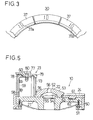
- Fig.3 is a top view of a dead stock space of another embodiment.
- Fig.4 is a horizontal cross-sectional view of Fig.1.
- Fig.5 is a vertical cross-sectional view of the rotor of the crusher of Fig.1.
- FIGs. 1 and 2 illustrate a veritical shaft-type impact crusher.
- a casing 1 includes a casing body 1a and a covering lid 1b. Covering lid 1b is rotatably mounted on the upper portion of the casing body 1a by means of a mounting means( not shown ).
- Covering lid 1b is opened and closed relative to the casing body 1a by means of a lever 5 which rotates together with a rotating axis and is forced upwardly and downwardly by a hydraulic cylinder 4.
- Covering lid 1b has a shooting opening 2.
- Two guiding shoots 7 and 8 are located at the respective lower positions of the shooting opening 2, affixed to the suspended portion of the casing body 1a.
- Lower guiding shoot 8 is attaced to a multiple number of veritically suspended libs 8a located on a circular line. Veritically suspended libs 8a are provided as a portion of the casing body 1a.
- a roter 10 is located under the guiding shoot 8. Roter 10 is mounted on a top surface of the veritical rotating shaft 11. Vertical rotating shaft 11 is rotably supported in the axle-housing 15 through bearings 13 and 14. Axle-housing 15 is mounted on the casing body 1a through brackets 16. A pulley 17 is attaced to the lower portion of the veritical rotating shaft 11. Pulley 17 is connected to a reversible mortor( not shown ) through a belt( not shown ). Vertical rotating shaft 11 is rotated back and forth in response to the operation of the motor.
- Rortor 10 includes a rotor body 21, a distributing cone-like body 22, three wings 23, 23, 23 and three pairs of liners 24.
- Distributing cone-like body 22 is mounted on the upper side of the central portion of the rotor body 21.
- Respective three wings 23, 23, 23 are adjustably provided in three angular orientations with the respective equal angular intervals of 120 degrees there between.
- Respective pairs of liners are respectively placed between the respective wings of the respective 120 degrees-angular intervals.
- Casing 1 is generally a square in the sectional view.
- a dead stock forming plate 30 is horizontally disposed in the casing body 1a.
- Dead stock forming plate 30 is designed as a square plate of which the circumferential edge portion is affixed against the inner surface of the casing body 1a.
- dead stock forming plate 30 has a circular opening 31, the diameter of which is designed to be larger than that of the rotor 10. Circular opening 31 and rotor10 have a common central axis-line.
- Four anvils 32a, 32b, 32c,32d are located upwardly apart from the dead stock forming plate 30. Respective anvils 32a, 32b, 32c,32d have respective anvil members 33 affixed to the respective central portions of the inner surfaces of the casing body 1a.
- Each anvil member is made of an ordinary wear-resitant material, e.g., manganese steel.
- the location off of anvils 32 creates four dead stock spaces 34a, 34b, 34c, 34d to be formed therebetween.
- Respective dead stock spaces 34a, 34b, 34c, 34d are respectively provided as four coneer portions partly forming the inner space of the casing 1.
- Each horizontal distance between each anvil and the rotor 10 is adjustable as follows.
- Spacers 35 are replaceably inserted between the respective surfaces of the casing body 1a and the respective anvil members. The number of the spacers 35 enables the above distance in the horizontal direction to be adjustable.
- the volume of the dead stock spaces 34a, 34b, 34c, 34d are also adjustable as follows. As shown in Figs 1 and 2, diameter-adjusting ring 36 is located at the circumferential edge of the circular openig 31. Adjusting ring 36 is in the circumferential direction divided into a multiple of pieces of segments 37. Each segment is replaceably affixed to the dead stock forming plate 30 by means of each bolt 38.
- Each flange 41 is formed as each inner circumferential edge portion of the respective segment 37.
- Many kinds of segment groups, the radiuses of which are different from one another, are allowable to be prepared. The replacement of the segment group allows the above volumes of the dead stock spaces 34 to be altered.
- a multiple number of one-body rings may be used for alternation of the ring diameter.
- FIG.3 Another embodiment of a diameter-adjusting ring is illustrated in Fig.3.
- a segment 37 has an elongated hole 37a extending in the radial direction.
- the mounting position of the segment 37 relative to the dead stock forming plate 30 is aligned in the radial direction.
- Each segment is secured to the dead stock forming plate 30 by means of a bolt( not shown In Fig.3 ) passing through the elongated hole 37a.
- a space is formed between the neighborhood relation of segments 37,37. Such a space does not cause any trouble, each space being filled with crushed rocks.
- FIGs.4 and 5 illustrate the detailed structure of rotor 10.
- a liner 50 to protect the rotor body 21 is fittedly mounted on the outer periphery of the rotor body 21.
- Liner 50 is bolted to the rotor body.
- a flat plane 52 is formed as the top surface of the distributing cone-like body in the center of the upper side of the distributing cone-like body 22.
- the outer periphery of the distributing cone-like body 22 is formed to be tapered as a tapered surface 53 around the rotor axis line.
- a circular recess 54 is formed on the lower side of the distributing cone-like body 22.
- Recess 30 engages with a circular step portion 55 formed on the top surface of the rotor body 21, thereby causing the distributing cone-like body 22 to be located at the proper position.
- the distributing cone-like body 22 has a bore 56 in the center thereof, allowing an engaging portion of a suspending means( not shown ) to be engaged therewith during assembly and disassembly.
- Each wing 23 includes respective support 57.
- Supports 57 are fixedly mounted on the rotor body 21.
- Supports 57 are disposed on the outer peripheral zone around the distributing cone-like body 22.
- Supports 57 are provided as three bodies disposed in the three angular orientations with the respectively equal angular intervals of 120 degrees therebetween.
- Each supports 57 includes a radially extending portion 58, circumferentially extending portion 59 and a plate portion 60.
- Radially extending portion 58 extends in the radial direction on the rotor body 21, while the circumferentially extending portion 59 generally extends in the circumferential back-and-forth directions on the rotor body 21 from the outer portion of the radially extending portion 58.
- Discharge passage liners 24 are located between a pair of supports 57,57 with the above descrived respective angular intervals.
- Projection 61 is fitted into a recess 62 provided on the upper side of the rotor body 21, thereby effecting the positioning of the discharge passage liner 24.
- a first wall liner 64 is fixedly mounted on the outside of the support 57. Studbolts 65 as screwed portions in one body are provided with the first wall liner 64. Nuts are fittedly inserted into the studbolts 65 of the first wall liner 64, by which the first wall liner 64 is secured to the circumferentially extending portion 59 of the supports 57. On the circumferentially extending portion 59 of the supports 57 are mounted second wall liners 66, third wall liner 67 and outer tip plates 68. Studbolts 71 as screwed portions in one body are provided with the second wall liner 66. Third wall liner 67 is secured at the medium position between the second wall liner 66 and the circumferentially extending portion 59 by means of the studbolts 71 and nuts( not shown ) fitted into the studbolts 71.
- super-hardness tips or non-super-hardness tips 72 are mounted on the base body 69 of the outer tip plates 68.
- Non-super-hardness tip 72 is made of hard steel or hard alloy, e.g., Cr-steel, Ni-Cr-steel, that is, more easily worn but hard to chip because of its pliability.
- the expression “to be hard to chip” means, in strength of material, that chipping wear is comparably less.
- the expression "super-hardnes” in Japanese wording means that the super-hardness of steel or super-hardness of alloy is not easier to wear but is easier to chip.
- the expression "to be easy to chip” means, in strength of material, that chipping wear is comparably more.
- super-hard alloys are known as sintered alloys, included in WC-Co series, WC-TiC-Co series, WC-TiC-TaC( NbC )-Co series, TaC-Ni series, Cr - Ni series that are correspondent in hardness to diamond and made by means of a sintering method where Fe-composition combined with soft carbide is molded under pressure and sintered after molding. It is apparent from the above definition that not only alloy is applied for super-hardness tips, but fine ceramics is also.
- Inner tip plates 73 are disposed on the inner peripheral portion of the supports 57. Innner tip plates 73 are U-shaped with the radially extending portion 58 conceived thereby. Each inner tip plate 73 includes an inside tip and right and left side tips. These tips are made of material of the same kind as the above material for tips 72, that is super-hardness alloy or non-super-hardness alloy as described above.
- a downwardly bended portion 79 is designed as an inner side edge of the top covering plate 77.
- Inner tip plate 73 is secured to and between the downwardly bended portion 79 and the distributing cone-like body 22.
- Top covering plate 77 is affixed to the plate portion 60 of the support 57 and the base body 69 of the outer tip plates 68 by means of a bolt 80 and another bolts( not shown ) at four positions.
- Fig.4 illustrates three center lines L,M,N which are in different angular positions.
- Line L is different from line M by 120 degrees.
- Line M is defferent from Line N by 120 degrees.
- Line N is defferent from Line L by 120 degrees.
- Respective center lines L,M and N are identical to the center lines of the respective radially extending portions 58,58,58 of the supports and are perpendicular to the axis line K of the rotor 10, meeting at one point on the axis line K.
- the three rotor portions 10LM, 10MN and 10NL of the rotor 10 between one voluntary center line and the 2 other center lines next to it and between the 2 other center lines are substantially congruent to each other.
- Wings 23L has symmetry with respect to the center line L.
- Wing 23M has symmetry with respect to the center line M.
- Wings 23N has symmetry with respect to the center line N.
- the base bodies 69 are given as a set of two base bodies 69L1 and 69L2 that are symmetrical in circumference with respect to the center line L.
- the other base bodies 69 are given as a set of two base bodies 69M1 and 69M2 that are symmetrical in circumference with respect to the center line M.
- the still other base bodies 69 are given as a set of two base bodies 69N1 and 69N2 that are symmetrical in circumference with respect to the center line N.
- the tips 72 are fixedly mounted on the two respective base bodies 69L1 and 69L2 as a set of two tips 72L1 and 72L2 that are symmetrical to each other with respect to the center line L.
- the other tips 72 are fixedly mounted on the respective two base bodies 69M1 and 69M2 as a setof two tips 72M1 and 72M2 that are symmetrical to each other with respect to the center line M.
- the still other tips 72 are fixedly mounted on the respective two base bodies 69N1 and 69N2 as a set of two tips 72N1 and 72N2 that are symmetrical to each other with respect to the center line N.
- tip 72L1 and tip 72M2 are located in the rotor portion 10LM
- tip 72M1 and tip 72N2 are located in the rotor portion 10MN
- tip 72N1 and tip 72L2 are located in the rotor portion 10NL.
- One group of tips 72L1, 72M1 and 72N1 that have the respective phases identical with one another in the rotational direction are made of super-hardness material as defined above.
- the other group of tips 72L2, 72M2 and 72N2 that have the respective phases identical with one another in the rotational direction are made of ordinal material that is non-super-hardness material as defined above.
- One group of tips 72L1, 72M1,72N1 and the other group of tips 72L2, 72M2, 72N2 are all replaceable. It is not so necessary to apply a super-hardness-tip for the inner tips 73.
- Dead spaces 91L, 91M and 91N are given in the respective wings 23L, 23M and 23N on the both sides in the rotational(circumferential) direction.
- One group of dead spaces 91L1, 91M1 and 91N1 are in the same phase in the rotational direction.
- the other group of dead spaces 91L2, 91M2 and 91N2 are in the same phase in the rotational direction.
- Dead spaces 91L1 and dead spaces 91L2 are in the respective phases different from each other.
- Dead space 91L1 and dead space 91L2 are in symmetry with respect to the center line L.
- Dead space 91M1 and dead space 91M2 are in symmetry with respect to the center line M.
- Dead space 91N1 and dead space 91N2 are in symmetry with respect to the center line N.
- Each dead space is located between one of the wings 23 and one of the discharge passage liners 24.
- Rortor 10 is driven at a high speed by a driving motor( not shown ).
- Raw rocks are thrown down onto the rotor from the shooting opening 2 through the guiding shoots 7 and 8.
- the thrown raw rocks are distributed by the distributing cone-like body 22 towards any of the discharge passages formed between the respective two neighboring wings.
- Such distributed raw rocks are accelerated with a given centrifugal force. This causes the rocks to be discharged from the peripheral end.
- Such discharged raw stones are crushed into stones with smaller diameters by collision with one of the anvils 32a, 32b, 32c, 32d.
- Some crushed stones are accumulated on the dead stock forming plate 30 of the dead stock spaces 34a, 34b, 34c, 34d.
- accumulated crushed stones do not perfectly form a dead stock.
- a sufficent amount of stones accumulated on the dead stock forming plate 30 form a perfect dead stock.
- four dead stocks 42, 42, 42, 42 are formed with the respective angles of rest. As a result, discharged raw stones are crushed by collosion with such formed dead stocks.
- dead stocks are also formed on the rotor 10 by stones that are prevented from discharging by the supports 57 and the circumferentially extending portion 59. Such dead stocks have the respectively specified angles of rest under operation of centrifugal force and gravitational force. Collision of raw stones with anvil 32 which has a high degree of hardness and is made of manganese steel causes discharged stones to be crushed into a comparably small radia of stones, while collision of raw stones with deas stock 42 which has a low degree of hardness and is formed of accumulated stones causes discharged stones to be crushed into a comparably large radia of stones. It is not suitable that the collision of a stone with a dead stock is expressed as "crush". A stone colliding with a dead stock is reduced little in radius, but is merely made smooth because of surface wear.
- Raw stones that are accelerated and rolled on the surfaces of the dead stocks accumulated on the dead stock forming plate 30 in the dead stock spaces 34a, 34b, 34c, 34d, collide with tips 72. Tips 72 wear less easily but are easier to chip when thrown raw stones are of large grain size. On the other hand, tips 72 are harder to chip but easier to wear when thrown raw stones are of small grain size.
- Cotrolling the operation of a crusher according to the present invention enables the production efficiency to increase.
- Super-hardness tips 72L1, 72M1, 72N1 are applied as tips mounted in the dead stock spaces 91L1, 91M1, 91N1 where dead stocks are formed on the rotor rotating in a given direction(clockwise direction)
- non-super-hardness tips 72L2, 72M2, 72N2 are applied as tips mounted in the dead stock spaces 91L2, 91M2, 91N2 where dead stocks are formed on the rotor rotating in the reverse direction(anti-clockwise direction).
- Operation control includes an operation to rotate the rotor 10 in the clockwise direction or to rotate the rotor 10 in the anti-clockwise direction in correspndence to the grain size or grain size distribution of raw stones.
- the rotor For the large size of stones being produced, that is, raw stones being of large size, the rotor is rotated in the clockwise direction as seen in Fig.4. Most stones collide with the non-super-hardness tips 72L2, 72M2, 72N2 that are less worn because of a lower collision frequency and hard to chip because of its physical properties.
- the rotor For the small size of stones being produced, that is, raw stones being of small size, the rotor is rotated in the anti-clockwise direction. Most stones collide with the non-super-hardness tips 72L1, 72M1, 72N1 that are hard to chip because of their small moments and of less wear because of their physical properties, despite a higher collision frequency.
- Such an operation method is regular but may not be regular in combination with the regular operation.
- the rotor When large sized stones are produced, the rotor may be rotated in the clockwise direction and when small sized stones are produced, the rotor may be rotated in the anti-clockwise direction.
- regular rotation or irregular rotation may be operated. Such a combination of regular operation with irregular operation results in an extension in the common tip life.
- a single crusher is not always used.
- a multiple number of crushers according to the present invention may be simultaneously or synchronously operated. It is normal that a multiple number of crushers are operated in relation to each other. Simultaneous operation enables processes to be synchronous in which stones of a large grain size are in multi-processes crushed into stones of a small grain size of stones. Rortors are rotated in the respective rotational direction in the respective processes: a first step crusher being rotated in the clockwise direction; a second step crusher being rotated in the regular or irregular direction; a third step crusher being rotated in the anti-clock direction. Such a group-control operation results in the extension of the tip life.
Landscapes
- Engineering & Computer Science (AREA)
- Food Science & Technology (AREA)
- Crushing And Pulverization Processes (AREA)
Applications Claiming Priority (3)
| Application Number | Priority Date | Filing Date | Title |
|---|---|---|---|
| JP98155/94 | 1994-04-12 | ||
| JP09815594A JP3249009B2 (ja) | 1994-04-12 | 1994-04-12 | 竪型衝撃式破砕機 |
| JP9815594 | 1994-04-12 |
Publications (2)
| Publication Number | Publication Date |
|---|---|
| EP0677328A1 true EP0677328A1 (de) | 1995-10-18 |
| EP0677328B1 EP0677328B1 (de) | 1999-09-15 |
Family
ID=14212263
Family Applications (1)
| Application Number | Title | Priority Date | Filing Date |
|---|---|---|---|
| EP95105462A Expired - Lifetime EP0677328B1 (de) | 1994-04-12 | 1995-04-11 | Vertikale Prallmühle |
Country Status (4)
| Country | Link |
|---|---|
| US (1) | US5639030A (de) |
| EP (1) | EP0677328B1 (de) |
| JP (1) | JP3249009B2 (de) |
| DE (1) | DE69512122T2 (de) |
Cited By (2)
| Publication number | Priority date | Publication date | Assignee | Title |
|---|---|---|---|---|
| EP1084751A1 (de) * | 1999-09-20 | 2001-03-21 | Van der Zanden, Johannes Petrus Andreas Josephus | Verfahren und Vorrichtung zum synchronisierten und symmetrischen Prallzerkleinern |
| EP3150280A1 (de) * | 2015-10-02 | 2017-04-05 | Kubota Environmental Service Co., Ltd. | Schutzschalterauskleidungsbefestigungsstruktur für einen vertikalen häcksler |
Families Citing this family (12)
| Publication number | Priority date | Publication date | Assignee | Title |
|---|---|---|---|---|
| US5860605A (en) | 1996-10-11 | 1999-01-19 | Johannes Petrus Andreas Josephus Van Der Zanden | Method and device for synchronously making material collide |
| US6149086A (en) * | 1999-03-22 | 2000-11-21 | Cedarapids, Inc. | Shoe mounting bracket for a vertical shaft impact crusher and liner for same |
| US6070820A (en) * | 1999-03-22 | 2000-06-06 | Cedarapids, Inc. | Table reinforcing ring for a vertical shaft impact crusher |
| US6889577B2 (en) * | 2001-09-22 | 2005-05-10 | Afs Trinity Power Corporation | Energy-absorbing housing for high-speed flywheels |
| AUPR858301A0 (en) * | 2001-10-30 | 2001-11-29 | Crushing & Mining Equipment Pty Ltd | An impactor anvil |
| US7335187B2 (en) * | 2003-10-14 | 2008-02-26 | Sda Product, Inc. | Safety dialysis needle/catheter system and method of use |
| US7753303B2 (en) * | 2006-09-21 | 2010-07-13 | Hall David R | Rotary shaft impactor |
| US7866585B2 (en) * | 2006-09-21 | 2011-01-11 | Hall David R | Rotary shaft impactor |
| CN102728435B (zh) * | 2011-04-15 | 2014-04-16 | 中国水电顾问集团贵阳勘测设计研究院 | 一种采用高强度岩石制砂的方法 |
| WO2013127507A1 (en) | 2012-02-29 | 2013-09-06 | DICHTER, Ingrid | Impact member for vertical shaft impact crusher |
| KR101551463B1 (ko) * | 2015-01-12 | 2015-09-08 | 박홍준 | 수직축 임팩트 크러셔용 분할 타입 분배판 |
| JP7554451B2 (ja) * | 2020-07-28 | 2024-09-20 | 株式会社中山ホールディングス | 再生骨材生成システム及び再生骨材生成方法 |
Citations (4)
| Publication number | Priority date | Publication date | Assignee | Title |
|---|---|---|---|---|
| US4390136A (en) * | 1981-07-17 | 1983-06-28 | Burk John H | Replacement wear pins and replaceable impeller assembly for impact crusher |
| FR2593723A1 (fr) * | 1986-02-04 | 1987-08-07 | Dragon Yernaux Babbitless | Perfectionnements aux concasseurs a action centrifuge et a axe vertical |
| US4844354A (en) * | 1988-03-05 | 1989-07-04 | Nakayama Iron Works | Centrifugal refining crusher |
| DE9015362U1 (de) * | 1990-11-08 | 1991-01-17 | Christian Pfeiffer Maschinenfabrik GmbH & Co KG, 4720 Beckum | Schleuderbrecher |
Family Cites Families (4)
| Publication number | Priority date | Publication date | Assignee | Title |
|---|---|---|---|---|
| US3652023A (en) * | 1970-03-17 | 1972-03-28 | Bruce V Wood | Impact crusher |
| US3767127A (en) * | 1971-12-20 | 1973-10-23 | B Wood | Impact crusher |
| US4756484A (en) * | 1986-09-22 | 1988-07-12 | Nordberg, Inc. | Vertical shaft impact crusher with interchangeable crusher ring segments |
| JPH04939U (de) * | 1990-04-17 | 1992-01-07 |
-
1994
- 1994-04-12 JP JP09815594A patent/JP3249009B2/ja not_active Expired - Lifetime
-
1995
- 1995-04-10 US US08/419,545 patent/US5639030A/en not_active Expired - Lifetime
- 1995-04-11 EP EP95105462A patent/EP0677328B1/de not_active Expired - Lifetime
- 1995-04-11 DE DE69512122T patent/DE69512122T2/de not_active Expired - Fee Related
Patent Citations (4)
| Publication number | Priority date | Publication date | Assignee | Title |
|---|---|---|---|---|
| US4390136A (en) * | 1981-07-17 | 1983-06-28 | Burk John H | Replacement wear pins and replaceable impeller assembly for impact crusher |
| FR2593723A1 (fr) * | 1986-02-04 | 1987-08-07 | Dragon Yernaux Babbitless | Perfectionnements aux concasseurs a action centrifuge et a axe vertical |
| US4844354A (en) * | 1988-03-05 | 1989-07-04 | Nakayama Iron Works | Centrifugal refining crusher |
| DE9015362U1 (de) * | 1990-11-08 | 1991-01-17 | Christian Pfeiffer Maschinenfabrik GmbH & Co KG, 4720 Beckum | Schleuderbrecher |
Cited By (5)
| Publication number | Priority date | Publication date | Assignee | Title |
|---|---|---|---|---|
| EP1084751A1 (de) * | 1999-09-20 | 2001-03-21 | Van der Zanden, Johannes Petrus Andreas Josephus | Verfahren und Vorrichtung zum synchronisierten und symmetrischen Prallzerkleinern |
| WO2001021313A1 (en) * | 1999-09-20 | 2001-03-29 | Van Der Zanden, Rosemarie, Johanna | Device for synchronously and symmetrically making material collide |
| US6802466B1 (en) | 1999-09-20 | 2004-10-12 | Rosemarie Johanna Van Der Zanden | Device for synchronously and symmetrically making material collide |
| EP3150280A1 (de) * | 2015-10-02 | 2017-04-05 | Kubota Environmental Service Co., Ltd. | Schutzschalterauskleidungsbefestigungsstruktur für einen vertikalen häcksler |
| US10384210B2 (en) | 2015-10-02 | 2019-08-20 | Kubota Environmental Service Co., Ltd. | Breaker liner attachment structure for vertical shredder |
Also Published As
| Publication number | Publication date |
|---|---|
| US5639030A (en) | 1997-06-17 |
| DE69512122D1 (de) | 1999-10-21 |
| JP3249009B2 (ja) | 2002-01-21 |
| EP0677328B1 (de) | 1999-09-15 |
| DE69512122T2 (de) | 2000-01-20 |
| JPH07275727A (ja) | 1995-10-24 |
Similar Documents
| Publication | Publication Date | Title |
|---|---|---|
| EP0677328B1 (de) | Vertikale Prallmühle | |
| US4699326A (en) | Vertical shaft impact crusher with split tub | |
| NZ198307A (en) | Vertical impact pulveriser:secondary mineral feed stream surrounds thrown primary feed | |
| US5845856A (en) | Pin mill type crusher | |
| US4844354A (en) | Centrifugal refining crusher | |
| EP0261913A2 (de) | Vertikaler Schlagbrecher mit auswechselbaren Brecherringsegmenten | |
| JP4443264B2 (ja) | 竪型衝撃式破砕機 | |
| ZA200309906B (en) | Wear resistant center feed impact impeller. | |
| AU2022307422B2 (en) | Mantle for a gyratory or cone crusher | |
| JPH0679189A (ja) | 衝撃式竪型破砕機のロータ | |
| JP3558176B2 (ja) | 竪型衝撃式破砕機の運転方法 | |
| CA2530447C (en) | Device and method for comminuting materials | |
| JP2002028512A (ja) | 縦型破砕装置の破砕部構造 | |
| CN117062671B (zh) | 破碎机转子 | |
| CN112718121B (zh) | 破碎机 | |
| JP4028277B2 (ja) | 遠心破砕機 | |
| AU660558B2 (en) | Quarry pulverizer | |
| JPH06246178A (ja) | 鎖打撃式破砕機 | |
| CN210613878U (zh) | 叶轮组件及破碎机 | |
| EP1952887A1 (de) | Trommelmühle | |
| JP3194009B2 (ja) | 衝撃式破砕機 | |
| US20240226911A1 (en) | Jet mill device | |
| CN2214224Y (zh) | 同轴式多级转子冲击破碎机 | |
| CN2301257Y (zh) | 一种粉碎机 | |
| CN212167615U (zh) | 卧式冲击超细粉碎机 |
Legal Events
| Date | Code | Title | Description |
|---|---|---|---|
| PUAI | Public reference made under article 153(3) epc to a published international application that has entered the european phase |
Free format text: ORIGINAL CODE: 0009012 |
|
| AK | Designated contracting states |
Kind code of ref document: A1 Designated state(s): CH DE FR GB IT LI SE |
|
| 17P | Request for examination filed |
Effective date: 19950901 |
|
| 17Q | First examination report despatched |
Effective date: 19980216 |
|
| GRAG | Despatch of communication of intention to grant |
Free format text: ORIGINAL CODE: EPIDOS AGRA |
|
| GRAG | Despatch of communication of intention to grant |
Free format text: ORIGINAL CODE: EPIDOS AGRA |
|
| GRAH | Despatch of communication of intention to grant a patent |
Free format text: ORIGINAL CODE: EPIDOS IGRA |
|
| GRAH | Despatch of communication of intention to grant a patent |
Free format text: ORIGINAL CODE: EPIDOS IGRA |
|
| GRAA | (expected) grant |
Free format text: ORIGINAL CODE: 0009210 |
|
| AK | Designated contracting states |
Kind code of ref document: B1 Designated state(s): CH DE FR GB IT LI SE |
|
| REG | Reference to a national code |
Ref country code: CH Ref legal event code: EP |
|
| REF | Corresponds to: |
Ref document number: 69512122 Country of ref document: DE Date of ref document: 19991021 |
|
| REG | Reference to a national code |
Ref country code: CH Ref legal event code: NV Representative=s name: PATENTANWAELTE SCHAAD, BALASS, MENZL & PARTNER AG |
|
| ITF | It: translation for a ep patent filed | ||
| ET | Fr: translation filed | ||
| PLBE | No opposition filed within time limit |
Free format text: ORIGINAL CODE: 0009261 |
|
| STAA | Information on the status of an ep patent application or granted ep patent |
Free format text: STATUS: NO OPPOSITION FILED WITHIN TIME LIMIT |
|
| 26N | No opposition filed | ||
| REG | Reference to a national code |
Ref country code: GB Ref legal event code: IF02 |
|
| PGFP | Annual fee paid to national office [announced via postgrant information from national office to epo] |
Ref country code: SE Payment date: 20080318 Year of fee payment: 14 |
|
| PGFP | Annual fee paid to national office [announced via postgrant information from national office to epo] |
Ref country code: DE Payment date: 20080424 Year of fee payment: 14 Ref country code: CH Payment date: 20080416 Year of fee payment: 14 |
|
| PGFP | Annual fee paid to national office [announced via postgrant information from national office to epo] |
Ref country code: IT Payment date: 20080422 Year of fee payment: 14 |
|
| PGFP | Annual fee paid to national office [announced via postgrant information from national office to epo] |
Ref country code: FR Payment date: 20080325 Year of fee payment: 14 |
|
| PGFP | Annual fee paid to national office [announced via postgrant information from national office to epo] |
Ref country code: GB Payment date: 20080408 Year of fee payment: 14 |
|
| REG | Reference to a national code |
Ref country code: CH Ref legal event code: PL |
|
| EUG | Se: european patent has lapsed | ||
| GBPC | Gb: european patent ceased through non-payment of renewal fee |
Effective date: 20090411 |
|
| REG | Reference to a national code |
Ref country code: FR Ref legal event code: ST Effective date: 20091231 |
|
| PG25 | Lapsed in a contracting state [announced via postgrant information from national office to epo] |
Ref country code: LI Free format text: LAPSE BECAUSE OF NON-PAYMENT OF DUE FEES Effective date: 20090430 Ref country code: DE Free format text: LAPSE BECAUSE OF NON-PAYMENT OF DUE FEES Effective date: 20091103 Ref country code: CH Free format text: LAPSE BECAUSE OF NON-PAYMENT OF DUE FEES Effective date: 20090430 |
|
| PG25 | Lapsed in a contracting state [announced via postgrant information from national office to epo] |
Ref country code: GB Free format text: LAPSE BECAUSE OF NON-PAYMENT OF DUE FEES Effective date: 20090411 Ref country code: FR Free format text: LAPSE BECAUSE OF NON-PAYMENT OF DUE FEES Effective date: 20091222 |
|
| PG25 | Lapsed in a contracting state [announced via postgrant information from national office to epo] |
Ref country code: IT Free format text: LAPSE BECAUSE OF NON-PAYMENT OF DUE FEES Effective date: 20090411 |
|
| PG25 | Lapsed in a contracting state [announced via postgrant information from national office to epo] |
Ref country code: SE Free format text: LAPSE BECAUSE OF NON-PAYMENT OF DUE FEES Effective date: 20090412 |