EP0677351B1 - Appareil de taraudage facilement démontable avec des parts à changement rapide et à entretien facile et méthode de fabrication - Google Patents
Appareil de taraudage facilement démontable avec des parts à changement rapide et à entretien facile et méthode de fabrication Download PDFInfo
- Publication number
- EP0677351B1 EP0677351B1 EP95301966A EP95301966A EP0677351B1 EP 0677351 B1 EP0677351 B1 EP 0677351B1 EP 95301966 A EP95301966 A EP 95301966A EP 95301966 A EP95301966 A EP 95301966A EP 0677351 B1 EP0677351 B1 EP 0677351B1
- Authority
- EP
- European Patent Office
- Prior art keywords
- tapping attachment
- set forth
- tapping
- reverse
- attachment
- Prior art date
- Legal status (The legal status is an assumption and is not a legal conclusion. Google has not performed a legal analysis and makes no representation as to the accuracy of the status listed.)
- Expired - Lifetime
Links
Images



Classifications
-
- B—PERFORMING OPERATIONS; TRANSPORTING
- B23—MACHINE TOOLS; METAL-WORKING NOT OTHERWISE PROVIDED FOR
- B23G—THREAD CUTTING; WORKING OF SCREWS, BOLT HEADS, OR NUTS, IN CONJUNCTION THEREWITH
- B23G1/00—Thread cutting; Automatic machines specially designed therefor
- B23G1/44—Equipment or accessories specially designed for machines or devices for thread cutting
- B23G1/46—Equipment or accessories specially designed for machines or devices for thread cutting for holding the threading tools
- B23G1/465—Equipment or accessories specially designed for machines or devices for thread cutting for holding the threading tools comprising arrangements for reversing the rotation of the tool
-
- Y—GENERAL TAGGING OF NEW TECHNOLOGICAL DEVELOPMENTS; GENERAL TAGGING OF CROSS-SECTIONAL TECHNOLOGIES SPANNING OVER SEVERAL SECTIONS OF THE IPC; TECHNICAL SUBJECTS COVERED BY FORMER USPC CROSS-REFERENCE ART COLLECTIONS [XRACs] AND DIGESTS
- Y10—TECHNICAL SUBJECTS COVERED BY FORMER USPC
- Y10T—TECHNICAL SUBJECTS COVERED BY FORMER US CLASSIFICATION
- Y10T408/00—Cutting by use of rotating axially moving tool
- Y10T408/70—Tool or tool-support with torque-applying clutch
Definitions
- the invention relates and pertains to tapping attachments, i.e. tools which carry taps for threading holes and are driven by a driving machine or power center, and to methods for disassembling and reassembling tapping attachments.
- the tap threads a hole being tapped in the workpiece and thereby screws itself into the hole.
- relative axial movement results between the tap holding spindle and the driver members such that the forward drive member becomes disengaged from the tap spindle which at this point is held relatively stationary due to the fact that the tap has become fastened to the workpiece.
- the reverse drive member becomes engaged with the tap holding spindle, causing reverse rotation thereof and thereby unscrewing the tap from the hole.
- Self-reversing tapping attachments as exemplified in the above-cited patents among others, have particular parts which due to the very nature of self-reversing suffer greater wear than other parts. These parts include elements of the drivers. Replacement of worn parts in existing tapping attachments produces delays and down time. Disassembly of existing tapping attachments in itself requires appreciable time and some degree of skill.
- the delays and downtime introduced by disassembling existing tapping attachments have been accompanied by a pattern of usage thereof such that the tapping attachments are used until they basically break down. At that time, they are either discarded or taken out of service for repair and maintenance. Tools for accomplishing disassembly tend to be small and easily misplaced or lost, thus introducing further delays and downtime regarding repair and maintenance.
- tapping attachment which is readily disassembleable for inspection and maintenance with tools which are handy and tend not to be misplaced, which concentrates stress in a minimum number of parts, whose parts are readily replaceable and rearrangeable to continue to perform service in the tapping attachment.
- the invention provides a self-reversing tapping attachment in accordance with claim 1 of the appended claims.
- the invention further comprises a method for disassembling a tapping attachment in accordance with claim 25 of the appended claims.
- a self-reversing tapping attachment comprises: tap holding spindle means; forward drive means and reverse drive means for engaging with the tap holding spindle means to impart forward and reverse rotation, respectively, thereto; gear means for transmitting drive to the forward and reverse drive means, the forward drive means and the reverse drive means being interchangeable; the foregoing elements being contained in a housing wherein means detachably affixable to, and accessible through, the housing permit removal of said elements from the housing upon detachment of said means from the housing and from inside the housing.
- a method for maintaining and repairing tapping attachments includes the steps of scheduling periodic inspections predicated upon the number of tap holes made by the tapping attachment, disassembling the tapping attachment, performing maintenance and repair and reassembling the tapping attachment.
- a method of disassembly in accordance with the invention includes the steps of loosening a base plate of the housing, unfastening fasteners holding the tap holding spindle in place and pulling a tap holding spindle from the bottom of the housing.
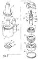
- a tapping attachment 10 is coupleable through a shank 12 to a source of rotational drive in the form of a driving machine (not shown).
- a stem 14 is disposed in and extends from a closure 15 positioned adjacent a housing 16 of the tapping attachment 10 and is connectable in conventional fashion to the driving machine to provide restraint against rotation of the housing 16 of tapping attachment 10 when connected to the driving machine and to permit rotation under particular circumstances when not so connected.
- Housing 16 defines a central bore 17 for receiving a drive spindle member 18.
- Drive spindle member 18 partially extends outwardly of housing 16. At its upper end, spindle member 18 extends into and is engaged with the member 12 for engagement with the driving machine.
- drive spindle member 18 includes a mount 20 having an insert 22, defining a central bore 24.
- Insert 22 includes a fitting 25 for holding and aligning a coolant tube 26 which is fastened at its lower end to a tap 28 and forms a conduit for passage of coolant therethrough for the purpose of cooling tap 28 and clearing debris in the form of cuttings and the like from the work piece.
- Tap 28 is carried on a tap spindle member 30 fastened to a spring member 32 by a cap 34 defining an eye (not shown) from which spring member 32 depends.
- Drive spindle member 18 at an upper portion thereof extends outwardly of housing 16 as noted above and comprises a lower end portion 34 within housing 16.
- Lower end portion 34 of drive spindle member 18 carries at least one spline 36 engageable with a bevel gear 40.
- Bevel gear 40 has in a preferred embodiment thirty-five (35) teeth, the bevel gear 40 being of the general type described and claimed in U.S. Patent No. 4,705,437.
- Bevel gear 40 comprises an upper gear 42 and a lower gear 44 and may be integral with drive spindle 18 or secured in housing 16.
- a planet gear carrier 46 is mounted in housing 16.
- a plurality of planet gears 48 are mounted in planet gear carrier 46 and in the preferred embodiment, have twelve (12) teeth. In particular applications in accordance with the invention planet gears may have a number of teeth other than twelve.
- Planet gears 48 are positioned to be engageable with bevel gear 40. Thus, rotation of drive spindle member 18 produces rotation of planet gears 48.
- a forward drive member 50 of generally annular configuration, defines a central bore 52.
- Drive member 50 carries on its radially inward wall at least one drive spline member 54.
- Forward drive member 50 is engageable with upper gear 42.
- First drive member 50 carries fittings 56 along its upper exterior periphery.
- Spline 54 on forward drive member 50 comprises a pair of symmetrical generally arcuate contact areas 55, joined by a generally arcuate intermediate region 57.
- a dampener member 60 of generally cylindrical configuration with a central bore 62 carries at least one peripheral fitting 64 and has defined at its periphery at least one slot 66 adjacent fitting 64. Dampener 60 is snugly fittable upon drive member by placing slot 66 and adjacent fitting 64 against drive member fittings 56 whereby the sides of slots 66 and fittings 64 engage opposite sides of fittings 56, in a snap fit, dampener 60 being preferably composed of resilient material such as neoprene.
- Drive member 50 defines at least one (shown in the depicted embodiment as three) upper peripheral splines 68 for engaging drive spindle 18.
- Forward drive member 50 includes at least one (shown as three in the depicted embodiment) inner slots 70 for receiving fittings 67 of driver member 50.
- peripheral slots 68 are generally rectangular with one edge shown as on the right, forming a leading edge on a clockwise rotation, having a somewhat convexly curved edge with a rounded upper portion 72.
- a reverse drive member 74 is engageable with lower gear 44.
- Second drive member 74 is identical in all respects with first drive member 50 and the parts are interchangeable with each other.
- a second dampener 76 fits on driver 74 in the same manner as dampener 60 with respect to drive member 50, and together with driver 74 and lower gear 44, forms an identical subassembly to the subassembly comprising driver 50, dampener 60 and upper gear 42, with the sole exception that lower gear 44 has thirty-seven (37) teeth as opposed to thirty-five (35) teeth for upper gear 42, thus resulting in slower rotation upon engagement with planet gears 48 to the end of reducing wear in the tapping attachment 10 as is fully described in U.S. Patent No. 4,705,437.
- the number of teeth on upper gear 42 and lower gear 44 may be other than as stated and the speed of rotation of the reverse and forward drive members may be substantially equal or may have any relationship at all, in accordance with the invention.
- a button head screw 78 fastenable into an access slot 79 in housing 16 provides closure of access slot 79.
- Three set screws 80 extend radially inward from three (3) points at the periphery of mount 20 and have hex-shaped end slots. Set screws 80 pass through a rotary member 81 and engage a slot 84 in a spindle bushing 86.
- a locking ring 88 is fastened to the lower end of housing 16 holding a base member 87 thereof in place and is removable as discussed hereinbelow in connection with disassembly of tapping attachment 10.
- a bearing 89 is disposed adjacent lower gear 44.
- coolant tube 26 aligns with tap 28 which contains channels (not shown) for passage therethrough of coolant from tube 26.
- a coolant conduit 92 provides for expulsion of unneeded coolant.
- a drive sleeve 100 within housing 16 is generally cylindrical having a central bore 102 and defines at its periphery at least two slots 104 for accommodation and movement therein of drive balls 108.
- Drive sleeve member 100 includes at least one drive spline 110 engageable with tap spindle member 30, which carries at least one drive pin 112.
- Slots 104 are of generally ellipsoidal configuration.
- Drive spline 110, drive pin 112 and slots 104 are in accordance with the disclosure and claims in U.S. Patent No. 5,209,616 assigned to the assignee hereof. As disclosed in detail in Patent No. 5,209,616 the configuration and relations of the above-described parts tend to minimize wear and shock in operation.
- a closure 114 fastened to housing 16 contains an access tool 116 removably secured in a threaded holding slot 118 defined in closure 114.
- Access tool 116 comprises a hex-head screwdriver 120 removably secured in and extending from an aperture 122 defined in access tool 116.
- Access tool 116 further comprises a key 124 removably secured to screwdriver 120.
- Stem 14 defines a slot 126 for receiving and movably securing an arm 128 held at its opposite end in a recess 130 defined in a movable collar 132 at the upper end of housing 16.
- Collar 132 is attached by means (not shown) to mount 20.
- a spring 134 in closure 15 biases stem 14 upwardly.
- a slot (not shown) in housing 16 is aligned with recess 130.
- a diagram 134 of tapping attachment 10 is inscribed on the periphery of housing 16 in conjunction with instructions 136 inscribed on closure 15 concerning disassembly of tapping attachment 10.
- the arrangement described in this section is generally in accordance with U.S. Patent No. 4,566,829 assigned to the assignee of the present application.
- rotation is transmitted from the driving machine to forward driver 50 and to reverse driver 74 through bevel gear 40 and planet gears 42,44, respectively.
- splines 56 on drive member 50 engage with splines 72 of gear 42, through balls 114, as depicted in Fig. 6.
- driver 50 and balls 114 experience less shock and wear than in existing devices.
- Driver sleeve 50 is rotated in the forward direction and as a result, drive splines 54 engage balls 108 on drive sleeve 100 which in turn causes engagement with drive pins 112 of spindle 30.
- Coolant is provided during tapping from the driving machine 12 via the conduit 26.
- the tapping attachment 10 is raised by the driving machine.
- the tap is embedded in the hole and removal is most conveniently accomplished by reversing the tap rotation.
- drive sleeve 100 travels upwardly until it engages reverse drive member 74, thereby causing reverse rotation of the spindle 30 and tap 28, enabling efficient withdrawal of the tap 20 from the hole.
- driving engagement is cushioned due to the configuration of slots 104, the presence of the dampener 76 and the shape of the edges of the drive splines on the reverse driver 74 identical to forward driver 50.
- a further significant advantage of the invention is its ready disassembleability and maintainability.
- a method for disassembling and reassembling tapping attachments in accordance with the invention is depicted in Fig. 7.
- access tool 116 is removed from closure 15 by being unscrewed therefrom by manual manipulation.
- Key 124 is then inserted into a slot 138 in locking ring 88, and given a counter-clockwise turn to loosen the locking ring 88.
- Screwdriver 120 is then detached from key 124. Screwdriver 120 is then employed to unfasten screw 78, exposing access slot 79. Screwdriver 120 is then placed into slot 79.
- Tapping attachment 10 is then manually supported generally with its longitudinal axis horizontal so that screwdriver 120 points sufficiently downward to be held therein by gravity.
- the user compresses stem 14 so that arm 126 is displaced from its restraining position in slot 130 thereby freeing collar 132 (and attached mount 20) to rotate.
- collar 132 is caused to rotate slightly until a set screw so rotates into alignment with the hex-head screwdriver 120, which then drops into the hex- shaped receptacle at the outer end of screws 80.
- routine maintenance and repair including lubrication may be performed upon tapping attachment 10.
- Forward drive member 50 and rear drive member 74 may be checked for wear.
- An additional advantage of the invention is that due to the nature of tapping (whereby forward drive is more wearing than reverse due to resistance of the workpiece), in most applications reverse drive members wear at approximately one-third the rate of forward drive members. Thus, when a worn forward drive member is taken out of service it may be replaced by a reverse drive member in much the same manner as worn front tires of an automobile may be replaced by less worn rear tires. This is attributable to the ready disassembleabilty feature of the invention together with the interchangeability of the forward and rear driver members.
- tapping attachments can be scheduled for periodic repair and maintenance in the same manner as other machinery such as automobiles.
- existing tapping devices lacking ready disassemblability and interchangability of parts, the tapping attachments are used until they break down, at which time they are sent out for repair or discarded.
- tapping attachments in accordance with the invention, and utilizing experience in tapping with particular work pieces and/or particular equipment, a reasonable approximation can be made as to the number of tapped holes which the driver elements will accomplish before exhibiting wear or breakdown.
- the equipment can be quickly disassembled, checked, maintained, and worn elements replaced, if necessary. This avoids the tendency to use-to-breakdown which characterizes operations with existing tapping attachments.
Landscapes
- Engineering & Computer Science (AREA)
- Mechanical Engineering (AREA)
- Jigs For Machine Tools (AREA)
- Automatic Assembly (AREA)
Claims (27)
- Accessoire de taraudage auto-inversant (10) comportant :lesdits moyens formant broche pour taraud (18) étant mobiles en va-et-vient le long de la direction de taraudage par rapport audit élément entraíneur vers l'avant (50) et audit élément entraíneur vers l'arrière (74), ledit élément entraíneur vers l'avant (50) et ledit élément entraíneur vers l'arrière (74) étant interchangeables l'un avec l'autre.(a) des moyens formant broche pour taraud (18) pour maintenir un taraud (28) et pouvant tourner pour accomplir un taraudage,(b) des moyens d'entraínement vers l'avant ayant la forme d'un élément entraíneur vers l'avant (50) pouvant coopérer avec lesdits moyens formant broche pour taraud (18) pour imprimer une rotation audit élément formant broche pour taraud (18) afin d'accomplir un taraudage,(c) des moyens d'entraínement vers l'arrière ayant la forme d'un élément d'entraínement vers l'arrière (74) pouvant coopérer avec lesdits moyens formant broche pour taraud (18) pour imprimer une rotation auxdits moyens formant broche pour taraud (18) dans un direction opposée à la rotation imprimée par ledit élément entraíneur vers l'avant (50),(d) des moyens d'engrenage (42, 44) pour transmettre un entraínement audit élément entraíneur vers l'avant (50) et audit élément entraíneur vers l'arrière (74),
- Accessoire de taraudage selon la revendication 1, comportant de plus des moyens amortisseurs (60) pouvant coopérer avec lesdits moyens d'entraínement vers l'avant ayant la forme dudit élément entraíneur vers l'avant (50).
- Accessoire de taraudage selon la revendication 1, comportant de plus des moyens amortisseurs (76) pouvant coopérer avec lesdits moyens d'entraínement vers l'arrière ayant la forme dudit élément entraíneur vers l'arrière (74).
- Accessoire de taraudage selon la revendication 1, dans lequel lesdits moyens d'engrenage (42, 44) produisent pratiquement une rotation simultanée desdits moyens d'entraínement vers l'avant ayant la forme dudit élément entraíneur vers l'avant (50), et desdits moyens d'entraínement vers l'arrière ayant la forme dudit élément entraíneur vers l'arrière (74) à des vitesses différentes.
- Accessoire de taraudage selon la revendication 4, dans lequel lesdits moyens d'entraínement vers l'avant ayant la forme dudit élément entraíneur vers l'avant (50) produisent une rotation à vitesse plus grande que la vitesse de rotation produite par lesdits moyens d'entraínement vers l'arrière ayant la forme dudit élément entraíneur vers l'arrière (74).
- Accessoire de taraudage selon la revendication 1, dans lequel lesdits moyens d'engrenage (42, 44) produisent pratiquement une rotation simultanée desdits moyens d'entraínement vers l'avant ayant la forme dudit élément entraíneur vers l'avant (50), et desdits moyens d'entraínement vers l'arrière ayant la forme dudit élément entraíneur vers l'arrière (74) à des vitesses sensiblement égales.
- Accessoire de taraudage selon la revendication 1, comportant de plus un élément formant boítier (16) contenant lesdits moyens formant broche pour taraud (18), lesdits moyens d'entraínement vers l'avant ayant la forme dudit élément entraíneur vers l'avant (50), lesdits moyens d'entraínement vers l'arrière ayant la forme dudit élément entraíneur vers l'arrière (74) et lesdits moyens d'engrenage (42, 44), et comportant de plus des premiers moyens de fixation pouvant être démontés et des seconds moyens de fixation pouvant être démontés, lesdits premiers moyens de fixation pouvant être démontés étant montés de manière amovible sur ledit boítier (16) et lesdits seconds moyens de fixation étant montés à l'intérieur dudit élément formant boítier (16) et accessibles à partir de l'extérieur dudit élément formant boítier (16), lesdits premiers moyens de fixation pouvant être démontés et lesdits seconds moyens de fixation pouvant être démontés pouvant coopérer avec lesdits moyens contenus dans le boítier (16) de telle sorte que lors du démontage desdits premiers moyens de fixation pouvant être démontés et desdits seconds moyens de fixation pouvant être démontés, lesdits moyens contenus peuvent être enlevés dudit boítier (16).
- Accessoire de taraudage selon la revendication 1, comportant de plus des moyens amortisseurs (60) portés par lesdits moyens d'entraínement vers l'avant ayant la forme dudit élément entraíneur vers l'avant (50) afin de réduire l'usure de celui-ci pendant un fonctionnement.
- Accessoire de taraudage selon la revendication 1, comportant de plus des moyens (76) portés par lesdits moyens d'entraínement vers l'arrière ayant la forme dudit élément entraíneur vers l'arrière (74) afin de réduire l'usure de celui-ci pendant un fonctionnement.
- Accessoire de taraudage selon la revendication 1, dans lequel lesdits moyens d'engrenage (42) comportent des moyens de coopération avec lesdits moyens d'entraínement vers l'avant ayant la forme dudit élément entraíneur vers l'avant (50) dans une coopération d'entraínement, et configurés pour amortir le choc lors d'une telle coopération.
- Accessoire de taraudage selon la revendication 1, dans lequel lesdits moyens d'engrenage (44) comportent des moyens pour coopérer avec lesdits moyens d'entraínement vers l'arrière ayant la forme dudit élément entraíneur vers l'arrière (74) dans une coopération d'entraínement, et configurés pour amortir le choc lors d'une telle coopération.
- Accessoire de taraudage selon la revendication 1, comportant de plus des moyens formant manchon d'entraínement (100) pour coopérer avec lesdits moyens formant broche pour taraud (18) afin d'imprimer une rotation à ceux-ci, et pouvant se déplacer pour coopérer avec lesdits moyens d'entraínement vers l'avant ayant la forme dudit élément entraíneur vers l'avant (50), et avec lesdits moyens d'entraínement vers l'arrière ayant la forme dudit élément entraíneur vers l'arrière (74) à entraíner de la sorte, lesdits moyens formant manchon d'entraínement (100) comportant des moyens pour amortir le choc dû au heurt avec lesdits moyens d'entraínement vers l'avant ayant la forme dudit élément entraíneur vers l'avant (50), lesdits moyens d'entraínement vers l'arrière ayant la forme dudit élément entraíneur vers l'arrière (74) et desdits moyens formant broche pour taraud (18).
- Accessoire de taraudage selon la revendication 12, dans lequel lesdits moyens formant broche pour taraud (18) comportent des moyens pour coopérer en coopération d'entraínement avec lesdits moyens formant manchon d'entraínement (100), lesdits moyens étant configurés pour réduire le choc lors d'une coopération entre lesdits moyens formant manchon d'entraínement (100) et lesdits moyens formant broche pour taraud (18).
- Accessoire de taraudage selon la revendication 1, comportant de plus un élément formant outil (116) pouvant être stocké dans ledit accessoire de taraudage (10) pour démonter ledit accessoire de taraudage (10).
- Accessoire de taraudage selon la revendication 7, dans lequel lesdits seconds moyens de fixation comportent un élément de base (87) comportant des moyens (88) pour fixer ledit élément de base (87) audit élément formant boítier (16).
- Accessoire de taraudage selon la revendication 7, dans lequel lesdits seconds moyens de fixation comportent au moins une vis sans tête (80) maintenant ledit élément formant broche de maintien de taraud (18) dans ledit boítier (16).
- Accessoire de taraudage selon la revendication 7, dans lequel ledit élément d'entraínement vers l'avant (50) et ledit élément d'entraínement vers l'arrière (74) sont pratiquement identiques.
- Accessoire de taraudage selon la revendication 16, dans lequel ledit élément formant boítier (16) définit une ouverture d'accès (79) pour accéder à ladite au moins une vis sans tête (80), et comportant de plus des moyens mobiles (81) définissant au moins une ouverture, lesdits moyens mobiles (81) étant mobiles pour aligner ladite au moins une ouverture avec ladite au moins une vis sans tête (80) et avec ladite ouverture d'accès (79), afin de donner accès à partir de l'extérieur dudit élément formant boítier (16) à ladite au moins une vis sans tête (80).
- Accessoire de taraudage selon la revendication 18, dans lequel ledit élément de base (87) comporte des moyens de coopération avec un outil d'accès pour coopérer avec un outil d'accès (116) afin de desserrer et serrer ledit élément de base (87), et comportant de plus un élément formant outil d'accès (116, 124, 120) pour coopérer avec lesdits moyens de coopération avec un outil d'accès dudit élément de base (87) afin de desserrer et serrer ledit élément de base (87) et pour coopérer avec ladite au moins une vis sans tête (80) afin de desserrer et serrer ladite au moins une vis sans tête (80).
- Accessoire de taraudage selon la revendication 19, dans lequel ledit élément formant outil d'accès (116) peut être stocké dans ledit accessoire de taraudage (10).
- Accessoire de taraudage selon la revendication 18, dans lequel lesdits moyens de coopération avec un outil d'accès situés dans ledit élément de base (87) comportent une fente (138), et dans lequel ledit élément formant outil d'accès (116) comporte un élément séparé (124) destiné à coopérer avec ladite fente (138) dudit élément de base (87), et un élément formant tournevis séparé (120) destiné à coopérer avec ladite au moins une vis sans tête (80).
- Accessoire de taraudage selon la revendication 21, dans lequel ledit élément formant tournevis (120) dudit élément formant outil d'accès (116) peut être fixé afin d'être stocké dans ledit élément (124) destiné à coopérer avec ladite fente (138) dudit élément de base (87).
- Accessoire de taraudage selon la revendication 18, comportant de plus un élément de commande (14) pour commander le déplacement desdits moyens d'accès rotatifs, ledit élément de commande étant mobile entre une première position dans laquelle ledit élément formant boítier (16) n'est pas libre de tourner, et une seconde position dans lequel ledit boítier (16) est libre de tourner.
- Accessoire de taraudage selon la revendication 7, dans lequel des instructions (134) pour démonter ledit accessoire de taraudage (10) sont représentées sur l'extérieur dudit accessoire de taraudage (10).
- Procédé pour démonter un accessoire de taraudage (10) selon les revendications 1 à 24, ayant un boítier (16) muni d'un élément de base pouvant être démonté (87) et de moyens de fixation intérieurs (132) pour retenir un élément formant broche de maintien de taraud (18) comportant les étapes consistant à :(a) desserrer ledit élément de base (87),(b) supprimer la fixation desdits moyens de fixation intérieurs (132),(c) enlever ledit élément de base (87),(d) retirer ladite broche de maintien de taraud (18) dudit élément formant boítier (16).
- Procédé selon la revendication 25, dans lequel ledit accessoire de taraudage (10) comporte des moyens d'accès intérieurs fournissant un accès extérieur auxdits moyens de fixation intérieurs (132), et des moyens de commande extérieurs (14) pouvant être manipulés pour commander lesdits moyens d'accès intérieurs, dans lequel l'étape de suppression de la fixation desdits moyens de fixation intérieurs (132) comporte l'étape de manipulation desdits moyens de commande extérieurs (14) pour amener lesdits moyens d'accès intérieurs à fournir un accès auxdits moyens de fixation intérieurs (132).
- Procédé selon la revendication 25, comportant de plus l'étape de programmation dudit accessoire de taraudage (10) pour un démontage pour réparation et entretien périodique selon le nombre de trous taraudés effectués par ledit accessoire de taraudage (10).
Applications Claiming Priority (2)
| Application Number | Priority Date | Filing Date | Title |
|---|---|---|---|
| US218257 | 1994-03-28 | ||
| US08/218,257 US5628593A (en) | 1994-03-28 | 1994-03-28 | Readily disassembleable tapping attachment with quick change replaceable and maintainable parts and method |
Publications (2)
| Publication Number | Publication Date |
|---|---|
| EP0677351A1 EP0677351A1 (fr) | 1995-10-18 |
| EP0677351B1 true EP0677351B1 (fr) | 2001-02-07 |
Family
ID=22814388
Family Applications (1)
| Application Number | Title | Priority Date | Filing Date |
|---|---|---|---|
| EP95301966A Expired - Lifetime EP0677351B1 (fr) | 1994-03-28 | 1995-03-24 | Appareil de taraudage facilement démontable avec des parts à changement rapide et à entretien facile et méthode de fabrication |
Country Status (3)
| Country | Link |
|---|---|
| US (1) | US5628593A (fr) |
| EP (1) | EP0677351B1 (fr) |
| DE (1) | DE69520057T2 (fr) |
Families Citing this family (6)
| Publication number | Priority date | Publication date | Assignee | Title |
|---|---|---|---|---|
| CN1086970C (zh) * | 1996-11-18 | 2002-07-03 | 卢才美 | 攻丝装置的正反转换向机构 |
| EP0980734A1 (fr) * | 1998-08-20 | 2000-02-23 | Tapmatic Corporation | Appareil de filetage auto-renversement avec absorption de choc |
| US8162573B2 (en) * | 2004-09-07 | 2012-04-24 | The Tapmatic Corporation | Self-reversing tapping system |
| JP2006088270A (ja) * | 2004-09-24 | 2006-04-06 | Makino J Kk | 工作機械の主軸アタッチメント装置 |
| US7708506B2 (en) * | 2005-06-16 | 2010-05-04 | The Tapmatic Corporation | Self-synchronizing tap driver for rigid tapping with starting force adjustment |
| US20100232894A1 (en) * | 2009-03-16 | 2010-09-16 | The Boeing Company | Adaptor with Interchangeable Load Sensing Elements |
Family Cites Families (13)
| Publication number | Priority date | Publication date | Assignee | Title |
|---|---|---|---|---|
| US2941414A (en) * | 1954-03-30 | 1960-06-21 | Lee Engineering Company | Friction clutch mechanism |
| US3717892A (en) * | 1970-04-09 | 1973-02-27 | Tapmatic Corp | Tapping attachment for numerical control |
| US3946844A (en) * | 1974-09-23 | 1976-03-30 | Tapmatic Corporation | Clutching means adapted for tapping attachments |
| US3999642A (en) * | 1974-09-23 | 1976-12-28 | Tapmatic Corporation | Clutching means adapted for use in tapping attachments |
| US4014421A (en) * | 1974-11-04 | 1977-03-29 | Tapmatic Corporation | Clutching means adapted for use in tapping attachments |
| US4123192A (en) * | 1977-10-11 | 1978-10-31 | Ruland Frederick W | Tapping attachment for a machine tool |
| US4277209A (en) * | 1979-12-03 | 1981-07-07 | Erickson Tool Company | Threading attachment |
| US4566829A (en) * | 1985-02-04 | 1986-01-28 | Tapmatic Corporation | Tapping attachment and indexing mechanism therefor |
| US4705437A (en) * | 1985-02-04 | 1987-11-10 | Tapmatic Corporation | Reversible dual speed tapping attachment |
| US4832542A (en) * | 1987-04-08 | 1989-05-23 | Tapmatic Corporation | Clutching means adapted for tapping attachment |
| US5203651A (en) * | 1989-03-30 | 1993-04-20 | Tapmatic Corporation | Tapping attachments |
| US5209616A (en) * | 1991-06-27 | 1993-05-11 | Tapmatic Corporation | Drive in tapping attachments |
| US5213453A (en) * | 1991-06-28 | 1993-05-25 | Tapmatic Corporation | Cooling systems in tapping attachments suitable for high pressure applications |
-
1994
- 1994-03-28 US US08/218,257 patent/US5628593A/en not_active Expired - Fee Related
-
1995
- 1995-03-24 DE DE69520057T patent/DE69520057T2/de not_active Expired - Fee Related
- 1995-03-24 EP EP95301966A patent/EP0677351B1/fr not_active Expired - Lifetime
Also Published As
| Publication number | Publication date |
|---|---|
| DE69520057T2 (de) | 2001-05-23 |
| EP0677351A1 (fr) | 1995-10-18 |
| DE69520057D1 (de) | 2001-03-15 |
| US5628593A (en) | 1997-05-13 |
Similar Documents
| Publication | Publication Date | Title |
|---|---|---|
| CA2657895C (fr) | Dispositif de maintien de taraud | |
| USRE33335E (en) | Device for attaching a tool | |
| US5639273A (en) | Grinding cup and holder device | |
| US6394711B1 (en) | Rotary cutting tool and holder therefor | |
| US20040004329A1 (en) | Quick change chuck | |
| CN101508030B (zh) | 自动锁闭卡盘 | |
| EP0250703A2 (fr) | Allongement pour des outils à fileter, muni d'un système de refroidissement | |
| EP0677351B1 (fr) | Appareil de taraudage facilement démontable avec des parts à changement rapide et à entretien facile et méthode de fabrication | |
| EP1066902A2 (fr) | Accouplement pour scie-cloche | |
| CA1312421C (fr) | Machine portative a dresser et a tarauder equipee de moyens interchangeables de determination de la conicite | |
| EP1671728B1 (fr) | Porte-outil de tourelle | |
| US4767246A (en) | Quick-release tool holding device | |
| RU2028878C1 (ru) | Державка для установки закрепления инструмента | |
| JP3777129B2 (ja) | マシニングセンター用の手動操作可能な工具ホルダー | |
| US5527206A (en) | Holder device | |
| US5865575A (en) | Self-reversing tapping attachment with shock absorption | |
| RU2179106C2 (ru) | Шлифовальная насадка и держатель | |
| MXPA97005952A (en) | Tripuration vessel and retene device | |
| EP0659511B1 (fr) | Système d'outil | |
| JPS59224226A (ja) | 工具ホルダ着脱保持装置 | |
| CN118124029B (zh) | 一种石英加工刀具快拆装置 | |
| KR102744295B1 (ko) | 14cm 협소공간에서의 CNC 복합기용 절삭공구 한손 떨굼받음형 교체 형성장치 및 방법 | |
| KR910007234B1 (ko) | 공구자동 교환장치 | |
| JP3127357U (ja) | ツールホルダ | |
| GB2215246A (en) | Boring tool |
Legal Events
| Date | Code | Title | Description |
|---|---|---|---|
| PUAI | Public reference made under article 153(3) epc to a published international application that has entered the european phase |
Free format text: ORIGINAL CODE: 0009012 |
|
| AK | Designated contracting states |
Kind code of ref document: A1 Designated state(s): DE FR GB IT |
|
| 17P | Request for examination filed |
Effective date: 19960409 |
|
| 17Q | First examination report despatched |
Effective date: 19980731 |
|
| GRAG | Despatch of communication of intention to grant |
Free format text: ORIGINAL CODE: EPIDOS AGRA |
|
| GRAG | Despatch of communication of intention to grant |
Free format text: ORIGINAL CODE: EPIDOS AGRA |
|
| GRAG | Despatch of communication of intention to grant |
Free format text: ORIGINAL CODE: EPIDOS AGRA |
|
| GRAH | Despatch of communication of intention to grant a patent |
Free format text: ORIGINAL CODE: EPIDOS IGRA |
|
| GRAH | Despatch of communication of intention to grant a patent |
Free format text: ORIGINAL CODE: EPIDOS IGRA |
|
| GRAA | (expected) grant |
Free format text: ORIGINAL CODE: 0009210 |
|
| AK | Designated contracting states |
Kind code of ref document: B1 Designated state(s): DE FR GB IT |
|
| PG25 | Lapsed in a contracting state [announced via postgrant information from national office to epo] |
Ref country code: IT Free format text: LAPSE BECAUSE OF FAILURE TO SUBMIT A TRANSLATION OF THE DESCRIPTION OR TO PAY THE FEE WITHIN THE PRESCRIBED TIME-LIMIT;WARNING: LAPSES OF ITALIAN PATENTS WITH EFFECTIVE DATE BEFORE 2007 MAY HAVE OCCURRED AT ANY TIME BEFORE 2007. THE CORRECT EFFECTIVE DATE MAY BE DIFFERENT FROM THE ONE RECORDED. Effective date: 20010207 Ref country code: FR Free format text: LAPSE BECAUSE OF FAILURE TO SUBMIT A TRANSLATION OF THE DESCRIPTION OR TO PAY THE FEE WITHIN THE PRESCRIBED TIME-LIMIT Effective date: 20010207 |
|
| REF | Corresponds to: |
Ref document number: 69520057 Country of ref document: DE Date of ref document: 20010315 |
|
| EN | Fr: translation not filed | ||
| PLBE | No opposition filed within time limit |
Free format text: ORIGINAL CODE: 0009261 |
|
| STAA | Information on the status of an ep patent application or granted ep patent |
Free format text: STATUS: NO OPPOSITION FILED WITHIN TIME LIMIT |
|
| REG | Reference to a national code |
Ref country code: GB Ref legal event code: IF02 |
|
| 26N | No opposition filed | ||
| PGFP | Annual fee paid to national office [announced via postgrant information from national office to epo] |
Ref country code: DE Payment date: 20060316 Year of fee payment: 12 |
|
| PGFP | Annual fee paid to national office [announced via postgrant information from national office to epo] |
Ref country code: GB Payment date: 20060322 Year of fee payment: 12 |
|
| GBPC | Gb: european patent ceased through non-payment of renewal fee |
Effective date: 20070324 |
|
| PG25 | Lapsed in a contracting state [announced via postgrant information from national office to epo] |
Ref country code: DE Free format text: LAPSE BECAUSE OF NON-PAYMENT OF DUE FEES Effective date: 20071002 |
|
| PG25 | Lapsed in a contracting state [announced via postgrant information from national office to epo] |
Ref country code: GB Free format text: LAPSE BECAUSE OF NON-PAYMENT OF DUE FEES Effective date: 20070324 |