EP0677455A1 - Kleinbehälter - Google Patents
Kleinbehälter Download PDFInfo
- Publication number
- EP0677455A1 EP0677455A1 EP95105529A EP95105529A EP0677455A1 EP 0677455 A1 EP0677455 A1 EP 0677455A1 EP 95105529 A EP95105529 A EP 95105529A EP 95105529 A EP95105529 A EP 95105529A EP 0677455 A1 EP0677455 A1 EP 0677455A1
- Authority
- EP
- European Patent Office
- Prior art keywords
- small container
- small
- plug connection
- elevations
- container according
- Prior art date
- Legal status (The legal status is an assumption and is not a legal conclusion. Google has not performed a legal analysis and makes no representation as to the accuracy of the status listed.)
- Granted
Links
- 239000013013 elastic material Substances 0.000 claims abstract description 3
- 238000005096 rolling process Methods 0.000 claims description 19
- 230000008878 coupling Effects 0.000 claims description 12
- 238000010168 coupling process Methods 0.000 claims description 12
- 238000005859 coupling reaction Methods 0.000 claims description 12
- 230000002093 peripheral effect Effects 0.000 claims description 6
- 238000003780 insertion Methods 0.000 abstract description 6
- 230000037431 insertion Effects 0.000 abstract description 6
- 230000000717 retained effect Effects 0.000 abstract 1
- 230000003068 static effect Effects 0.000 description 7
- 239000011324 bead Substances 0.000 description 5
- 238000013461 design Methods 0.000 description 4
- 238000000034 method Methods 0.000 description 4
- 239000004033 plastic Substances 0.000 description 3
- 230000005489 elastic deformation Effects 0.000 description 2
- 239000004743 Polypropylene Substances 0.000 description 1
- 235000019219 chocolate Nutrition 0.000 description 1
- 238000010276 construction Methods 0.000 description 1
- 238000011161 development Methods 0.000 description 1
- 230000018109 developmental process Effects 0.000 description 1
- 235000013601 eggs Nutrition 0.000 description 1
- 238000009434 installation Methods 0.000 description 1
- 238000012986 modification Methods 0.000 description 1
- 230000004048 modification Effects 0.000 description 1
- 239000002991 molded plastic Substances 0.000 description 1
- 239000005022 packaging material Substances 0.000 description 1
- 238000004806 packaging method and process Methods 0.000 description 1
- -1 polypropylene Polymers 0.000 description 1
- 229920001155 polypropylene Polymers 0.000 description 1
- 238000012549 training Methods 0.000 description 1
Images


Classifications
-
- B—PERFORMING OPERATIONS; TRANSPORTING
- B65—CONVEYING; PACKING; STORING; HANDLING THIN OR FILAMENTARY MATERIAL
- B65D—CONTAINERS FOR STORAGE OR TRANSPORT OF ARTICLES OR MATERIALS, e.g. BAGS, BARRELS, BOTTLES, BOXES, CANS, CARTONS, CRATES, DRUMS, JARS, TANKS, HOPPERS, FORWARDING CONTAINERS; ACCESSORIES, CLOSURES, OR FITTINGS THEREFOR; PACKAGING ELEMENTS; PACKAGES
- B65D81/00—Containers, packaging elements, or packages, for contents presenting particular transport or storage problems, or adapted to be used for non-packaging purposes after removal of contents
- B65D81/36—Containers, packaging elements, or packages, for contents presenting particular transport or storage problems, or adapted to be used for non-packaging purposes after removal of contents adapted to be used for non-packaging purposes after removal of contents
- B65D81/361—Modular elements with complementary shapes, interengageable parts or the like
Definitions
- the present invention relates to a small container, in particular made of plastic, with at least one cylindrical, in particular circular-cylindrical section, with a device located in the region of the cylindrical circumferential surface of this section for producing a form-fitting slide-plug connection with at least one further such small container.
- Such a small container is known from DE-OS 41 19 252.
- the small container described there has a molded plastic body with an upper and a lower part and can accommodate various objects. The top and bottom are separable.
- the device for producing a positive sliding-plug connection of this small container consists of a plurality of dovetail-shaped recesses and elevations on the circumference of the small container, so that several such small containers can be rigidly plugged together with this plug-in or sliding connection option.
- the small container can be used as a plug-in component of a plug-in modular toy.
- Small containers of this type are used, for example, as contents of hollow bodies, such as chocolate eggs, and take up in them Function as packaging material such as toy parts as a surprise item.
- a toy in the form of a plug-in module, several small containers can be put together in a variety of combinations, but only one static structure is the result.
- these purely static combinations of small containers are not sufficient for use as an interesting and versatile toy.
- the invention is therefore based on the technical problem of improving a generic small container in a simple and effective manner in such a way that both a large number of static and movable combination options exist and the small container can be used in a variety of ways as a toy.
- a small container in particular made of plastic, with at least one cylindrical, in particular circular-cylindrical section, with a device located in the region of the cylindrical peripheral surface of this section for producing a form-fitting push-plug connection with at least one further such small container, which thereby is characterized in that the small container with its device for producing the push-plug connection perpendicular to the plug direction on a similarly designed device of another such small container can be rolled in the circumferential direction and is always held positively in the radial direction.
- the advantage of the small container according to the invention lies not only in the fact that several such small containers can be combined statically in various directions or dimensions, so that diverse shapes and constructions can be formed, a stable and releasable connection between several small containers being made possible will, but also in the fact that stable movable structures can be created at the same time, so that the possible uses are increased and the value of play and amusement is increased.
- the device for producing a push-plug connection comprises alternating, coordinated recesses and elevations on a region of the cylindrical peripheral surface of the small container, which form-fitting sliding plug Connection can be established by engaging at least one elevation in a recess, and the elevations and recesses are designed and their divisions and distances to one another are selected and coordinated with one another such that when two small containers roll off, the elevation leading in the unwinding direction already engages in positive engagement with the next recess is before the elevation lagging in the rolling direction and currently in engagement with a recess is released from the final engagement.
- a coupling element is provided on at least one end face of the small container for establishing a releasable connection with at least one further such small container.
- a coupling element has proven to be particularly suitable, which is a bayonet-like component or another suitable plug connection or the like.
- a stop is provided on the small container and / or on the device for producing the slide-plug connection, so that a slide-plug connection can only be produced from one direction of insertion.
- the push-plug connection can easily be held by the frictional forces occurring on the device for producing this connection, it is possible for larger small containers according to the invention that the push-plug connection is released in a corresponding position of the small containers is because a small container overcomes the frictional forces due to its heavy weight and slips out of engagement. This is effectively prevented by the design measure described above.
- the small containers 2 are constructed essentially cylindrical and have rounded ends at the end of the long side, which merge into flattened end sections.
- the lateral surfaces of the small containers 2 are cylindrical.
- a coupling element 14 is provided in each case for establishing a releasable connection with at least one further small container 2, so that the small containers can be connected with their respective end sections opposite one another.
- the small container 2 has a circular cylindrical section 8, the diameter of which in the present case is slightly larger than the diameter of the small container 2 itself. However, this measure is not mandatory and the diameter of the circular cylindrical section 8 can also assume the diameter of the small container 2.
- a device 16, 18 for producing a form-fitting slide-plug connection with at least one further such small container 2 is arranged.
- the device 16, 18 for producing a positive sliding plug connection is arranged continuously around the entire circumference of the cylindrical section 8 or the small container 2.
- the device 16, 18 it is equally conceivable to design the device 16, 18 only on a partial area of the cylindrical section 8 or of the small container 2.
- the installation of a device for area-wise restriction of the Rolling movement of two small containers 2 put together is conceivable. This can be a stop, for example.
- the small container 2 has a lid-shaped upper part 4 and a lower part 6.
- the lower part 6 has a retracted edge over which the upper part 4 is slipped.
- the retracted edge is provided with a bead 10 for locking.
- Matching the bead 10 the upper part 4 has a groove 12.
- the annular bead 10 engages in the annular groove 12, so that a locking is achieved.
- the coupling element 14 on the lower part 6 of the small container 2 in the present case consists of a projection which consists of a hook element arranged on a circle with radially inwardly directed hook ends.
- the hook elements enclose a recess.
- a stop can be provided at the end of the connection position.
- a further embodiment of the coupling element 14 can be designed, for example, in such a way that projections which are matched to one another are in turn provided on the end sections of the small container 2.
- a protrusion is provided in the upper part 4, which has a button-like bulge in the end section.
- the lower part 6, on the other hand, has a projection which consists of an edge or ring with a circular recess which is larger than the projection of the upper part.
- the upper part 4 can be so put the lower part 6 together.
- any other suitable plug connections can also be used, including plug connections of the same design for the upper part 4 and lower part 6.
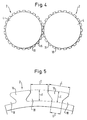
- Fig. 4 the principle of the static engagement of the device 16, 18 for producing a positive sliding plug connection of two small containers 2 is illustrated in a plan view. From the drawing it can be seen that the device for producing a push-plug connection consists of elevations 16 and recesses 18 which alternate on the circular cylindrical section 8 of the small container 2 and which extend continuously around the entire circumference of the circular cylindrical section 8 or of the small container 2 are arranged around.
- the elevations 16 and the recesses 18 are each dovetail-shaped.
- Fig. 5 shows the elevations 16 and recesses 18 in more detail.
- the dimensions of the elevations 16 and recesses 18 on which the present exemplary embodiment is based and the most important dimensions of the small container 2 (see also FIG. 1) are listed in Table 1 below: Table 1 Dimensions (mm): A 11.5 B 32 C. 02.9 D 02.5 E 01.0 F 01.0 G 01.8 H 45
- A denotes the length of the device 16, 18 for producing a sliding plug connection in its extent on the circular cylindrical section 8
- B the width of the small container 2
- C the width of the elevation 16 on the circumferential side
- D the width the recess 18 on the circumferential side
- E the height of the elevation 16 above the bottom of the recess 18,
- F the depth of the recess 18 relative to the upper edge of the elevation 16 on the circumferential side
- G the base width of the elevation 16 and H the height of the small container 2.
- the small container 2 according to the invention with the elevations 16 and recesses 18 is made entirely of plastic, such as polypropylene or ABS.
- the wall thickness of the small container 2 is approximately 0.5 to 1.0 mm in the present case. In the area of the circular cylindrical section 8 and the coupling elements 14, the wall thickness is preferably made thicker. Depending on the size of the small container, the dimensions can deviate significantly from the stated values.
- the small container 2 with its, the device for producing a push-plug connection, in the region of the cylindrical circumferential surface of the circular cylindrical section 8 alternately arranged and coordinated elevations 16 and recesses 18 is designed so that the positive push-plug connection Intervention of at least one elevation 16 can be produced in a recess 18, and the elevations 16 and recess 18 are designed and their divisions and distances to one another are selected and coordinated with one another such that when two such small containers roll, the elevation 16 leading in the unrolling direction is already one behind the other is in positive engagement with the next recess 18, before the elevation 16 lagging in the unwinding direction and currently in engagement with a recess 18 is released from the positive engagement.
- FIG. 6 shows the two small containers 2.1 and 2.2 in a static positive sliding plug connection.
- a single elevation 16.1b of the small container 2.1 engages in a single recess 18.2a of the small container 2.2.
- the elevations 16.2a, 16.2b of the small container 2.2 arranged on both sides of the recess 16.1b of the small container 2.1 are in such a position that their edges 20.2a and 22.2b enclose the elevation 16.1b of the small container 2.1, while the edges 20.2b and 22.2a slightly overlap the respective edges 20.1a and 22.1c of the elevations 16.1a and 16.1c located to the side of the engaging elevation 16.1b. With this overlap the edges mentioned may touch or be positioned at a small distance from one another.
- FIG. 7 shows a phase in which, starting from the static state shown in FIG. 6, a rolling movement is initiated perpendicular to the plugging direction and in the circumferential direction of the small containers 2.1, 2.2.
- the rolling direction is indicated by an arrow.
- the small container 2.1 is fixed, while the small container 2.2 is rolled out on the small container 2.1.
- the elevation 16.1b of the small container 2.1 which engages with the cutout 18.2a of the small container 2.2 is deformed slightly elastically and slightly bent in the rolling direction.
- the edge 20.2a of the elevation 16.2b currently lagging in engagement with the recess 18.2a migrates further upward to the edge 22.1b in the rolling direction, but remains in the form-fitting engagement.
- the elevation 16.2b leading in the unrolling direction moves to the left in the unrolling direction, so that its edge 20.2b comes to rest on the edge 22.1c of the elevation 16.1c.
- FIG. 8 shows a phase that follows the state shown in FIG. 7.
- the direction of roll is again indicated by an arrow.
- the edge 20.2b slides over the edge 22.1c, slips into the cutout 18.1b of the small container 2.1. and snaps in there.
- An elastic deformation of the elevation 16.2b can occur during this process. Due to the elastic deformation of the elevation 16.1b, elevation 16.2a of the small container 2.2 is still in positive engagement with this elevation 16.1b.
- the process described above is repeated for subsequent steps of the rolling movement.
- the rolling movement can take place both in the direction of the arrow shown in the figures and in the opposite direction.
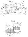
- FIG. 9 shows a second embodiment of a small container 2 according to the invention.
- 8 is at the end of the circular cylindrical section which is arranged the device 16, 18 for producing a positive sliding plug connection, provided with a stop 24 in the form of an annular shoulder, so that a sliding plug connection can only be made from one direction of insertion.
- a further small container combined with such a modified small container cannot slip out of the push-plug connection in the direction of the stop, a danger which exists in particular in the case of larger small containers according to the invention.
- a widening of the elevation 16 or a narrowing of the cutout 18 or another suitable measure can also serve as a stop.
- the present invention is not limited to the two embodiments described above. Changes and modifications are possible in a variety of ways.
- the small container can have a rectangular, cuboid or other polygonal shape, with a circular cylindrical section being provided for the device 16, 18 for producing a positive sliding plug connection within the given shape.
- Said device with its elevations 16 and recesses 18 can also be provided on the entire circumference of the small container 2 or can only be limited to certain areas.
- the elevations 16 and recesses 18 can also take other suitable shapes than the dovetail configuration described, e.g. asymmetrical training should also be considered.
- the small container according to the invention can have separate parts or additional parts which can be stored in the small container interior and which can be used in a suitable manner with the small container for use as a plug-in component of a plug-in modular toy are usable.
- the small container according to the invention can have additional plug-in connection options for slide or plug-in connections in several dimensions.
Landscapes
- Engineering & Computer Science (AREA)
- Mechanical Engineering (AREA)
- Packages (AREA)
- Stackable Containers (AREA)
- Closures For Containers (AREA)
- Steering Devices For Bicycles And Motorcycles (AREA)
- Nuclear Medicine (AREA)
- Details Of Rigid Or Semi-Rigid Containers (AREA)
- Control And Other Processes For Unpacking Of Materials (AREA)
- Cookers (AREA)
- Toys (AREA)
- Rigid Containers With Two Or More Constituent Elements (AREA)
Abstract
Description
- Die vorliegende Erfindung bezieht sich auf einen Kleinbehälter, insbesondere aus Kunststoff, mit zumindest einem zylindrischen, insbesondere kreiszylindrischen Abschnitt, mit einer im Bereich der zylindrischen Umfangsfläche dieses Abschnittes befindlichen Einrichtung zur Herstellung einer formschlüssigen Schiebe-Steck-Verbindung mit mindestens einem Weiteren solchen Kleinbehälter.
- Ein derartiger Kleinbehälter ist aus der DE-OS 41 19 252 bekannt. Der dort beschriebene Kleinbehälter weist einen Kunststoff-Formkörper mit einem Ober- und einem Unterteil auf und kann Verschiedene Gegenstände aufnehmen. Ober- und Unterteil sind trennbar. Die Einrichtung zur Herstellung einer formschlüssigen Schiebe-Steck-Verbindung dieses Kleinbehälters besteht aus einer Vielzahl Von schwalbenschwanzförmigen Aussparungen und Erhebungen am Kleinbehälterumfang, so daß mehrere solche Kleinbehälter mit dieser Steck- bzw. Schiebeverbindungsmöglichkeit starr zusammensteckbar sind. Neben der reinen Verwendung als Kleinbehälter, d.h. als Transport- und Verpackungsmittel, kann der Kleinbehälter als Steckbaustein eines Steckbaukastenspielzeugs verwendet werden. Derartige Kleinbehälter werden z.B. als Inhalt von Hohlkörpern, wie etwa Schokoladeneiern verwendet und nehmen in ihrer Funktion als Verpackungsmittel z.B. Spielzeugteile als Überraschungsartikel auf. In Ihrer Funktion als Spielzeug in Form eines Steckbausteines können mehrere Kleinbehälter in einer Vielzahl Von Kombinationen zusammengesetzt werden, wobei jedoch stets nur ein statisches Gebilde als Ergebnis resultiert. Diese rein statischen Kombinationsmöglichkeiten der Kleinbehälter reichen jedoch zur Verwendung als interessantes und Vielseitiges Spielzeug nicht aus.
- Der Erfindung liegt daher das technische Problem zugrunde, einen gattungsgemäßen Kleinbehälter auf einfache und effektive Weise derart zu Verbessern, daß sowohl eine Vielzahl Von statischen als auch beweglichen Kombinationsmöglichkeiten besteht und der Kleinbehälter Vielfältiger als Spielzeug eingesetzt werden kann.
- Diese Aufgabe wird durch einen Kleinbehälter, insbesondere aus Kunststoff, mit zumindestens einem zylindrischen, insbesondere kreiszylindrischen Abschnitt, mit einer im Bereich der zylindrischen Umfangsfläche dieses Abschnittes befindlichen Einrichtung zur Herstellung einer formschlüssigen Schiebe-Steck-Verbindung mit mindestens einem weiteren solchen Kleinbehälter gelöst, der dadurch gekennzeichnet ist, daß der Kleinbehälter mit seiner Einrichtung zur Herstellung der Schiebe-Steck-Verbindung senkrecht zur Steckrichtung auf einer gleichartig ausgestalteten Einrichtung eines weiteren solchen Kleinbehälters in Umfangsrichtung abrollbar ist und dabei stets in Radialrichtung formschlüssig gehalten wird.
- Der Vorteil des erfindungsgemäßen Kleinbehälters liegt nicht nur darin, daß mehrere solcher Kleinbehälter beliebig in Verschiedenen Richtungen bzw. Dimensionen statisch kombinierbar sind, so daß sich vielfältige Formen und Konstruktionen bilden lassen, wobei eine stabile und wieder lösbare Verbindung zwischen mehreren Kleinbehältern ermöglicht wird, sondern auch darin, daß sich gleichzeitig stabile bewegliche Strukturen schaffen lassen, so daß die Anwendungsmöglichkeiten erhöht und Spiel- und Vergnügungswert gesteigert werden.
- Zu diesem Zweck hat es sich auch als vorteilhaft herausgestellt, daß bei dem erfindungsgemäßen Kleinbehälter die Einrichtung zur Herstellung einer Schiebe-Steck-Verbindung sich an einem Bereich der zylindrischen Umfangsfläche des Kleinbehälters abwechselnde, aufeinander abgestimmte Aussparungen und Erhebungen umfaßt, die formschlüssige Schiebe-Steck-Verbindung durch Eingreifen mindestens einer Erhebung in einer Aussparung herstellbar ist, und die Erhebungen und Aussparungen so ausgebildet und deren Teilungen und Abstände zueinander so gewählt und aufeinander abgestimmt sind, daß beim Abrollen zweiter Kleinbehälter aufeinander sich die in Abrollrichtung vorauseilende Erhebung bereits in formschlüssigem Eingriff mit der nächsten Aussparung befindet, bevor sich die in Abrollrichtung nacheilende und aktuell mit einer Aussparung im Eingriff stehende Erhebung aus dem vorschlüssigen Eingriff löst.
- Dies läßt sich besonders günstig realisieren, wenn die Aussparungen und Erhebungen schwalbenschwanzförmig ausgebildet sind. Die erfindungsgemäße Ausgestaltung ist jedoch nicht auf diese Form beschränkt.
- Sind die Erhebungen und Aussparungen kontinuierlich um den gesamten Umfang des Kleinbehälters herum angeordnet, ist ein großer Bewegungs- und Abrollbereich erzielbar.
- Des weiteren ist es für die formschlüssige Abrollbarkeit von großem Vorteil, wenn die Einrichtung zur Herstellung einer Schiebe-Steck-Verbindung aus einem elastischen Material hergestellt ist.
- Zu Erweiterung der Kombinationsmöglichkeiten von mehreren erfindungsgemäßen Kleinbehältern und zur Steigerung des Spielwertes hat sich als von Vorteil gezeigt, daß an mindestens einer Stirnseite des Kleinbehälters ein Kupplungselement zum Herstellen einer wieder lösbaren Verbindung mit mindestens einem weiteren solchen Kleinbehälter vorgesehen ist. Für diesen Zweck hat sich insbesondere ein Kupplungselement als geeignet erwiesen, das ein bajonettverschlußähnliches Bauteil oder eine andere geeignete Steckverbindung oder dergleichen ist.
- Insbesondere für größere erfindungsgemäße Kleinbehälter ist es von erheblichem Nutzen, daß an dem Kleinbehälter und/oder an der Einrichtung zur Herstellung der Schiebe-Steck-Verbindung ein Anschlag vorgesehen ist, so daß eine Schiebe-Steck-Verbindung nur von einer Einschubrichtung her herstellbar ist. Während bei kleinen, erfindungsgemäßen Kleinbehältern die Schiebe-Steck-Verbindung leicht durch die an der Einrichtung zur Herstellung dieser Verbindung auftretenden Reibungskräfte gehalten werden kann, ist es bei größeren erfindungsgemäßen Kleinbehältern möglich, daß bei einer entsprechenden Position der Kleinbehälter die Schiebe-Steck-Verbindung gelöst wird, indem ein Kleinbehälter aufgrund seines hohen Gewichtes die Reibungskräfte überwindet und aus dem Eingriff rutscht. Dies wird wirkungsvoll durch die oben beschriebene Ausgestaltungsmaßnahme verhindert.
- Ein Ausführungsbeispiel der Erfindung mit weiteren Einzelheiten und vorteilhaften Weiterbildungen ist nachfolgend anhand der Zeichnungen beschrieben.
- Es zeigen:
- Fig. 1
- eine Seitenansicht zweier erfindungsgemäßer Kleinbehälter einer ersten Ausführungsform beim Einsteckvorgang;
- Fig. 2
- eine Draufsicht auf einen erfindungsgemäßen Kleinbehälter der ersten Ausführungsform;
- Fig. 3
- eine Seiten-Schnittansicht des Kleinbehälters nach Fig. 1;
- Fig. 4
- eine schematische Draufsicht auf zwei erfindungsgemäße Kleinbehälter im Eingriff miteinander;
- Fig. 5
- eine schematische Detailansicht der erfindungsgemäßen Einrichtung zur Herstellung einer Schiebe-Steck-Verbindung;
- Fig. 6
- eine Detailansicht zweier ineinandergreifender Einrichtungen zur Herstellung der Schiebe-Steck-Verbindung im statischen Zustand.
- Fig. 7
- eine Darstellung des Prinzips des erfindungsgemäßen, formschlüssigen Abrollvorganges in einer ersten Phase;
- Fig. 8
- eine Darstellung des Prinzips des erfindungsgemäßen, formschlüssigen Abrollvorganges in einer zweiten Phase; und
- Fig. 9
- eine zweite Ausführungsform des erfindungsgemäßen Kleinbehälters.
- In der Fig. 1 ist der Vorgang des Ineinanderschiebens bzw. -steckens zweier Kleinbehälter 2 mittels ihrer Einrichtungen 16, 18 zur Herstellung einer formschlüssigen Schiebe-Steck-Verbindung dargestellt. Die Einschubrichtung ist durch einen dicken Pfeil angedeutet. Die Einrichtung 16, 18 wird im nachfolgenden noch detaillierter beschrieben werden. Die Kleinbehälter 2 sind im wesentlichen zylindrisch aufgebaut und weisen am Ende der Längsseite abgerundete Enden auf, die in abgeflachte Stirnseitenabschnitte übergehen. Die Mantelflächen der Kleinbehälter 2 sind zylindrisch geformt.
- An den beiden Stirnseitenabschnitten des Kleinbehälters 2 ist jeweils ein Kupplungselement 14 zum Herstellen einer wieder lösbaren Verbindung mit mindestens einem weiteren Kleinbehälter 2 vorgesehen, so daß die Kleinbehälter mit ihren jeweiligen Stirnseitenabschnitten gegenüberliegend verbindbar sind.
- Der Kleinbehälter 2 verfügt über einen kreiszylindrischen Abschnitt 8, dessen Durchmesser im vorliegenden Fall geringfügig größer als der Durchmesser des Kleinbehälters 2 selbst ist. Diese Maßnahme ist jedoch nicht zwingend und der Durchmesser des kreiszylindrischen Abschnittes 8 kann ebenso den Durchmesser des Kleinbehälters 2 annehmen. Im Bereich der zylindrischen Umfangsfläche des Abschnittes 8 ist eine Einrichtung 16, 18 zur Herstellung einer formschlüssigen Schiebe-Steck-Verbindung mit mindestens einem weiteren solchen Kleinbehälter 2 angeordnet.
- Wie in der Draufsicht der Fig. 2 gut zu erkennen, ist die Einrichtung 16, 18 zur Herstellung einer formschlüssigen Schiebe-Steck-Verbindung kontinuierlich um den gesamten Umfang des zylindrischen Abschnittes 8 bzw. des Kleinbehälters 2 herum angeordnet. Genauso ist es jedoch denkbar, die Einrichtung 16, 18 nur auf einem Teilbereich des zylindrischen Abschnittes 8 bzw. des Kleinbehälters 2 auszubilden. Bei einer derartigen Ausführungsform ist auch die Anbringung einer Einrichtung zur bereichsweisen Einschränkung der Abrollbewegung zweier zusammengesteckter Kleinbehälter 2 denkbar. Dabei kann es sich z.B. um einen Anschlag handeln.
- Wie der Fig. 3 zu entnehmen, weist der Kleinbehälter 2 ein deckelförmiges Oberteil 4 und ein Unterteil 6 auf. Das Unterteil 6 hat einen eingezogenen Rand, über den das Oberteil 4 gestülpt wird. Zur Arretierung ist der eingezogene Rand mit einer Wulst 10 versehen. Passend zu dem Wulst 10 weist das Oberteil 4 eine Nut 12 auf. Beim Aufschieben des Oberteils 4 auf das Unterteil 6 rastet der ringförmige Wulst 10 in die ringförmige Nut 12 ein, so daß eine Arretierung erzielt wird. Sowohl in der Fig. 3 als auch den Fig. 1 und 2 ist die Ausgestaltung des Kupplungselementes 14 an den stirnseitigen Abschnitten des Kleinbehälters 2 erkennbar. Das Kupplungselement 14 am Unterteil 6 des Kleinbehälters 2 besteht im vorliegenden Fall aus einem Vorsprung, der aus einem auf einem Kreis angeordneten Hakenelement mit radial nach innen gerichteten Hakenenden besteht. Die Hakenelemente umschließen eine Ausnehmung. An dem stirnseitigen Abschnitt des Oberteils 4 ist ein entsprechender Vorsprung vorgesehen, der kreistopfartig mit radial nach außen gerichteten Hakenelementen zum Stecken in die Ausnehmungen des Kupplungselementes 14 des Unterteils 6 und zum bajonettverschlußartigen Drehen in die Verbindungsstellung ausgebildet ist. Am Ende der Verbindungsstellung kann ein Anschlag vorgesehen sein.
- Eine weitere Ausführungsform des Kupplungselementes 14 kann beispielsweise so ausgebildet sein, daß an den Stirnseitenabschnitten des Kleinbehälters 2 wiederum einander zugepaßte Vorsprünge vorgesehen sind. Dabei ist im Oberteil 4 ein Vorsprung vorgesehen, der in dem Stirnseitenabschnitt eine knopfartige Ausbuchtung besitzt. Das Unterteil 6 weist dagegen einen Vorsprung auf, der aus einem Rand oder Ring mit kreisförmiger Ausnehmung besteht, der größer als der Vorsprung des Oberteils ist. Das Oberteil 4 läßt sich so mit dem Unterteil 6 zusammenstecken. Es ist jedoch auch möglich, im geschlossenen Zustand des Kleinbehälters 2, d.h. nach Aufstülpen des Oberteils 4 auf das Unterteil 6 und Einrasten des Wulstes 10 in die Nut 12, eine Verbindung mehrerer gleichartiger Kleinbehälter 2 vorzunehmen. Dies geschieht auf die vorhergehend beschriebene Art und Weise.
- Alternativ zu den oben beschriebenen Kupplungselementen 14, die am Oberteil 4 und am Unterteil 6 des Kleinbehälters jeweils unterschiedlich ausgebildet sind, sind auch beliebig andere geeignete Steckverbindungen, darunter auch für Oberteil 4 und Unterteil 6 gleichartig ausgebildete Steckverbindungen, einsetzbar.
- In Fig. 4 ist in einer Draufsicht das Prinzip des statischen Eingreifens der Einrichtung 16, 18 zur Herstellung einer formschlüssigen Schiebe-Steck-Verbindung zweier Kleinbehälter 2 verdeutlicht. Aus der Zeichnung ist ersichtlich, daß die Einrichtung zur Herstellung einer Schiebe-Steck-Verbindung aus sich an dem kreiszylindrischen Schnitt 8 des Kleinbehälters 2 abwechselnden Erhebungen 16 und Aussparungen 18 besteht, die kontinuierlich um den gesamten Umfang des kreiszylindrischen Abschnittes 8 bzw. des Kleinbehälters 2 herum angeordnet sind. Die Erhebungen 16 und die Aussparungen 18 sind jeweils schwalbenschwanzförmig ausgebildet.
- Fig. 5 zeigt die Erhebungen 16 und Aussparungen 18 weiter im Detail. Die dem vorliegenden Ausführungsbeispiel zugrundeliegenden Anmessungen der Erhebungen 16 und Aussparungen 18 sowie der wichtigsten Anmessungen des Kleinbehälters 2 (siehe auch Fig. 1) sind in der nachfolgenden Tabelle 1 aufgelistet:
Tabelle 1 Ammessungen (mm): A 11,5 B 32 C 02,9 D 02,5 E 01,0 F 01,0 G 01,8 H 45 - In der Tabelle 1 bezeichnet A die Länge der Einrichtung 16, 18 zur Herstellung einer Schiebe-Steck-Verbindung in ihrer Erstreckung auf dem kreiszylindrischen Abschnitt 8, B die Breite des Kleinbehälters 2, C die Breite der Erhebung 16 an der Umfangsseite, D die Breite der Aussparung 18 an der Umfangsseite, E die Höhe der Erhebung 16 über den Boden der Aussparung 18, F die Tiefe der Aussparung 18 relativ zur Oberkante der Erhebung 16 an der Umfangsseite, G die Basisbreite der Erhebung 16 und H die Höhe des Kleinbehälters 2.
- Die genannten Abmessungen gelten nur für das vorliegende Ausführungsbeispiel und können je nach Anwendungsfall erheblich variieren.
- Der erfindungsgemäße Kleinbehälter 2 mit den Erhebungen 16 und Aussparungen 18 ist vollständig aus Kunststoff, wie z.B. Polypropylen oder ABS, hergestellt. Die Wandstärke des Kleinbehälters 2 beträgt im vorliegenden Fall ca. 0,5 bis 1,0 mm. Im Bereich des kreiszylindrischen Abschnittes 8 sowie der Kupplungselemente 14 ist die Wandstärke vorzugsweise stärker ausgebildet. In Abhängigkeit von der Kleinbehältergröße können die Abmessungen stark von den genannten Werten abweichen.
- Der Kleinbehälter 2 mit seinen, die Einrichtung zur Herstellung einer Schiebe-Steck-Verbindung bildenden, im Bereich der zylindrischen Umfangsfläche des kreiszylindrischen Abschnittes 8 abwechselnd angeordneten und aufeinander abgestimmten Erhebungen 16 und Aussparungen 18 ist so ausgestaltet, daß die formschlüssige Schiebe-Steck-Verbindung durch Eingreifen mindestens einer Erhebung 16 in eine Aussparung 18 herstellbar ist, und die Erhebungen 16 und Aussparung 18 sind so ausgebildet und deren Teilungen und Abstände zueinander so gewählt und aufeinander abgestimmt, daß beim Abrollen zweier solcher Kleinbehälter zwei aufeinander sich die in Abrollrichtung vorauseilende Erhebung 16 bereits in formschlüssigem Eingriff mit der nächsten Aussparung 18 befindet, bevor sich die in Abrollrichtung nacheilende und aktuell mit einer Aussparung 18 im Eingriff stehender Erhebung 16 aus dem formschlüssigen Eingriff löst.
- Anhand der Fig. 6, 7 und 8 wird nun die Funktionsweise des formschlüssigen Abrollens zweier erfindungsgemäßer Kleinbehälter 2 beschrieben werden.
- Fig. 6 zeigt die in beiden Kleinbehältern 2.1 und 2.2 in statischer formschlüssiger Schiebe-Steck-Verbindung. Dabei greift eine einzelne Erhebung 16.1b des Kleinbehälters 2.1 in eine einzelne Aussparung 18.2a des Kleinbehälters 2.2. Die beidseitig der Aussparung 16.1b des Kleinbehälters 2.1 angeordneten Erhebungen 16.2a, 16.2b des Kleinbehälters 2.2 befinden sich dabei in solch einer Position, daß deren Kanten 20.2a und 22.2b die Erhebung 16.1b des Kleinbehälters 2.1 umschließen, während die Kanten 20.2b und 22.2a die jeweiligen Kanten 20.1a und 22.1c der jeweils seitlich der im Eingriff stehenden Erhebung 16.1b befindlichen Erhebungen 16.1a und 16.1c geringfügig überlappen. Bei dieser Überlappung können sich die genannten Kanten berühren oder auch mit einem kleinen Abstand zueinander positioniert sein.
- Fig. 7 stellt eine Phase dar, bei der ausgehend von dem in der Fig. 6 gezeigten statischen Zustand eine Abrollbewegung senkrecht zur Steckrichtung und in Umfangsrichtung der Kleinbehälter 2.1, 2.2 eingeleitet wird. Die Abrollrichtung ist durch einen Pfeil gekennzeichnet. Im vorliegenden Fall steht der Kleinbehälter 2.1 fest, während der Kleinbehälter 2.2 auf dem Kleinbehälter 2.1 abgerollt wird. Bei Einleitung der Abrollbewegung in die durch den Pfeil markierte Richtung wird die mit der Aussparung 18.2a des Kleinbehälters 2.2 in Eingriff stehende Erhebung 16.1b des Kleinbehälters 2.1 geringfügig elastisch deformiert und in Abrollrichtung leicht gebogen. Dabei wandert die Kante 20.2a der in Bezug auf die aktuell mit der Aussparung 18.2a im Eingriff stehende Erhebung 16.1b in Abrollrichtung nacheilenden Erhebung 16.2a weiter nach oben zur Kante 22.1b, verbleibt dabei jedoch noch im formschlüssigem Eingriff. Zur gleichen Zeit bewegt sich die in Abrollrichtung vorauseilende Erhebung 16.2b in Abrollrichtung nach links, so daß deren Kante 20.2b auf der Kante 22.1c der Erhebung 16.1c zu liegen kommt.
- Fig. 8 zeigt eine Phase, die sich dem in der Fig. 7 dargestellten Zustand anschließt. Die Abrollrichtung ist wiederum durch einen Pfeil gekennzeichnet. Bei Fortsetzung der Abrollbewegung gleitet die Kante 20.2b über die Kante 22.1c hinweg, rutscht in die Aussparung 18.1b des Kleinbehälters 2.1. und rastet dort ein. Bei diesem Vorgang kann eine elastische Deformation der Erhebung 16.2b auftreten. Aufgrund der elastischen Deformation der Erhebung 16.1b befindet sich Erhebung 16.2a des Kleinbehälters 2.2 noch immer im formschlüssigen Eingriff mit dieser Erhebung 16.1b.
- Sobald die Abrollbewegung jedoch nur geringfügig weiterschreitet, rutscht die Kante 20.2a über die Kante 22.1b der Erhebung 16.1b hinaus und gibt den Eingriff frei. Gleichzeitig wird die Erhebung 16.2b des Kleinbehälters 2.2 weiter in die Aussparung 18.1b des Kleinbehälters 2.1 hineingedrückt. Dieser Zustand entspricht dann dem in der Fig. 6 dargestellten.
- Für darauffolgende Schritte der Abrollbewegung wiederholt sich der oben beschriebene Vorgang. Die Abrollbewegung kann sowohl in der in den Fig. dargestellten Pfeilrichtung als auch in umgekehrter Richtung erfolgen.
- Aus der vorhergehenden Darlegung der Funktionsweise des erfindungsgemäßen Kleinbehälters während eines Abrollvorganges wird deutlich, daß es möglich ist, zwei oder mehrere erfindungsgemäße Kleinbehälter in Umfangsrichtung aufeinander abzurollen, wobei die Kleinbehälter stets in Radialrichtung formschlüssig gehalten werden ohne daß dabei eine weitere Verbindung zwischen den Kleinbehältern als diejenige über die Erhebungen 16 und Aussparungen 18 besteht. Ein formschlüssiger Eingriff auch in Tangentialrichtung ergibt sich per se aufgrund der verzahnungsarigen Ausgestaltung der Teile 16 und 18. Wie in den Fig. 6, 7 und 8 illustriert, können die Kanten der Erhebungen 16 bzw. die Kanten der Aussparungen 18 abgerundet ausgebildet sein. Je nach Kleinbehältergröße kann sich diese Abrundung allerdings bereits aus den erforderlichen Toleranzen für die Formwerkzeuge des erfindungsgemäßen Kleinbehälters ergeben. Für Kleinbehälter mit größeren Abmessungen ist es in der Regel jedoch erforderlich, die Kanten der Erhebungen und Aussparungen gezielt mit geeigneten Rundungen zu versehen.
- Fig. 9 zeigt eine zweite Ausführungsform eines erfindungsgemäßen Kleinbehälters 2. Bei dieser Kleinbehältervariante ist am Abschluß des kreiszylindrischen Abschnittes 8, auf dem die Einrichtung 16, 18 zur Herstellung einer formschlüssigen Schiebe-Steck-Verbindung angeordnet ist, mit einem Anschlag 24 in Form eines ringförmigen Absatzes vorgesehen, so daß eine Schiebe-Steck-Verbindung nur von einer Einschubrichtung her erfolgen kann. Auf diese Weise kann ein mit einem derartigen modifizierten Kleinbehälter kombinierter weiterer Kleinbehälter nicht in Richtung des Anschlages aus der Schiebe-Steck-Verbindung herausrutschen, eine Gefahr, die insbesondere bei größeren erfindungsgemäßen Kleinbehältern besteht. Als Anschlag kann auch eine Verbreiterung der Erhebung 16 bzw. eine Verengung der Aussparung 18 oder eine andere geeignete Maßnahme dienen.
- Die vorliegende Erfindung ist nicht auf die vorhergehend beschriebenen zwei Ausführungsformen beschränkt. Veränderungen und Modifikationen sind auf vielfältige Art und Weise möglich. Beispielsweise kann der Kleinbehälter statt der dargestellten runden, zylindrischen Form eine rechteckige, quaderförmige oder andere vieleckige Formgebung aufweisen, wobei dann innerhalb der jeweils gegebenen Gestalt ein kreiszylindrischer Abschnitt für die Einrichtung 16, 18 zur Herstellung einer formschlüssigen Schiebe-Steck-Verbindung vorgesehen ist. Die genannte Einrichtung mit ihren Erhebungen 16 und Aussparungen 18 kann ferner am gesamten Umfang des Kleinbehälters 2 vorgesehen oder lediglich auf bestimmte Bereiche beschränkt sein.
- Die Erhebungen 16 und Aussparungen 18 können darüber hinaus andere geeignete Formen als die beschriebene schwalbenschwanzförmige Ausgestaltung annehmen, wobei z.B. auch eine asymetrische Ausbildung in Betracht zu ziehen ist.
- Des weiteren kann der erfindungsgemäße Kleinbehälter über separate oder im Kleinbehälterinnenraum lagerbare Zusatzteile verfügen, die in geeigneter Weise mit dem Kleinbehälter zur Verwendung als Steckbaustein eines Steckbaukastenspielzeugs verwendbar sind. Zu diesem Zweck kann der erfindungsgemäße Kleinbehälter über zusätzliche Steck-Verbindungsmöglichkeiten für Schiebe- bzw. Steck-Verbindungen in mehreren Dimensionen verfügen.
- Es bezeichnen:
- 2
- Kleinbehälter
- 2.1
- Kleinbehälter
- 2.2
- Kleinbehälter
- 4
- Oberteil
- 6
- Unterteil
- 8
- kreiszylindrischer Abschnitt
- 10
- Wulst
- 12
- Nut
- 14
- Kupplungselement
- 16
- Erhebung
- 16.1a,b,c
- Erhebung
- 16.2a,b
- Erhebung
- 18
- Aussparung
- 18.1a,b
- Aussparung
- 18.2a,b
- Aussparung
- 20.1a,b
- Kante
- 20.2a,b
- Kante
- 22.1a,b,c
- Kante
- 22.2a,b
- Kante
- 24
- Anschlag
- A
- Länge der Einrichtung zur Herstellung einer Schiebe-Steck-Verbindung
- B
- Breite des Kleinbehälters 2
- C
- Breite der Erhebung 16 an der Umfangsseite
- D
- Breite der Aussparung 18 an der Umfangsseite
- E
- Höhe der Erhebung 16
- F
- Tiefe der Aussparung 18
- G
- Basisbreite der Erhebung 16
- H
- Höhe des Kleinbehälters 2
Claims (9)
- Kleinbehälter mit mindestens einem zylindrischen insbesondere kreiszylindrischen Abschnitt (8), mit einer im Bereich der zylindrischen Umfangsfläche dieses Abschnittes befindlichen Einrichtung (16, 16.1a bis c, 16.2a und b, 18, 18.1a und b, 18.2 und b) zur Herstellung einer formschlüssigen Schiebe-Steck-Verbindung mit mindestens einem weiteren solchen Kleinbehälter (2, 2.1, 2.2), dadurch gekennzeichnet, daß der Kleinbehälter (2, 2.1, 2.2) mit seiner Einrichtung (16, 16.1a bis c, 16.2a und b, 18, 18.1a und b, 18.2a und b) zur Herstellung der Schiebe-Steck-Verbindung senkrecht zur Steckrichtung auf einer gleichartig ausgestalteten Einrichtung (16, 16.1a bis c, 16.2a und b, 18, 18.1a und b, 18.2a und b) eines weiteren solchen Kleinbehälters (2, 2.1, 2.2) in Umfangsrichtung abrollbar ist und dabei stets in Radialrichtung formschlüssig gehalten wird.
- Kleinbehälter nach Anspruch 1, dadurch gekennzeichnet, daß- die Einrichtung (16, 16.1a bis c, 16.2a und b, 18, 18.1a und b, 18.2a und c) zur Herstellung einer Schiebe-Steck-Verbindung sich an einem Bereich der zylindrischen Umfangsfläche des Abschnittes (8) des Kleinbehälters (2, 2.1, 2.2) abwechselnde, aufeinander abgestimmte Aussparungen (18, 18.1a, b, 18.2a, b) und Erhebungen (16, 16.1a, b, c, 16.2a, b) umfaßt,- die formschlüssige Schiebe-Steck-Verbindung durch Eingreifen mindestens einer Erhebung (16, 16.1a, b, c, 16.2a, b) in eine Aussparung (18, 18.1a, b, 18.2a, b) herstellbar ist, und- die Erhebungen (16, 16.1a, b, c, 16.2a, b) und Aussparungen (18, 18.1a, b, 18.2a, b) so ausgebildet und deren Teilungen und Abstände zueinander so gewählt und aufeinander abgestimmt sind, daß beim Abrollen zweier Kleinbehälter (2, 2.1, 2.2) aufeinander sich die in Abrollrichtung vorauseilender Erhebung (16.2b) bereits in formschlüssigem Eingriff mit der nächsten Aussparung (18.1b) befindet, bevor sich die in Abrollrichtung nacheilende und aktuell mit einer Aussparung (18.1a) in Eingriff stehende Erhebung (16.2a) aus dem formschlüssigen Eingriff löst.
- Kleinbehälter nach Anspruch 2,
dadurch gekennzeichnet, daß
die Aussparungen (18, 18.1a, b, 18.2a, b) und Erhebungen (16, 16.1a, b, c, 16.2a, b) schwalbenschwanzförmig ausgebildet sind. - Kleinbehälter nach Anspruch 2 und 3,
dadurch gekennzeichnet, daß
die Erhebungen (16, 16.1a, b, c, 16.2a, b) und Aussparungen (18, 18.1a, b, 18.2a, b) kontinuierlich um den gesamten Umfang des Kleinbehälters (2, 2.1, 2.2) herum angeordnet sind. - Kleinbehälter nach einem oder mehreren der vorgenannten Ansprüche, dadurch gekennzeichnet, daß die Einrichtung (16, 16.1a, b, c, 16.2a, b, 18, 18.1a, b, 18.2a, b) zur Herstellung einer Schiebe-Steck-Verbindung aus einem elastischen Material hergestellt ist.
- Kleinbehälter nach einem oder mehreren der vorgenannten Ansprüche, dadurch gekennzeichnet, daß an mindestens einer Stirnseite des Kleinbehälters (2, 2.1, 2.2) ein Kupplungselement (14) zur Herstellung einer wieder lösbaren Verbindung mit mindestens einem weiteren solchen Kleinbehälter (2, 2.1, 2.2) vorgesehen ist.
- Kleinbehälter nach Anspruch 6, dadurch gekennzeichnet, daß
das Kupplungselement (14) ein bajonettverschlußähnliches Bauteil oder eine andere geeignete Steckverbindung oder dergleichen ist. - Kleinbehälter nach einem oder mehreren der Vorgenannten Ansprüche, dadurch gekennzeichnet, daß an dem Kleinbehälter (2, 2.1, 2.2) und/oder an der Einrichtung (16, 16.1a, b, c, 16.2a, b, 18, 18.1a, b, 18.2a, b) zur Herstellung der Schiebe-Steck-Verbindung ein Anschlag (24) oder dergleichen vorgesehen ist.
- Kleinbehälter nach einem oder mehreren der vorgenannten Ansprüche, dadurch gekennzeichnet, daß der Kleinbehälter (2, 2.1, 2.2) eine Einrichtung zur bereichsweisen Einschränkung der Abrollbewegung zweier oder mehrerer solcher Kleinbehälter (2, 2.1, 2.2) besitzt.
Priority Applications (1)
| Application Number | Priority Date | Filing Date | Title |
|---|---|---|---|
| SI9530149T SI0677455T1 (en) | 1994-04-15 | 1995-04-12 | Small container |
Applications Claiming Priority (3)
| Application Number | Priority Date | Filing Date | Title |
|---|---|---|---|
| DE4413040 | 1994-04-15 | ||
| DE4413040A DE4413040C2 (de) | 1994-04-15 | 1994-04-15 | Kleinbehälter für die Verwendung als Spielzeug |
| SG1995001548A SG46146A1 (en) | 1994-04-15 | 1995-10-13 | Small container |
Publications (2)
| Publication Number | Publication Date |
|---|---|
| EP0677455A1 true EP0677455A1 (de) | 1995-10-18 |
| EP0677455B1 EP0677455B1 (de) | 1998-09-16 |
Family
ID=25935643
Family Applications (1)
| Application Number | Title | Priority Date | Filing Date |
|---|---|---|---|
| EP95105529A Expired - Lifetime EP0677455B1 (de) | 1994-04-15 | 1995-04-12 | Kleinbehälter |
Country Status (16)
| Country | Link |
|---|---|
| US (1) | US5638974A (de) |
| EP (1) | EP0677455B1 (de) |
| JP (1) | JP2996605B2 (de) |
| AT (1) | ATE171142T1 (de) |
| CZ (1) | CZ287895B6 (de) |
| DE (2) | DE4413040C2 (de) |
| DK (1) | DK0677455T3 (de) |
| ES (1) | ES2081275T3 (de) |
| FI (1) | FI115961B (de) |
| GR (1) | GR950300069T1 (de) |
| NO (1) | NO318175B1 (de) |
| PL (1) | PL175252B1 (de) |
| RU (1) | RU2110457C1 (de) |
| SG (1) | SG46146A1 (de) |
| SI (1) | SI0677455T1 (de) |
| SK (1) | SK281273B6 (de) |
Cited By (5)
| Publication number | Priority date | Publication date | Assignee | Title |
|---|---|---|---|---|
| EP0857664A1 (de) * | 1997-02-07 | 1998-08-12 | Mirta Mabel Fasci | Modularer und verbindbarer Behälter zur vielfachen Nutzung |
| WO2012172494A1 (en) * | 2011-06-14 | 2012-12-20 | Doop Műszaki És Formafejlesztő Kft. | Mosaic piece |
| WO2014048544A1 (de) * | 2012-09-30 | 2014-04-03 | GILLER, Jutta, Regina | Verpackung für kantenempfindliches transportgut |
| CN103754501A (zh) * | 2014-01-03 | 2014-04-30 | 昆山市富众网络科技有限公司 | 河蟹包装组合体 |
| IT201600128022A1 (it) * | 2016-12-19 | 2018-06-19 | Isi Plast S P A | Contenitore dotato di bordo anti rotazione |
Families Citing this family (28)
| Publication number | Priority date | Publication date | Assignee | Title |
|---|---|---|---|---|
| US6029393A (en) * | 1998-06-05 | 2000-02-29 | Stewart; Ronald J. | Rodent trapping device |
| DE20001480U1 (de) * | 2000-01-28 | 2000-07-20 | Litschka, Stefan, 42857 Remscheid | Hohlkapsel |
| DE10201840B4 (de) * | 2002-01-18 | 2005-08-25 | Mars Inc. | Verpackungseinheit |
| DE10210825A1 (de) * | 2002-03-12 | 2003-10-02 | Abb Patent Gmbh | Verpackungssystem für wenigstens ein elektrisches Installationsgerät |
| WO2005000408A1 (fr) * | 2003-06-27 | 2005-01-06 | Marina Konstantinovna Ermilova | Dispositif de descente d'urgence depuis des objets de grande hauteur |
| RU2378646C2 (ru) * | 2003-07-04 | 2010-01-10 | Шауенбург Флексадукс (Пти) Лтд | Газоанализатор |
| US20050011853A1 (en) * | 2003-07-15 | 2005-01-20 | Gerhard Brugger | Dosing dispenser and reservoir |
| US7219800B2 (en) * | 2004-02-20 | 2007-05-22 | Eppendorf Ag | Modular array arrangements |
| US20050186578A1 (en) * | 2004-02-20 | 2005-08-25 | Sven Bulow | Chamber array arrangement |
| EP1776320A1 (de) * | 2004-08-13 | 2007-04-25 | Hydro System Treatment S.R.L. | Behälter für eine wasserbehandlungsvorrichtung und herstellungsverfahren dafür |
| USD586225S1 (en) * | 2007-08-08 | 2009-02-10 | Timothy Devereaux | Interlockable bottle |
| ATE528222T1 (de) * | 2007-08-29 | 2011-10-15 | Graphic Packaging Int Inc | Verbindungsbehältersystem für lebensmittel oder andere produkte |
| US20090283523A1 (en) * | 2008-05-19 | 2009-11-19 | Sara Thomas | Connectable cupcake holder |
| WO2010101875A2 (en) * | 2009-03-04 | 2010-09-10 | Pakurderm Holdings Llc | System, method and apparatus for travel accessory |
| US20100230408A1 (en) * | 2009-03-16 | 2010-09-16 | Yaffa Licari | System for interconnecting covered under-bed storage boxes |
| DE102009025912A1 (de) * | 2009-06-03 | 2010-12-09 | Krones Ag | Körper und aus Körpern erstellte Gebinde sowie Vorrichtung und Verfahren zur Erstellung von Gebinden |
| CN103298702B (zh) * | 2010-10-01 | 2016-05-04 | 福林德施普产品有限公司 | 具有提高的侧向连接特征的模块化联锁容器 |
| US9290300B2 (en) | 2012-02-21 | 2016-03-22 | Friendship Products Llc | Modular interlocking containers |
| CN104583692B (zh) * | 2012-07-13 | 2018-04-06 | 先端冷却器公司 | 模块化冷却器系统 |
| USD794467S1 (en) | 2012-08-09 | 2017-08-15 | Friendship Products, Llc | Container |
| USD806553S1 (en) | 2012-08-09 | 2018-01-02 | Friendship Products, Llc | Container |
| USD794466S1 (en) | 2012-08-09 | 2017-08-15 | Friendship Products, Llc | Container |
| US9045255B2 (en) * | 2012-12-07 | 2015-06-02 | Marcin Purtak | Modular container system |
| US8985366B2 (en) * | 2013-03-15 | 2015-03-24 | Intenze Products, Inc. | Interlocking disposable tattoo ink container for tattooing, cosmetic tattooing and micro-pigmentation applications |
| US20150108079A1 (en) * | 2013-06-17 | 2015-04-23 | Carl Cetera | Mug with trapezoid-shaped protrusions |
| US20180056206A1 (en) * | 2016-08-24 | 2018-03-01 | Eric S. Micko | Magnetically-joinable play tiles |
| US12257519B1 (en) * | 2024-07-11 | 2025-03-25 | Zhanheng Ye | Multifunctional toy for early childhood education |
| PL132335U1 (pl) * | 2024-08-21 | 2025-12-01 | Supady Mariusz | Kapsułka klocek |
Citations (2)
| Publication number | Priority date | Publication date | Assignee | Title |
|---|---|---|---|---|
| US4003491A (en) * | 1974-06-10 | 1977-01-18 | Wells Robert A | System of interconnecting containers |
| DE4119252A1 (de) * | 1991-06-11 | 1992-12-17 | Ferrero Ohg | Kleinbehaelter mit steckverbindung |
Family Cites Families (13)
| Publication number | Priority date | Publication date | Assignee | Title |
|---|---|---|---|---|
| US2753077A (en) * | 1952-10-20 | 1956-07-03 | Greco Albert | Alignable cans |
| NL153759B (nl) * | 1970-03-17 | 1977-07-15 | Simmon Gerhard | Bloempot. |
| US3759373A (en) * | 1971-11-12 | 1973-09-18 | Adolph Coorps Co | Multi-container package |
| US4119252A (en) * | 1975-09-04 | 1978-10-10 | The Jimmy Dean Meat Company, Inc. | Portion controlled frozen food |
| US4133445A (en) * | 1977-04-05 | 1979-01-09 | Isidore Mandelbaum | Pill dispensing and storage device |
| US4234087A (en) * | 1979-02-27 | 1980-11-18 | Pandak Zoltan I | Combination toothbrush carrier and holder |
| US4228897A (en) * | 1979-05-31 | 1980-10-21 | Underwood J Larry | Stacking element for retaining stacked articles |
| GB2182304B (en) * | 1985-11-04 | 1989-10-04 | Phd George Elias Assousa | Containers |
| US4685565A (en) * | 1986-01-24 | 1987-08-11 | Michael Sparling | Interconnectable beverage container system |
| CA1280095C (en) * | 1986-02-21 | 1991-02-12 | John W. Von Holdt | Container connector system |
| US4982858A (en) * | 1986-02-21 | 1991-01-08 | Holdt J W Von | Container connector system |
| US4966298A (en) * | 1988-03-25 | 1990-10-30 | Holdt J W Von | Locking container connector system |
| US4860896A (en) * | 1988-05-09 | 1989-08-29 | Keith Snider | Locking ring for aluminum beverage cans |
-
1994
- 1994-04-15 DE DE4413040A patent/DE4413040C2/de not_active Expired - Fee Related
-
1995
- 1995-04-07 RU RU95105414A patent/RU2110457C1/ru not_active IP Right Cessation
- 1995-04-11 NO NO19951413A patent/NO318175B1/no unknown
- 1995-04-12 ES ES95105529T patent/ES2081275T3/es not_active Expired - Lifetime
- 1995-04-12 DE DE59503572T patent/DE59503572D1/de not_active Expired - Fee Related
- 1995-04-12 DK DK95105529T patent/DK0677455T3/da active
- 1995-04-12 EP EP95105529A patent/EP0677455B1/de not_active Expired - Lifetime
- 1995-04-12 JP JP8709395A patent/JP2996605B2/ja not_active Expired - Lifetime
- 1995-04-12 SI SI9530149T patent/SI0677455T1/xx not_active IP Right Cessation
- 1995-04-12 US US08/420,485 patent/US5638974A/en not_active Expired - Lifetime
- 1995-04-12 AT AT95105529T patent/ATE171142T1/de not_active IP Right Cessation
- 1995-04-13 FI FI951791A patent/FI115961B/fi active IP Right Grant
- 1995-04-13 SK SK492-95A patent/SK281273B6/sk not_active IP Right Cessation
- 1995-04-14 PL PL95308161A patent/PL175252B1/pl unknown
- 1995-04-14 CZ CZ1995964A patent/CZ287895B6/cs not_active IP Right Cessation
- 1995-10-13 SG SG1995001548A patent/SG46146A1/en unknown
-
1996
- 1996-01-31 GR GR950300069T patent/GR950300069T1/el unknown
Patent Citations (2)
| Publication number | Priority date | Publication date | Assignee | Title |
|---|---|---|---|---|
| US4003491A (en) * | 1974-06-10 | 1977-01-18 | Wells Robert A | System of interconnecting containers |
| DE4119252A1 (de) * | 1991-06-11 | 1992-12-17 | Ferrero Ohg | Kleinbehaelter mit steckverbindung |
Cited By (9)
| Publication number | Priority date | Publication date | Assignee | Title |
|---|---|---|---|---|
| EP0857664A1 (de) * | 1997-02-07 | 1998-08-12 | Mirta Mabel Fasci | Modularer und verbindbarer Behälter zur vielfachen Nutzung |
| WO2012172494A1 (en) * | 2011-06-14 | 2012-12-20 | Doop Műszaki És Formafejlesztő Kft. | Mosaic piece |
| US9248695B2 (en) | 2011-06-14 | 2016-02-02 | Doop Muszaki Es Formafejleszto Kft. | Mosaic piece |
| RU2604449C2 (ru) * | 2011-06-14 | 2016-12-10 | Дооп Мюцаки Эш Формафейлецте Кфт. | Мозаичный элемент |
| WO2014048544A1 (de) * | 2012-09-30 | 2014-04-03 | GILLER, Jutta, Regina | Verpackung für kantenempfindliches transportgut |
| US9598217B2 (en) | 2012-09-30 | 2017-03-21 | Thomas Giller | Packaging for edge-sensitive cargo |
| RU2650477C2 (ru) * | 2012-09-30 | 2018-04-13 | Гласс-Рэп Холдинг Корпорейшн | Упаковка для восприимчивого к внешним воздействиям на кромках транспортируемого груза |
| CN103754501A (zh) * | 2014-01-03 | 2014-04-30 | 昆山市富众网络科技有限公司 | 河蟹包装组合体 |
| IT201600128022A1 (it) * | 2016-12-19 | 2018-06-19 | Isi Plast S P A | Contenitore dotato di bordo anti rotazione |
Also Published As
| Publication number | Publication date |
|---|---|
| SI0677455T1 (en) | 1999-02-28 |
| DE4413040A1 (de) | 1995-10-19 |
| DE59503572D1 (de) | 1998-10-22 |
| FI115961B (fi) | 2005-08-31 |
| ATE171142T1 (de) | 1998-10-15 |
| CZ96495A3 (en) | 1995-11-15 |
| DK0677455T3 (da) | 1999-02-08 |
| ES2081275T1 (es) | 1996-03-01 |
| PL175252B1 (pl) | 1998-11-30 |
| HK1008671A1 (en) | 1999-05-14 |
| DE4413040C2 (de) | 1997-04-10 |
| PL308161A1 (en) | 1995-10-16 |
| GR950300069T1 (en) | 1996-01-31 |
| SK281273B6 (sk) | 2001-02-12 |
| RU2110457C1 (ru) | 1998-05-10 |
| NO951413D0 (no) | 1995-04-11 |
| ES2081275T3 (es) | 1999-03-01 |
| US5638974A (en) | 1997-06-17 |
| SG46146A1 (en) | 1998-02-20 |
| FI951791L (fi) | 1995-10-16 |
| RU95105414A (ru) | 1997-03-27 |
| SK49295A3 (en) | 1996-06-05 |
| FI951791A0 (fi) | 1995-04-13 |
| JPH0848333A (ja) | 1996-02-20 |
| NO951413L (no) | 1995-10-16 |
| EP0677455B1 (de) | 1998-09-16 |
| CZ287895B6 (cs) | 2001-03-14 |
| JP2996605B2 (ja) | 2000-01-11 |
| NO318175B1 (no) | 2005-02-14 |
Similar Documents
| Publication | Publication Date | Title |
|---|---|---|
| EP0677455B1 (de) | Kleinbehälter | |
| DE69004373T2 (de) | Spule zum Aufwickeln eines Bandes und insbesondere eines Bandes mit Hohlräumen, die elektronische Komponenten enthalten. | |
| CH666427A5 (de) | Metallspritz-giessform. | |
| DE8307078U1 (de) | Vorrichtung zur herstellung von formlingen aus beton oder dergleichen | |
| WO1992022476A1 (de) | Kleinbehälter mit steckverbindung | |
| DE2811691A1 (de) | Gitterrost fuer strassenoberflaechen | |
| DE102007039368A1 (de) | Einfallkern für ein Kunststoffspritzwerkzeug | |
| EP1855976B1 (de) | Spule zur aufnahme von aufwickelbarem stranggut | |
| EP1335148A2 (de) | Stützkörper, insbesondere zur elastischen Abstützung eines Sitz- oder Liegeelements | |
| DE3624683C2 (de) | ||
| DE3828103A1 (de) | Spielbausteinsatz und mittel zu seiner verpackung | |
| DE1603604A1 (de) | Bausatz | |
| DE1557471B2 (de) | Dehnbares gliederband insbesondere uhrarmband | |
| EP0517281B1 (de) | Befestigungshülse zum Aufstecken auf einen Gewindebolzen | |
| DE2528903B2 (de) | Verfahren, spritzgegossener Rollring und Spritzgießform zur Herstellung eines Rollringes für Gardinenschienen | |
| DE2259364C2 (de) | Spule zum Aufwickeln von Garnen oder dergleichen | |
| DE2844229C2 (de) | Rollenbahn | |
| EP1634815A1 (de) | Drehstapelbehälter | |
| DE3439787A1 (de) | Klappladen | |
| CH687677A5 (de) | Bausatz zur Herstellung eines Spielzeugwuerfels. | |
| DE3128122A1 (de) | Turngeraet, naemlich sprungkasten | |
| AT394699B (de) | Duennwandiger behaelter aus kunststoff | |
| DE2242432C2 (de) | Axialkäfig für zylindrische Wälzkörper | |
| DE1557471C (de) | Dehnbares Gliederband, insbes Uhrarm band | |
| DE2122965A1 (de) | In axialer Richtung zusammenschiebbarer Wickelträger |
Legal Events
| Date | Code | Title | Description |
|---|---|---|---|
| PUAI | Public reference made under article 153(3) epc to a published international application that has entered the european phase |
Free format text: ORIGINAL CODE: 0009012 |
|
| AK | Designated contracting states |
Kind code of ref document: A1 Designated state(s): AT BE CH DE DK ES FR GB GR IE IT LI LU MC NL PT SE |
|
| RAX | Requested extension states of the european patent have changed |
Free format text: LT PAYMENT 950412;SI PAYMENT 950412 |
|
| ITCL | It: translation for ep claims filed |
Representative=s name: JACOBACCI CASETTA & PERANI S.P.A. |
|
| IECL | Ie: translation for ep claims filed | ||
| EL | Fr: translation of claims filed | ||
| REG | Reference to a national code |
Ref country code: ES Ref legal event code: BA2A Ref document number: 2081275 Country of ref document: ES Kind code of ref document: T1 |
|
| TCNL | Nl: translation of patent claims filed | ||
| 17P | Request for examination filed |
Effective date: 19960129 |
|
| 17Q | First examination report despatched |
Effective date: 19970110 |
|
| GRAG | Despatch of communication of intention to grant |
Free format text: ORIGINAL CODE: EPIDOS AGRA |
|
| GRAG | Despatch of communication of intention to grant |
Free format text: ORIGINAL CODE: EPIDOS AGRA |
|
| GRAH | Despatch of communication of intention to grant a patent |
Free format text: ORIGINAL CODE: EPIDOS IGRA |
|
| GRAH | Despatch of communication of intention to grant a patent |
Free format text: ORIGINAL CODE: EPIDOS IGRA |
|
| GRAA | (expected) grant |
Free format text: ORIGINAL CODE: 0009210 |
|
| AK | Designated contracting states |
Kind code of ref document: B1 Designated state(s): AT BE CH DE DK ES FR GB GR IE IT LI LU MC NL PT SE |
|
| AX | Request for extension of the european patent |
Free format text: LT PAYMENT 950412;SI PAYMENT 950412 |
|
| REF | Corresponds to: |
Ref document number: 171142 Country of ref document: AT Date of ref document: 19981015 Kind code of ref document: T |
|
| REG | Reference to a national code |
Ref country code: CH Ref legal event code: NV Representative=s name: ARDIN & CIE S.A. Ref country code: CH Ref legal event code: EP |
|
| GBT | Gb: translation of ep patent filed (gb section 77(6)(a)/1977) |
Effective date: 19980923 |
|
| REF | Corresponds to: |
Ref document number: 59503572 Country of ref document: DE Date of ref document: 19981022 |
|
| ET | Fr: translation filed | ||
| REG | Reference to a national code |
Ref country code: IE Ref legal event code: FG4D Free format text: GERMAN |
|
| REG | Reference to a national code |
Ref country code: PT Ref legal event code: SC4A Free format text: AVAILABILITY OF NATIONAL TRANSLATION Effective date: 19980922 |
|
| REG | Reference to a national code |
Ref country code: DK Ref legal event code: T3 |
|
| REG | Reference to a national code |
Ref country code: ES Ref legal event code: FG2A Ref document number: 2081275 Country of ref document: ES Kind code of ref document: T3 |
|
| PLBE | No opposition filed within time limit |
Free format text: ORIGINAL CODE: 0009261 |
|
| STAA | Information on the status of an ep patent application or granted ep patent |
Free format text: STATUS: NO OPPOSITION FILED WITHIN TIME LIMIT |
|
| 26N | No opposition filed | ||
| REG | Reference to a national code |
Ref country code: GB Ref legal event code: IF02 |
|
| REG | Reference to a national code |
Ref country code: SI Ref legal event code: IF |
|
| PGFP | Annual fee paid to national office [announced via postgrant information from national office to epo] |
Ref country code: CH Payment date: 20080320 Year of fee payment: 14 |
|
| PGFP | Annual fee paid to national office [announced via postgrant information from national office to epo] |
Ref country code: GB Payment date: 20080313 Year of fee payment: 14 Ref country code: PT Payment date: 20080313 Year of fee payment: 14 Ref country code: MC Payment date: 20080319 Year of fee payment: 14 Ref country code: IE Payment date: 20080319 Year of fee payment: 14 |
|
| PGFP | Annual fee paid to national office [announced via postgrant information from national office to epo] |
Ref country code: LU Payment date: 20080414 Year of fee payment: 14 Ref country code: FR Payment date: 20080318 Year of fee payment: 14 Ref country code: ES Payment date: 20080416 Year of fee payment: 14 Ref country code: DK Payment date: 20080408 Year of fee payment: 14 Ref country code: DE Payment date: 20080425 Year of fee payment: 14 |
|
| PGFP | Annual fee paid to national office [announced via postgrant information from national office to epo] |
Ref country code: AT Payment date: 20080326 Year of fee payment: 14 |
|
| PGFP | Annual fee paid to national office [announced via postgrant information from national office to epo] |
Ref country code: IT Payment date: 20080415 Year of fee payment: 14 Ref country code: BE Payment date: 20080429 Year of fee payment: 14 |
|
| PGFP | Annual fee paid to national office [announced via postgrant information from national office to epo] |
Ref country code: SE Payment date: 20080414 Year of fee payment: 14 Ref country code: NL Payment date: 20080415 Year of fee payment: 14 |
|
| PGFP | Annual fee paid to national office [announced via postgrant information from national office to epo] |
Ref country code: GR Payment date: 20080331 Year of fee payment: 14 |
|
| REG | Reference to a national code |
Ref country code: PT Ref legal event code: MM4A Free format text: LAPSE DUE TO NON-PAYMENT OF FEES Effective date: 20091012 |
|
| BERE | Be: lapsed |
Owner name: *FERRERO OFFENE HANDELSGESELLSCHAFT M.B.H. Effective date: 20090430 |
|
| LTLA | Lt: lapse of european patent or patent extension |
Effective date: 20090412 |
|
| REG | Reference to a national code |
Ref country code: CH Ref legal event code: PL |
|
| REG | Reference to a national code |
Ref country code: DK Ref legal event code: EBP |
|
| EUG | Se: european patent has lapsed | ||
| GBPC | Gb: european patent ceased through non-payment of renewal fee |
Effective date: 20090412 |
|
| NLV4 | Nl: lapsed or anulled due to non-payment of the annual fee |
Effective date: 20091101 |
|
| REG | Reference to a national code |
Ref country code: FR Ref legal event code: ST Effective date: 20091231 |
|
| PG25 | Lapsed in a contracting state [announced via postgrant information from national office to epo] |
Ref country code: LI Free format text: LAPSE BECAUSE OF NON-PAYMENT OF DUE FEES Effective date: 20090430 Ref country code: DE Free format text: LAPSE BECAUSE OF NON-PAYMENT OF DUE FEES Effective date: 20091103 Ref country code: CH Free format text: LAPSE BECAUSE OF NON-PAYMENT OF DUE FEES Effective date: 20090430 Ref country code: AT Free format text: LAPSE BECAUSE OF NON-PAYMENT OF DUE FEES Effective date: 20090412 |
|
| REG | Reference to a national code |
Ref country code: IE Ref legal event code: MM4A |
|
| PG25 | Lapsed in a contracting state [announced via postgrant information from national office to epo] |
Ref country code: NL Free format text: LAPSE BECAUSE OF NON-PAYMENT OF DUE FEES Effective date: 20091101 |
|
| PG25 | Lapsed in a contracting state [announced via postgrant information from national office to epo] |
Ref country code: PT Free format text: LAPSE BECAUSE OF NON-PAYMENT OF DUE FEES Effective date: 20091012 |
|
| PG25 | Lapsed in a contracting state [announced via postgrant information from national office to epo] |
Ref country code: MC Free format text: LAPSE BECAUSE OF NON-PAYMENT OF DUE FEES Effective date: 20090430 Ref country code: IE Free format text: LAPSE BECAUSE OF NON-PAYMENT OF DUE FEES Effective date: 20090413 Ref country code: GB Free format text: LAPSE BECAUSE OF NON-PAYMENT OF DUE FEES Effective date: 20090412 Ref country code: FR Free format text: LAPSE BECAUSE OF NON-PAYMENT OF DUE FEES Effective date: 20091222 Ref country code: DK Free format text: LAPSE BECAUSE OF NON-PAYMENT OF DUE FEES Effective date: 20090430 |
|
| PG25 | Lapsed in a contracting state [announced via postgrant information from national office to epo] |
Ref country code: BE Free format text: LAPSE BECAUSE OF NON-PAYMENT OF DUE FEES Effective date: 20090430 |
|
| REG | Reference to a national code |
Ref country code: ES Ref legal event code: FD2A Effective date: 20090413 |
|
| PG25 | Lapsed in a contracting state [announced via postgrant information from national office to epo] |
Ref country code: GR Free format text: LAPSE BECAUSE OF NON-PAYMENT OF DUE FEES Effective date: 20091104 |
|
| PG25 | Lapsed in a contracting state [announced via postgrant information from national office to epo] |
Ref country code: ES Free format text: LAPSE BECAUSE OF NON-PAYMENT OF DUE FEES Effective date: 20090413 |
|
| PG25 | Lapsed in a contracting state [announced via postgrant information from national office to epo] |
Ref country code: IT Free format text: LAPSE BECAUSE OF NON-PAYMENT OF DUE FEES Effective date: 20090412 |
|
| PG25 | Lapsed in a contracting state [announced via postgrant information from national office to epo] |
Ref country code: LU Free format text: LAPSE BECAUSE OF NON-PAYMENT OF DUE FEES Effective date: 20090412 |
|
| PG25 | Lapsed in a contracting state [announced via postgrant information from national office to epo] |
Ref country code: SE Free format text: LAPSE BECAUSE OF NON-PAYMENT OF DUE FEES Effective date: 20090413 |