EP0677600B1 - Plaques de distribution d'écoulement - Google Patents
Plaques de distribution d'écoulement Download PDFInfo
- Publication number
- EP0677600B1 EP0677600B1 EP94104861A EP94104861A EP0677600B1 EP 0677600 B1 EP0677600 B1 EP 0677600B1 EP 94104861 A EP94104861 A EP 94104861A EP 94104861 A EP94104861 A EP 94104861A EP 0677600 B1 EP0677600 B1 EP 0677600B1
- Authority
- EP
- European Patent Office
- Prior art keywords
- plate
- flow
- polymer
- plates
- spinneret
- Prior art date
- Legal status (The legal status is an assumption and is not a legal conclusion. Google has not performed a legal analysis and makes no representation as to the accuracy of the status listed.)
- Expired - Lifetime
Links
- 238000009826 distribution Methods 0.000 title claims description 45
- 229920000642 polymer Polymers 0.000 claims description 69
- 238000011144 upstream manufacturing Methods 0.000 claims description 20
- 239000012530 fluid Substances 0.000 claims description 17
- 238000000034 method Methods 0.000 claims description 17
- 238000001914 filtration Methods 0.000 claims description 13
- 239000007788 liquid Substances 0.000 claims description 13
- 238000009987 spinning Methods 0.000 claims description 12
- 238000005520 cutting process Methods 0.000 claims description 11
- 239000007787 solid Substances 0.000 claims description 11
- 230000008569 process Effects 0.000 claims description 9
- 239000002184 metal Substances 0.000 claims description 6
- 229910052751 metal Inorganic materials 0.000 claims description 6
- 229920002994 synthetic fiber Polymers 0.000 claims description 5
- 239000012209 synthetic fiber Substances 0.000 claims description 5
- 229920001169 thermoplastic Polymers 0.000 claims description 5
- 239000000463 material Substances 0.000 claims description 4
- 238000001125 extrusion Methods 0.000 claims description 3
- -1 ferrous metals Chemical class 0.000 claims description 3
- 229920001059 synthetic polymer Polymers 0.000 claims description 3
- 239000004416 thermosoftening plastic Substances 0.000 claims description 3
- 239000000919 ceramic Substances 0.000 claims description 2
- 239000011148 porous material Substances 0.000 claims description 2
- 239000000835 fiber Substances 0.000 description 15
- 230000006870 function Effects 0.000 description 10
- 238000002074 melt spinning Methods 0.000 description 5
- QAOWNCQODCNURD-UHFFFAOYSA-N Sulfuric acid Chemical compound OS(O)(=O)=O QAOWNCQODCNURD-UHFFFAOYSA-N 0.000 description 4
- 229910001369 Brass Inorganic materials 0.000 description 3
- 239000010951 brass Substances 0.000 description 3
- 230000009977 dual effect Effects 0.000 description 3
- 238000003754 machining Methods 0.000 description 3
- 229920002292 Nylon 6 Polymers 0.000 description 2
- 238000012986 modification Methods 0.000 description 2
- 230000004048 modification Effects 0.000 description 2
- XLYOFNOQVPJJNP-UHFFFAOYSA-N water Substances O XLYOFNOQVPJJNP-UHFFFAOYSA-N 0.000 description 2
- 239000010965 430 stainless steel Substances 0.000 description 1
- CWYNVVGOOAEACU-UHFFFAOYSA-N Fe2+ Chemical compound [Fe+2] CWYNVVGOOAEACU-UHFFFAOYSA-N 0.000 description 1
- 230000002411 adverse Effects 0.000 description 1
- 230000004075 alteration Effects 0.000 description 1
- 230000008859 change Effects 0.000 description 1
- 238000004891 communication Methods 0.000 description 1
- 238000012937 correction Methods 0.000 description 1
- 238000013461 design Methods 0.000 description 1
- 239000006185 dispersion Substances 0.000 description 1
- 238000005553 drilling Methods 0.000 description 1
- 230000003628 erosive effect Effects 0.000 description 1
- 238000005111 flow chemistry technique Methods 0.000 description 1
- 238000002347 injection Methods 0.000 description 1
- 239000007924 injection Substances 0.000 description 1
- 238000003698 laser cutting Methods 0.000 description 1
- 230000000704 physical effect Effects 0.000 description 1
- 239000010935 stainless steel Substances 0.000 description 1
- 229910001220 stainless steel Inorganic materials 0.000 description 1
- 238000010561 standard procedure Methods 0.000 description 1
- 238000004804 winding Methods 0.000 description 1
Images


Classifications
-
- D—TEXTILES; PAPER
- D01—NATURAL OR MAN-MADE THREADS OR FIBRES; SPINNING
- D01D—MECHANICAL METHODS OR APPARATUS IN THE MANUFACTURE OF ARTIFICIAL FILAMENTS, THREADS, FIBRES, BRISTLES OR RIBBONS
- D01D4/00—Spinnerette packs; Cleaning thereof
- D01D4/06—Distributing spinning solution or melt to spinning nozzles
-
- D—TEXTILES; PAPER
- D01—NATURAL OR MAN-MADE THREADS OR FIBRES; SPINNING
- D01D—MECHANICAL METHODS OR APPARATUS IN THE MANUFACTURE OF ARTIFICIAL FILAMENTS, THREADS, FIBRES, BRISTLES OR RIBBONS
- D01D5/00—Formation of filaments, threads, or the like
- D01D5/28—Formation of filaments, threads, or the like while mixing different spinning solutions or melts during the spinning operation; Spinnerette packs therefor
- D01D5/30—Conjugate filaments; Spinnerette packs therefor
-
- Y—GENERAL TAGGING OF NEW TECHNOLOGICAL DEVELOPMENTS; GENERAL TAGGING OF CROSS-SECTIONAL TECHNOLOGIES SPANNING OVER SEVERAL SECTIONS OF THE IPC; TECHNICAL SUBJECTS COVERED BY FORMER USPC CROSS-REFERENCE ART COLLECTIONS [XRACs] AND DIGESTS
- Y10—TECHNICAL SUBJECTS COVERED BY FORMER USPC
- Y10S—TECHNICAL SUBJECTS COVERED BY FORMER USPC CROSS-REFERENCE ART COLLECTIONS [XRACs] AND DIGESTS
- Y10S425/00—Plastic article or earthenware shaping or treating: apparatus
- Y10S425/049—Spinnerette mixer
-
- Y—GENERAL TAGGING OF NEW TECHNOLOGICAL DEVELOPMENTS; GENERAL TAGGING OF CROSS-SECTIONAL TECHNOLOGIES SPANNING OVER SEVERAL SECTIONS OF THE IPC; TECHNICAL SUBJECTS COVERED BY FORMER USPC CROSS-REFERENCE ART COLLECTIONS [XRACs] AND DIGESTS
- Y10—TECHNICAL SUBJECTS COVERED BY FORMER USPC
- Y10S—TECHNICAL SUBJECTS COVERED BY FORMER USPC CROSS-REFERENCE ART COLLECTIONS [XRACs] AND DIGESTS
- Y10S425/00—Plastic article or earthenware shaping or treating: apparatus
- Y10S425/217—Spinnerette forming conjugate, composite or hollow filaments
-
- Y—GENERAL TAGGING OF NEW TECHNOLOGICAL DEVELOPMENTS; GENERAL TAGGING OF CROSS-SECTIONAL TECHNOLOGIES SPANNING OVER SEVERAL SECTIONS OF THE IPC; TECHNICAL SUBJECTS COVERED BY FORMER USPC CROSS-REFERENCE ART COLLECTIONS [XRACs] AND DIGESTS
- Y10—TECHNICAL SUBJECTS COVERED BY FORMER USPC
- Y10T—TECHNICAL SUBJECTS COVERED BY FORMER US CLASSIFICATION
- Y10T29/00—Metal working
- Y10T29/49—Method of mechanical manufacture
- Y10T29/494—Fluidic or fluid actuated device making
-
- Y—GENERAL TAGGING OF NEW TECHNOLOGICAL DEVELOPMENTS; GENERAL TAGGING OF CROSS-SECTIONAL TECHNOLOGIES SPANNING OVER SEVERAL SECTIONS OF THE IPC; TECHNICAL SUBJECTS COVERED BY FORMER USPC CROSS-REFERENCE ART COLLECTIONS [XRACs] AND DIGESTS
- Y10—TECHNICAL SUBJECTS COVERED BY FORMER USPC
- Y10T—TECHNICAL SUBJECTS COVERED BY FORMER US CLASSIFICATION
- Y10T29/00—Metal working
- Y10T29/49—Method of mechanical manufacture
- Y10T29/49995—Shaping one-piece blank by removing material
Definitions
- the present invention relates generally to melt spinning synthetic polymeric fibers. More particularly, the present invention relates to apparatus for distributing molten polymer flow to the backhole of a spinneret.
- Thin distribution flow plates having complex distribution flow patterns formed on one surface thereof accompanied by through holes are known. Distribution flow plates of that type improve flexibility and melt flow processing when compared to the state of the art at the time of that invention. Such plates are disclosed in co-owned U.S. Patent 5,162,074 issued November 10, 1992, “Profiled Multi-Component Fibers and Method and Apparatus for Making Same", in GB-A-1 381 865 and in US-A-4 439 487.
- thin distribution flow plates having complex flow patterns provide many advantages, additional advantages are available when the multiple functions of these thin plates are split up so that only a single function is performed in a single thin plate. This allows mixing and matching of functions by interchanging only one or more of the single function plates within a stack of plates. For example, by changing one or more of the single function plates, the resulting fiber's cross-section can be changed from sheath/core to side-by-side without modification of the other spin pack parts.
- French Patent No. 2,429,274 discloses a stack of thin plates useable to combine distinct polymer streams prior to the backhole of a spinneret. Each backhole requires its own stack of plates although the stacks may be interconnected. Because they result in polymer stream mixing, these plates are unsuitable for forming many cross-sections, for example, sheath core.
- the present invention provides flow distribution plate sets which form an element of a spin pack which has a spinneret for spinning synthetic fibers from one or more liquid polymer streams.
- the flow distribution plate sets include at least one patterned plate having at least one flow distribution pattern stenciled therein by cutting through; and for each patterned plate, at least one boundary plate stacked sealingly adjacent thereto.
- Each boundary plate has cut-through portions to form at least one flow-through channel to allow fluid flow through the patterned plate and solid portions where the patterned plate is cut through to accomplish fluid flow in a direction transverse to the flow in the flow-through channel.
- the liquid polymer streams flow as discrete streams through the flow distribution plate sets to said spinneret.
- Another aspect of the present invention is a process for spinning fibers from synthetic polymers by feeding at least one liquid polymer to a spin pack, in the spin pack, routing the at least one polymer to at least one patterned plate having at least one flow distribution pattern stenciled therein by cutting through.
- Each patterned plate has at least one corresponding boundary plate stacked sealingly adjacent thereto.
- the boundary plate has cut-through portions to form at least one flow-through channel to allow fluid flow through the patterned plate and solid portions where the patterned plate is cut through to accomplish fluid flow in a direction transverse to the flow in the flow-through channel.
- Liquid polymer streams flow as discrete streams through the flow distribution plate sets to the spinneret, and are extruded into fibrous strands.
- a further aspect of the present invention is a method of assembling a set of flow distribution plates for distributing at least two discreet molten polymer streams to a spinneret.
- the method includes stenciling a pattern in at least one first plate; and then stacking the first plate sealingly adjacent to a second plate having cut-through portions which form at least one flow-through channel to allow fluid flow through the first plate and solid portions where the first plate is cut through to accomplish fluid flow in a direction transverse to the flow in the flow-through channel.
- Liquid polymer streams flow as discrete streams through the flow distribution plate sets to the spinneret.
- Another object of the present invention is a versatile process for melt spinning synthetic fibers.
- a further object of the present invention is to provide a method for assembling distribution flow apparatus.
- FIG. 1 is a cut-away perspective view of a spin pack assembly for making sheath/core type fibers and incorporating flow distribution plate sets of the present invention.
- FIG. 2 is an elevational cross-sectional view of the polymer inlet of FIG. 1 taken along line 2-2 and looking in the direction of the arrows.
- FIG. 3 is an elevational cross-sectional view of the polymer inlet block of FIG. 1 taken along line 3-3 in FIG. 1.
- FIG. 4 is the top plan view of a dual-function pattern and boundary plate of FIG. 1 according to the present invention.
- FIG. 5 is the top plan view of a boundary plate of FIG. 1 according to the present invention.
- FIG. 6 is the top plan view of a pattern plate of FIG. 1 according to the present invention.
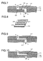
- FIG. 7 is a partial cross-sectional view of three stacked plates according to the present invention.
- FIG. 8 is an exploded view of two plates from a spin pack showing an alternate configuration of the present invention.
- FIG. 9 is the partial cross-sectional view of FIG. 7, showing an optional filtering insert.
- FIG. 10 is a partial cross-section similar to FIG. 7 but showing an alternate optional filtering insert.
- the present invention involves thin plates having polymer flow holes and channels cut through them.
- a stack of two or more of these plates can be used in forming multicomponent fibers or mixed component yarns having various cross-sections.
- These plates are inexpensive and disposable, and have a high degree of design flexibility.
- the flow holes and channels may be cut through using electro-discharge machining (EDM), drilling, cutting (including laser cutting) or stamping.
- EDM electro-discharge machining
- Preferable machining techniques are those which allow for a wide selection of plate materials so long as the materials do not creep under the spinning conditions and do not adversely react with the polymers.
- Possible materials include both ferrous and non-ferrous metals, ceramics and high temperature thermoplastics.
- the high temperature thermoplastics can even be injection molded. While methods for machining, eroding, stamping, injecting, etc., are readily available in the art, for convenience, an example of how a plate may be made is provided in Example 1.
- the thin distribution flow plate sets of the present invention include pattern plates and boundary plates. Unlike other comparable thin distribution plates, the disclosed pattern plates have transverse channels cut completely through from the upstream surface to the downstream surface. The surface of the next adjacent downstream plate serves as the bottom or boundary of the flow channel. Therefore, each thin plate contains only one feature, i.e., arrangement of channels and holes to distribute melt flow in a predetermined manner. Greater flexibility relative to other more complicated flow distribution plates is provided.
- Assembly 10 includes the following plates sealingly adjoining each other: polymer inlet block 11; metering plate 12; first pattern plate 13; boundary plate 14; second pattern plate 15 and spinneret plate 16. Fluid flow is from inlet block 11 to spinneret plate 16.
- the parts of the assembly may be bolted together and to the spinning equipment by means of bolt holes 19.
- Polymer inlet block 11 includes holes for receiving each type of polymer being extruded. In this example there are two polymers, sheath and core, so that two polymer inlet orifices 17 and 18 are shown.
- metering plate 12 Downstream of polymer inlet block 11 is metering plate 12 which contains metering holes 22 and 23 which receive polymer from core channels 20 and sheath channel 21, respectively.
- Metering holes 22 receive core polymer from distribution channels 20 (FIG. 2) and route it to distribution slot 24 cut-through first pattern plate 13.
- Metering holes 23 receive polymer from sheath distribution channel 21 (FIG. 2) and convey it to holes 25 cut through first pattern plate 13 and to holes 27 cut through boundary plate 14 which sealingly adjoins first pattern plate 13.
- boundary plate 14 confines the core polymer within cut channel 24 whereby the core polymer fills channel 24 and is forced to exit through cut hole 26 in boundary plate 14.
- Pattern plate 15 has star shaped holes cut through its thickness.
- the center of the star aligns with the center of backhole 29 of spinning orifice 30 in spinneret plate 16.
- the four corners of star holes 28 are located outside the perimeter of backhole 29.
- Sheath polymer streams from holes 27 in boundary plate 14 flow into the corners of star holes 28. Because the bottom surface of boundary plate 14 confines the streams to star hole 28, the sheath streams flow laterally into the backhole 29. Therefore, boundary plate 14 forms the lower boundary for channel 24 and the upper boundary for star hole 28.
- the core polymer stream from hole 26 of plate 14 flows into the center of star hole 28 and down into backhole 29 where it is surrounded by sheath streams.
- molten polymers may be fed to the assembly by any suitable conventional means.
- Molten core polymer enters the assembly through polymer inlet 17 shown in the elevational cross-section of FIG. 2.
- Inlet 17 splits into feed legs 31 and 32 which feed the two main distribution channels 20.
- Molten sheath polymer enters through inlet 18 shown in the elevational cross-section of FIG. 3 and flows to main distribution channel 21.
- FIG. 7 further illustrates the general principle of the present invention. Shown in FIG. 7 are three plates of a spin pack in partial cross-section. These plates illustrate the boundary/pattern plate concept. As shown, plates 111 and 112 are boundary plates and plate 113 is a pattern plate. Polymer flow is in the direction of arrows P. Polymer passes through the cut-through portion (through hole 115) because through hole 115 overlaps pattern 117 in plate 113. Pattern 117 allows transverse flow of the polymer, i.e., transverse to the polymer flow in the through hole 115, of the polymer because a horizontal flow channel 118 is formed by the faces 121 and 123 of boundary plates 111 and 112, respectively. The horizontal flow path directs the polymer to through hole 125 because hole 125 overlaps with pattern 117.
- FIG. 8 shows in exploded partial elevational perspective view of dual function plates 211 and 213.
- Upper dual function plate 211 has elongated slots 215 cut through its thickness.
- Lower dual function plate 213 also has elongated slots 216 cut through its thickness. Immediately adjacent slots 215 and 216 overlap so that they are in fluid flow communication. Yet, these slots are oriented at 90° relative to each other so that polymer passing from slot 215 into slot 216 will change its course by 90°.
- filtering means for filtering molten polymer passing therethrough may be incorporated into the apparatus.
- said filtering means are a porous material, which is inserted in the flow distribution patterns.
- porous metal inserts may be placed within the cut of a pattern plate. As shown in FIG. 9, porous metal insert 310 has the dimensions of cut (pattern) 117 in plate 113. Polymer flow (P) passing through porous metal insert 310 will be filtered.
- Porous plate 410 is inserted between pattern plate 113 and boundary plate 112. Polymer flow (P) passing through porous plate 410 will be filtered.
- a process for spinning polymers is also envisioned as part of the present invention.
- the process is for melt spinning molten thermoplastic polymers.
- An apparatus of the present invention is useful in the process of the present invention.
- one or more molten polymer streams enter a spin pack.
- the polymers are distributed as discrete streams from the inlet to the backhole of a spinneret where they may or may not meet, depending on the particular cross-section being extruded. Distribution is accomplished by routing the polymer through holes and into channels where the channels are bounded by at least the plate immediately above or below. Alternatively, the channels are bounded by both the plates above and below.
- the polymer flows transversely (or perpendicular) to the flow in the holes. Eventually, the polymer exits the channel through another hole in the plate immediately below.
- a preferred embodiment of the present invention is a spin pack for spinning synthetic fibers from two or more liquid polymer streams comprising: means for supplying at least two polymer streams to said spin pack; a spinneret having extrusion orifices; and flow distribution plate sets comprising:
- the apparatus and process of the present invention are useful for melt spinning thermoplastic polymers according to known or to be developed conditions, e.g., temperature, denier, speed, etc., for any melt spinnable polymer.
- Post extrusion treatment of the fibers may also be according to standard procedures.
- the resulting fibers are suitable for use as expected for fibers of the type.
- the x-y coordinates of 24 circular holes and 6 oblong holes are programmed into a numerically controlled EDM machine supplied by Schiess Nassovir with a 0.096 micron spark width correction (offset).
- a 0.5 mm thick stainless steel plate is sandwiched between two 2 mm thick support plates and fastened into the frame opening of the EDM machine with help of three clamps.
- a 0.5 mm diameter hole is drilled into the center of each hole and channel to be eroded and a 0.15 mm brass wire electrode is threaded through the hole. The wire is properly tensioned.
- the cutting voltage is 70 volts.
- the table with the plate assembly is guided by means of the computerized x-y guidance program to achieve the desired pattern after the power has been turned on. While cutting, the brass wire electrode is forwarded at a rate of 8 mm/sec and the plate assembly advances at a cutting rate of 3.7 mm/min.
- the brass wire electrode is flushed with demineralized water with a conductivity of 2 x 10 E4 Ohm cm with a nozzle pressure of 0.5 kg/cm 2 .
- the support plates are discarded.
- Thin distribution plates having cuts similar to the plates shown in FIGS. 4, 5 and 6 are machined from 26 gauge (0.018" ⁇ 0,46 cm) 430 stainless steel.
- the plates are inserted between a reusable spinneret and a metering plate.
- a top plate having polymer inlets is located upstream of the metering plate.
- the top plate, metering plate, thin distribution plates and spinneret are cylindrical in shape. These plates are positioned into a spinneret housing with through bolts which provide a clamping force to seal the surfaces of the plates.
- the sheath polymer is nylon 6 having an RV of approximately 2.4 (measured at a concentration of 1 g of polymer per 100 ml in 96% strength by weight sulfuric acid at a temperature of 25°C). The temperature of the molten sheath polymer is controlled at 278°C.
- the core polymer is nylon 6 having an RV of approximately 2.7 (measured at a concentration of 1 g of polymer per 100 ml of 96% strength by weight sulfuric acid at a temperature of 25°C). The temperature of the molten core polymer is controlled at 288°C.
- the spin pack and spinneret are controlled at 285°C. Each spinneret has two groups of three capillaries having a diameter of 200 microns and a length of 400 microns.
- the fibers are quenched as they exit the spinneret by a stream of cross flowing air having a velocity of approximately 30 m/min.
- the yarns make an "S" shaped path across a pair of godets before being wound onto a bobbin.
- the surface velocities of the first and second godets is 1050 and 1054 m/min respectively.
- the yarn has a velocity of 1058 m/min at the winder.
- a water-based finish dispersion is applied to the yarns prior to winding.
- Three filament 50 denier yarn is spun from the plate assembly. Each filament is a round, concentric, sheath/core bicomponent having a core which makes up 10% of the total fiber cross-sectional area
- the resulting sheath/core yarns have good physical properties as demonstrated from the following table.
- TABLE Denier Breaking Load (g) Tenacity (g/den) Elongation at 1% (%) Modulus at 10% (g/den) Modulus (g/den) Avg. 49.6 58.67 1.18 413.89 3.41 2.63 Std. Dev. 0.02 2.27 0.05 15.65 2.78 0.11
Landscapes
- Engineering & Computer Science (AREA)
- Mechanical Engineering (AREA)
- Textile Engineering (AREA)
- Spinning Methods And Devices For Manufacturing Artificial Fibers (AREA)
Claims (7)
- Empilements de filage, pour le filage de fibres synthétiques à partir d'un ou de plusieurs écoulements de polymère liquide, caractérisés para) un moyen pour fournir au moins deux écoulements de polymère audit empilement de filage, ledit moyen de fourniture étant situé en amont dudit empilement de filage,b) une filière dont le côté amont est doté de trous arrière, et le côté aval d'orifice d'extrusion, ladite filière constituant l'extrémité aval dudit empilement de filage,c) disposée entre ledit moyen de fourniture et ladite filière de manière à permettre l'écoulement du fluide entre ledit moyen de fourniture et ladite filière, au moins un jeu de plaques de répartition d'écoulement comportant:lesdits jeux de plaques de répartition d'écoulement définissant des parcours d'écoulement distincts permettant à chaque écoulement de polymère liquide de traverser chaque jeu de plaques de répartition d'écoulement sous la forme d'un écoulement distinct dirigé vers lesdits trous arrière, sans se mélanger à un autre écoulement distinct.c1) au moins une plaque structurée dont les bords définissent une forme géométrique bidimensionnelle essentiellement régulière, avec une surface amont essentiellement plane une surface aval essentiellement plane et découpée par au moins un motif de répartition d'écoulement, ledit motif de répartition d'écoulement reliant ladite surface amont et ladite surface aval; etc2) au moins une plaque frontière empilée de manière étanche sur chaque plaque structurée et dotée de bords qui définissent une forme géométrique essentiellement régulière, d'une surface amont essentiellement plane et d'une surface aval essentiellement plane, ladite plaque frontière étant traversée par des trous reliant ladite surface amont et ladite surface aval de manière à former au moins un canal de traversée en vue de permettre un écoulement de fluide à travers ladite plaque structurée, et qui pour le reste est essentiellement pleine, avec des parties pleines là où ladite plaque structurée est découpée, pour permettre un écoulement de fluide dans une direction transversale à l'écoulement dans ledit canal de traversée,
- Empilements de filage selon la revendication 1, dans lesquels une ou plusieurs desdites plaques structurées et desdites plaques frontière sont réalisées en un matériau choisi dans le groupe constitué des métaux ferreux, des métaux non ferreux, des céramiques et des thermoplastiques à haute température.
- Empilements de filage selon la revendication 1 ou la revendication 2, comportant en outre des moyens de filtration disposés entre lesdits moyens d'alimentation et lesdits jeux de plaques de répartition, lesdits moyens de filtration étant dotés d'un agent filtrant servant à filtrer le polymère fondu qui les traverse.
- Empilements de filage selon la revendication 3, dans lesquels lesdits moyens filtrant sont constitués d'un matériau poreux.
- Empilements de filage selon la revendication 3 ou la revendication 4, dans lesquels lesdits moyens filtrants sont insérés dans lesdits motifs de répartition d'écoulement.
- Empilements de filage selon les revendications 3 à 5, dans lesquels lesdits moyens filtrants sont insérés entre ladite plaque structurée et ladite plaque frontière.
- Procédé pour le filage de fibres à partir de polymère synthétique, par introduction de deux ou plusieurs écoulements de polymère liquide dans un empilement de filage selon les revendications 1 à 6.
Priority Applications (7)
| Application Number | Priority Date | Filing Date | Title |
|---|---|---|---|
| CA002107930A CA2107930C (fr) | 1992-10-29 | 1993-10-07 | Plaques de repartition du flux |
| US08/138,907 US5533883A (en) | 1992-10-29 | 1993-10-18 | Spin pack for spinning synthetic polymeric fibers |
| AT94104861T ATE161057T1 (de) | 1994-03-28 | 1994-03-28 | Strömungsverteilerplatten |
| EP94104861A EP0677600B1 (fr) | 1992-10-29 | 1994-03-28 | Plaques de distribution d'écoulement |
| DE1994607268 DE69407268T2 (de) | 1994-03-28 | 1994-03-28 | Strömungsverteilerplatten |
| JP07604894A JP3484218B2 (ja) | 1992-10-29 | 1994-04-14 | 流体流分配板体、合成樹脂紡糸方法、流体流分配板体組立て方法および合成繊維紡糸パック |
| US08/447,516 US5575063A (en) | 1992-10-29 | 1995-05-23 | Melt-spinning synthetic polymeric fibers |
Applications Claiming Priority (3)
| Application Number | Priority Date | Filing Date | Title |
|---|---|---|---|
| US96855792A | 1992-10-29 | 1992-10-29 | |
| EP94104861A EP0677600B1 (fr) | 1992-10-29 | 1994-03-28 | Plaques de distribution d'écoulement |
| JP07604894A JP3484218B2 (ja) | 1992-10-29 | 1994-04-14 | 流体流分配板体、合成樹脂紡糸方法、流体流分配板体組立て方法および合成繊維紡糸パック |
Publications (2)
| Publication Number | Publication Date |
|---|---|
| EP0677600A1 EP0677600A1 (fr) | 1995-10-18 |
| EP0677600B1 true EP0677600B1 (fr) | 1997-12-10 |
Family
ID=27235774
Family Applications (1)
| Application Number | Title | Priority Date | Filing Date |
|---|---|---|---|
| EP94104861A Expired - Lifetime EP0677600B1 (fr) | 1992-10-29 | 1994-03-28 | Plaques de distribution d'écoulement |
Country Status (4)
| Country | Link |
|---|---|
| US (2) | US5533883A (fr) |
| EP (1) | EP0677600B1 (fr) |
| JP (1) | JP3484218B2 (fr) |
| CA (1) | CA2107930C (fr) |
Families Citing this family (24)
| Publication number | Priority date | Publication date | Assignee | Title |
|---|---|---|---|---|
| US5516476A (en) * | 1994-11-08 | 1996-05-14 | Hills, Inc, | Process for making a fiber containing an additive |
| US5827582A (en) * | 1996-11-15 | 1998-10-27 | Ceramtec North America Innovative | Object with a small orifice and method of making the same |
| US5869181A (en) * | 1997-01-10 | 1999-02-09 | Basf Corporation | Multiple domain fibers and methods of making the same |
| US5879801A (en) * | 1997-01-10 | 1999-03-09 | Basf Corporation | Multiple domain fibers having inter-domain boundary compatibilizing layer and methods and apparatus for making the same |
| US5922462A (en) * | 1997-02-19 | 1999-07-13 | Basf Corporation | Multiple domain fibers having surface roughened or mechanically modified inter-domain boundary and methods of making the same |
| US6361736B1 (en) | 1998-08-20 | 2002-03-26 | Fiber Innovation Technology | Synthetic fiber forming apparatus for spinning synthetic fibers |
| US6964931B2 (en) * | 2000-03-03 | 2005-11-15 | Polymer Group, Inc. | Method of making continuous filament web with statistical filament distribution |
| TWI237710B (en) | 2001-07-03 | 2005-08-11 | Honeywell Int Inc | High-strength thin sheath fibers |
| EP1304401B1 (fr) * | 2001-10-18 | 2006-06-21 | Fiber Innovation Technology | Dispositif et procédé pour le filage de fibres synthétiques |
| US20040264899A1 (en) * | 2003-06-13 | 2004-12-30 | Peterson James F. | Flat plastic optical fiber and illumination apparatus using such fiber |
| DK1486591T3 (da) * | 2003-06-13 | 2006-03-27 | Reifenhaeuser Gmbh & Co Kg | Anordning til fremstilling af filamenter |
| US20040251567A1 (en) * | 2003-06-13 | 2004-12-16 | Pierluigi Cappellini | Method and system for producing plastic optical fiber |
| US20050087900A1 (en) * | 2003-10-23 | 2005-04-28 | Nordson Corporation | Spundbonding spin pack characterized by uniform polymer distribution and method of use |
| US20050133948A1 (en) * | 2003-12-22 | 2005-06-23 | Cook Michael C. | Apparatus and method for multicomponent fibers |
| US7168932B2 (en) | 2003-12-22 | 2007-01-30 | Kimberly-Clark Worldwide, Inc. | Apparatus for nonwoven fibrous web |
| US20070098984A1 (en) * | 2005-11-01 | 2007-05-03 | Peterson James F Ii | Fiber with release-material sheath for papermaking belts |
| WO2007134192A2 (fr) * | 2006-05-10 | 2007-11-22 | Armark Authentication Technologies, Inc. | Filament extrudé possédant un codage/indice en coupe de haute définition, système d'étiquetage microscopique formé de ce filament et procédé d'utilisation de celui-ci pour authentifier et lutter contre la contrefaçon |
| CN101939469B (zh) * | 2007-08-02 | 2012-07-04 | 北卡罗来纳州立大学 | 混合纤维和由其制备的非织造织物 |
| KR20100087321A (ko) * | 2007-10-11 | 2010-08-04 | 조지아 테크 리서치 코포레이션 | 탄소 섬유 및 필름, 및 이들의 제조 방법 |
| DE112008003614A5 (de) * | 2008-03-14 | 2011-01-27 | Oerlikon Textile Gmbh & Co. Kg | Vorrichtung zum Schmelzspinnen von Mehrkomponentenfasern |
| US8722757B2 (en) | 2011-07-22 | 2014-05-13 | Ut-Battelle, Llc | Fiber-based adsorbents having high adsorption capacities for recovering dissolved metals and methods thereof |
| CN103114345B (zh) * | 2013-02-05 | 2015-04-15 | 临邑大正特纤新材料有限公司 | Aba型导电纤维制备工艺和纺丝用分配板 |
| CN104775172B (zh) * | 2015-03-30 | 2017-09-19 | 临邑大正特纤新材料有限公司 | 海岛纤维纺丝组件 |
| JP7052724B2 (ja) * | 2017-06-28 | 2022-04-12 | 東レ株式会社 | 紡糸用パックおよび繊維の製造方法 |
Family Cites Families (25)
| Publication number | Priority date | Publication date | Assignee | Title |
|---|---|---|---|---|
| GB596010A (en) * | 1945-07-13 | 1947-12-24 | William Pool | Improvements in the production of artificial filaments and the like |
| US3050774A (en) * | 1957-09-03 | 1962-08-28 | Du Pont | Spinneret assembly |
| NL125332C (fr) * | 1962-06-25 | |||
| US3204290A (en) * | 1962-12-27 | 1965-09-07 | Monsanto Co | Laminated spinneret |
| US3501805A (en) * | 1963-01-03 | 1970-03-24 | American Cyanamid Co | Apparatus for forming multicomponent fibers |
| US3204209A (en) * | 1963-05-03 | 1965-08-31 | Toko Radio Coil Kenkyusho Kk | Variable-inductance tuner |
| US3245113A (en) * | 1963-06-10 | 1966-04-12 | American Cyanamid Co | Apparatus for forming multi-component fibers |
| US3467124A (en) * | 1966-05-04 | 1969-09-16 | Glass John P | Fluidic device |
| DE1969216U (de) * | 1966-10-24 | 1967-09-28 | Du Pont | Spinnpackung. |
| US3613170A (en) * | 1969-05-27 | 1971-10-19 | American Cyanamid Co | Spinning apparatus for sheath-core bicomponent fibers |
| US3777344A (en) * | 1969-05-28 | 1973-12-11 | Cava Ind | Method of fabricating fluidic elements by assembling together a plurality of plastic strips |
| US3704971A (en) * | 1969-06-16 | 1972-12-05 | Du Pont | Spinneret assembly |
| GB1381865A (en) * | 1971-04-20 | 1975-01-29 | Ici Ltd | Conjugate filaments apparatus |
| JPS5115124B1 (fr) * | 1971-05-04 | 1976-05-14 | ||
| US3762850A (en) * | 1971-07-26 | 1973-10-02 | Akzona Inc | Spinning head |
| US3787162A (en) * | 1972-04-13 | 1974-01-22 | Ici Ltd | Conjugate filaments apparatus |
| JPS6010122B2 (ja) * | 1975-09-11 | 1985-03-15 | アライドケミカルコーポレーシヨン | スピンポツト |
| DE2826790C2 (de) * | 1978-06-19 | 1985-02-21 | Akzo Gmbh, 5600 Wuppertal | Spinnkopf zur Herstellung von Mehrkomponentenfäden |
| US4439487A (en) * | 1982-12-17 | 1984-03-27 | E. I. Du Pont De Nemours & Company | Polyester/nylon bicomponent flament |
| US4593446A (en) * | 1984-04-18 | 1986-06-10 | Hayner Paul F | Method of manufacturing a fluid flow restrictor |
| SU1335579A1 (ru) * | 1986-04-15 | 1987-09-07 | Всесоюзный научно-исследовательский институт синтетического волокна | Фильерный комплект |
| US5162074A (en) * | 1987-10-02 | 1992-11-10 | Basf Corporation | Method of making plural component fibers |
| EP0413688B1 (fr) * | 1987-10-02 | 1994-06-22 | Basf Corporation | Procédé et appareil pour la fabrication de fibres profilées à composants multiples |
| US5227109A (en) * | 1992-01-08 | 1993-07-13 | Wellman, Inc. | Method for producing multicomponent polymer fibers |
| US5234650A (en) * | 1992-03-30 | 1993-08-10 | Basf Corporation | Method for spinning multiple colored yarn |
-
1993
- 1993-10-07 CA CA002107930A patent/CA2107930C/fr not_active Expired - Lifetime
- 1993-10-18 US US08/138,907 patent/US5533883A/en not_active Expired - Lifetime
-
1994
- 1994-03-28 EP EP94104861A patent/EP0677600B1/fr not_active Expired - Lifetime
- 1994-04-14 JP JP07604894A patent/JP3484218B2/ja not_active Expired - Fee Related
-
1995
- 1995-05-23 US US08/447,516 patent/US5575063A/en not_active Expired - Lifetime
Also Published As
| Publication number | Publication date |
|---|---|
| CA2107930C (fr) | 2000-07-11 |
| US5533883A (en) | 1996-07-09 |
| JPH07278939A (ja) | 1995-10-24 |
| EP0677600A1 (fr) | 1995-10-18 |
| CA2107930A1 (fr) | 1994-04-30 |
| JP3484218B2 (ja) | 2004-01-06 |
| US5575063A (en) | 1996-11-19 |
Similar Documents
| Publication | Publication Date | Title |
|---|---|---|
| EP0677600A1 (fr) | Plaques de distribution d'écoulement | |
| EP0646663B1 (fr) | Filière pour fusian-soufflage | |
| JP3134959B2 (ja) | 複合メルトブロー紡糸口金装置 | |
| US5137369A (en) | Static mixing device | |
| KR950001645B1 (ko) | 다성분 합성섬유의 제조방법 및 이에 사용되는 방사 팩 조립체 | |
| US5620644A (en) | Melt-spinning synthetic polymeric fibers | |
| DE69512804T2 (de) | Schnellspinnen von Mehrkomponentenfasern mit hochperforierten Spinndüsen und Kühlung mit hoher Geschwindigkeit | |
| US5556589A (en) | Process of using a spin pack for multicomponent fibers | |
| US6605248B2 (en) | Process and apparatus for making multi-layered, multi-component filaments | |
| CN101970731A (zh) | 用于熔融纺制多组分纤维的装置 | |
| DE68908745T2 (de) | Verfahren und Düse zum Schmelzblasspinnen. | |
| EP0626471A1 (fr) | Dispositif pour changer le nombre ainsi que la grosseur de filaments | |
| EP0455897B1 (fr) | Dispositif pour la fabrication de fibres trés fines | |
| US6773531B2 (en) | Process and apparatus for making multi-layered, multi-component filaments | |
| EP0409207B1 (fr) | Dispositif pour le filage de fibres âme-gaine | |
| KR100300778B1 (ko) | 둘이상의액체중합체스트림으로부터합성섬유를용융방적하기위한스핀팩및상기합성섬유를용융방적하기위한방법 | |
| EP1354081B1 (fr) | Ensemble de filiere destine a former des fibres creuses | |
| US6746226B2 (en) | Spinnerette assembly for forming multicomponent hollow fibers | |
| EP0931026A1 (fr) | Dispositif de filage de fibres de verre | |
| JPH0978334A (ja) | 多成分繊維の紡糸方法及び紡糸パック |
Legal Events
| Date | Code | Title | Description |
|---|---|---|---|
| PUAI | Public reference made under article 153(3) epc to a published international application that has entered the european phase |
Free format text: ORIGINAL CODE: 0009012 |
|
| 17P | Request for examination filed |
Effective date: 19940825 |
|
| AK | Designated contracting states |
Kind code of ref document: A1 Designated state(s): AT BE CH DE FR GB IE IT LI LU NL SE |
|
| 17Q | First examination report despatched |
Effective date: 19960621 |
|
| GRAG | Despatch of communication of intention to grant |
Free format text: ORIGINAL CODE: EPIDOS AGRA |
|
| GRAG | Despatch of communication of intention to grant |
Free format text: ORIGINAL CODE: EPIDOS AGRA |
|
| GRAH | Despatch of communication of intention to grant a patent |
Free format text: ORIGINAL CODE: EPIDOS IGRA |
|
| GRAH | Despatch of communication of intention to grant a patent |
Free format text: ORIGINAL CODE: EPIDOS IGRA |
|
| GRAA | (expected) grant |
Free format text: ORIGINAL CODE: 0009210 |
|
| AK | Designated contracting states |
Kind code of ref document: B1 Designated state(s): AT BE CH DE FR GB IE IT LI LU NL SE |
|
| REF | Corresponds to: |
Ref document number: 161057 Country of ref document: AT Date of ref document: 19971215 Kind code of ref document: T |
|
| REG | Reference to a national code |
Ref country code: CH Ref legal event code: NV Representative=s name: SCHMAUDER & WANN PATENTANWALTSBUERO, INHABER KLAUS Ref country code: CH Ref legal event code: EP |
|
| REF | Corresponds to: |
Ref document number: 69407268 Country of ref document: DE Date of ref document: 19980122 |
|
| ITF | It: translation for a ep patent filed | ||
| ET | Fr: translation filed | ||
| REG | Reference to a national code |
Ref country code: IE Ref legal event code: FG4D Free format text: 77840 |
|
| PLBE | No opposition filed within time limit |
Free format text: ORIGINAL CODE: 0009261 |
|
| STAA | Information on the status of an ep patent application or granted ep patent |
Free format text: STATUS: NO OPPOSITION FILED WITHIN TIME LIMIT |
|
| 26N | No opposition filed | ||
| REG | Reference to a national code |
Ref country code: GB Ref legal event code: IF02 |
|
| REG | Reference to a national code |
Ref country code: CH Ref legal event code: PUE Owner name: HONEYWELL INTERNATIONAL INC. Free format text: BASF CORPORATION#8 CAMPUS DRIVE#PARSIPPANY, NEW JERSEY 07054 (US) -TRANSFER TO- HONEYWELL INTERNATIONAL INC.#101 COLUMBIA ROAD#MORRISTOWN, NJ 07960 (US) Ref country code: CH Ref legal event code: NV Representative=s name: SCHMAUDER & PARTNER AG PATENTANWALTSBUERO |
|
| REG | Reference to a national code |
Ref country code: GB Ref legal event code: 732E |
|
| BECA | Be: change of holder's address |
Owner name: *HONEYWELL INTERNATIONAL INC.15801 WOODS EDGE ROAD Effective date: 20060608 |
|
| REG | Reference to a national code |
Ref country code: CH Ref legal event code: PCAR Free format text: SCHMAUDER & PARTNER AG PATENT- UND MARKENANWAELTE VSP;ZWAENGIWEG 7;8038 ZUERICH (CH) |
|
| PGFP | Annual fee paid to national office [announced via postgrant information from national office to epo] |
Ref country code: LU Payment date: 20100629 Year of fee payment: 17 Ref country code: IE Payment date: 20100625 Year of fee payment: 17 |
|
| PGFP | Annual fee paid to national office [announced via postgrant information from national office to epo] |
Ref country code: AT Payment date: 20100625 Year of fee payment: 17 |
|
| PGFP | Annual fee paid to national office [announced via postgrant information from national office to epo] |
Ref country code: CH Payment date: 20100629 Year of fee payment: 17 |
|
| PGFP | Annual fee paid to national office [announced via postgrant information from national office to epo] |
Ref country code: SE Payment date: 20100622 Year of fee payment: 17 |
|
| REG | Reference to a national code |
Ref country code: NL Ref legal event code: SD Effective date: 20101122 |
|
| REG | Reference to a national code |
Ref country code: CH Ref legal event code: PL |
|
| REG | Reference to a national code |
Ref country code: SE Ref legal event code: EUG |
|
| PG25 | Lapsed in a contracting state [announced via postgrant information from national office to epo] |
Ref country code: AT Free format text: LAPSE BECAUSE OF NON-PAYMENT OF DUE FEES Effective date: 20110328 |
|
| REG | Reference to a national code |
Ref country code: IE Ref legal event code: MM4A |
|
| PG25 | Lapsed in a contracting state [announced via postgrant information from national office to epo] |
Ref country code: LI Free format text: LAPSE BECAUSE OF NON-PAYMENT OF DUE FEES Effective date: 20110331 Ref country code: CH Free format text: LAPSE BECAUSE OF NON-PAYMENT OF DUE FEES Effective date: 20110331 Ref country code: IE Free format text: LAPSE BECAUSE OF NON-PAYMENT OF DUE FEES Effective date: 20110328 |
|
| PGFP | Annual fee paid to national office [announced via postgrant information from national office to epo] |
Ref country code: IT Payment date: 20120320 Year of fee payment: 19 |
|
| PG25 | Lapsed in a contracting state [announced via postgrant information from national office to epo] |
Ref country code: SE Free format text: LAPSE BECAUSE OF NON-PAYMENT OF DUE FEES Effective date: 20110329 |
|
| PGFP | Annual fee paid to national office [announced via postgrant information from national office to epo] |
Ref country code: GB Payment date: 20130225 Year of fee payment: 20 Ref country code: FR Payment date: 20130315 Year of fee payment: 20 |
|
| PG25 | Lapsed in a contracting state [announced via postgrant information from national office to epo] |
Ref country code: LU Free format text: LAPSE BECAUSE OF NON-PAYMENT OF DUE FEES Effective date: 20110328 |
|
| PGFP | Annual fee paid to national office [announced via postgrant information from national office to epo] |
Ref country code: BE Payment date: 20130410 Year of fee payment: 20 Ref country code: DE Payment date: 20130328 Year of fee payment: 20 |
|
| PGFP | Annual fee paid to national office [announced via postgrant information from national office to epo] |
Ref country code: NL Payment date: 20130312 Year of fee payment: 20 |
|
| REG | Reference to a national code |
Ref country code: DE Ref legal event code: R071 Ref document number: 69407268 Country of ref document: DE |
|
| BE20 | Be: patent expired |
Owner name: *HONEYWELL INTERNATIONAL INC. Effective date: 20140328 |
|
| REG | Reference to a national code |
Ref country code: NL Ref legal event code: V4 Effective date: 20140328 |
|
| REG | Reference to a national code |
Ref country code: GB Ref legal event code: PE20 Expiry date: 20140327 |
|
| PG25 | Lapsed in a contracting state [announced via postgrant information from national office to epo] |
Ref country code: GB Free format text: LAPSE BECAUSE OF EXPIRATION OF PROTECTION Effective date: 20140327 Ref country code: DE Free format text: LAPSE BECAUSE OF EXPIRATION OF PROTECTION Effective date: 20140329 |