EP0677643B1 - Machine de perforation des tunnels - Google Patents
Machine de perforation des tunnels Download PDFInfo
- Publication number
- EP0677643B1 EP0677643B1 EP95890085A EP95890085A EP0677643B1 EP 0677643 B1 EP0677643 B1 EP 0677643B1 EP 95890085 A EP95890085 A EP 95890085A EP 95890085 A EP95890085 A EP 95890085A EP 0677643 B1 EP0677643 B1 EP 0677643B1
- Authority
- EP
- European Patent Office
- Prior art keywords
- tunnel
- boring
- tools
- machine
- axis
- Prior art date
- Legal status (The legal status is an assumption and is not a legal conclusion. Google has not performed a legal analysis and makes no representation as to the accuracy of the status listed.)
- Expired - Lifetime
Links
- 239000011435 rock Substances 0.000 claims description 15
- 230000007246 mechanism Effects 0.000 claims description 4
- 238000005553 drilling Methods 0.000 description 25
- 230000007480 spreading Effects 0.000 description 3
- 239000000463 material Substances 0.000 description 2
- 238000005065 mining Methods 0.000 description 2
- 238000009304 pastoral farming Methods 0.000 description 2
- 230000008439 repair process Effects 0.000 description 2
- 238000007790 scraping Methods 0.000 description 2
- 230000005641 tunneling Effects 0.000 description 2
- 229910000831 Steel Inorganic materials 0.000 description 1
- 238000004873 anchoring Methods 0.000 description 1
- 238000009412 basement excavation Methods 0.000 description 1
- 230000008901 benefit Effects 0.000 description 1
- 230000008859 change Effects 0.000 description 1
- 238000010276 construction Methods 0.000 description 1
- 230000002542 deteriorative effect Effects 0.000 description 1
- 230000008030 elimination Effects 0.000 description 1
- 238000003379 elimination reaction Methods 0.000 description 1
- 230000002996 emotional effect Effects 0.000 description 1
- 230000002349 favourable effect Effects 0.000 description 1
- 238000003754 machining Methods 0.000 description 1
- 238000012423 maintenance Methods 0.000 description 1
- 238000000034 method Methods 0.000 description 1
- 230000009467 reduction Effects 0.000 description 1
- 238000006049 ring expansion reaction Methods 0.000 description 1
- 239000010959 steel Substances 0.000 description 1
- 239000004575 stone Substances 0.000 description 1
Images


Classifications
-
- E—FIXED CONSTRUCTIONS
- E21—EARTH OR ROCK DRILLING; MINING
- E21D—SHAFTS; TUNNELS; GALLERIES; LARGE UNDERGROUND CHAMBERS
- E21D9/00—Tunnels or galleries, with or without linings; Methods or apparatus for making thereof; Layout of tunnels or galleries
- E21D9/10—Making by using boring or cutting machines
- E21D9/11—Making by using boring or cutting machines with a rotary drilling-head cutting simultaneously the whole cross-section, i.e. full-face machines
- E21D9/112—Making by using boring or cutting machines with a rotary drilling-head cutting simultaneously the whole cross-section, i.e. full-face machines by means of one single rotary head or of concentric rotary heads
-
- E—FIXED CONSTRUCTIONS
- E21—EARTH OR ROCK DRILLING; MINING
- E21D—SHAFTS; TUNNELS; GALLERIES; LARGE UNDERGROUND CHAMBERS
- E21D9/00—Tunnels or galleries, with or without linings; Methods or apparatus for making thereof; Layout of tunnels or galleries
- E21D9/10—Making by using boring or cutting machines
- E21D9/1006—Making by using boring or cutting machines with rotary cutting tools
- E21D9/104—Cutting tool fixtures
-
- E—FIXED CONSTRUCTIONS
- E21—EARTH OR ROCK DRILLING; MINING
- E21D—SHAFTS; TUNNELS; GALLERIES; LARGE UNDERGROUND CHAMBERS
- E21D9/00—Tunnels or galleries, with or without linings; Methods or apparatus for making thereof; Layout of tunnels or galleries
- E21D9/10—Making by using boring or cutting machines
- E21D9/1093—Devices for supporting, advancing or orientating the machine or the tool-carrier
Definitions
- the invention relates to a tunnel boring machine or Pipe jacking machine for hard rock drilling with a die Rotating full cut drill head carrying drilling tools.
- EP 520 909 A1 includes a tunnel boring machine a drill head in the form of a disc and a hollow shaft
- the extension has become known, which is connected to two drives stands, whereby the drill head is rotated.
- the drill head is in a ring joint over the shaft part, consisting of rings opposite an outer ring, which the Shield forms, stored.
- the multi-ring joint consists of one or more rings that are not concentric with each other stand, whereby when the or the Inner rings opposite the inner ring of the shield and the drill head shaft the axis of rotation of the drill head in any eccentric position to the longitudinal axis of the tunnel can. This measure is particularly advantageous if wear of the drill bits is to be compensated for or a Overlap is needed around the tunnel boring machine and the Insert the drill head into the curvature.
- the invention now aims to set up a device mentioned type to the extent that without mechanical additional facilities the entire face can be dismantled and withdrawn if necessary can be done from the tunnel tube without digging.
- the drill according to the invention or Tunneling machine of the type mentioned at the outset essentially in that the drill head and the enveloping circle of the tools unite Have diameter that is smaller than the diameter the bore and that the geometric axis of the enveloping circle Tools of the full cut drilling head relative to the axis of rotation eccentrically arranged or displaceable.
- the geometrical The axis of the full cut drill head is defined here through the enveloping circle of the tools on the full cut drilling head, and a rotation of such a drill head about an axis of rotation, which is different from the geometric axis, leads to the fact that a larger cross section can be reduced, than this corresponds to the cross section of the full cut drill head alone would.
- a configuration allows by simply relocating the full cut drill head To take position in which one Pull out the drill head and the entire tunnel boring machine also with existing extensions or pipework or Convergence is easily possible.
- the tunnel boring machine according to the invention or Pipe jacking machine developed so that the drill head a Has carrier disc on which hard rock tools such e.g. Disks are arranged, their radial distance from each other taking into account the eccentricity of the enveloping circle the disks to the longitudinal axis of the tunnel or to the axis of rotation are selected in this way is that the cutting line distances to the longitudinal axis of the tunnel larger radius are smaller than on a smaller one Radius.
- Discs or roller chisels are ideal for this as hard rock tools, with a corresponding Arrangement on the drill head with smaller ones on a larger radius Cutting line spacing a safe machining with simultaneous Reduction of the radial force components and the results in off-center loading of the drill head.
- the order the drilling tools lead to an eccentric envelope which is smaller than the raw diameter of the tunnel tube, when using a carrier plate for drilling tools this can be arranged as usual centrally to the drill head, so that Jamming of larger, detached rocks can be avoided.
- the arrangement of the individual disks in in a way that an enveloping circle of the entire drilling tool is eccentric to the pipe axis allows the dismantling of the desired clearance over the actual diameter of the Drilling tool or drill head.
- the training is advantageous to reduce wear hit that the tools are relative to the axis of the drill head arranged asymmetrically, especially along a spiral are, the disks in a particularly advantageous manner larger diameter flatter to the working face than on a smaller diameter. Both of these measures minimize wear and thus reduce the required Maintenance effort and are particularly related with the eccentricity provided according to the invention Cutting movement particularly advantageous.
- the training can be taken with advantage so that the Tunnel boring machine via sliding or movable supports is supported in the tunnel tube.
- a movable one Support can take place via a self-propulsion and for example in the form of crawler tracks.
- Such movable supports are separate from the to provide actual spreading in the tunnel tube with which is basically a step under the respective solution one of the two spreading and advancing or pulling the other spread is possible.
- the tunnel boring machine according to the invention or Pipe jacking machine developed so that the drill head by rotating the carrier disk relative to the axis of rotation the drive can be pivoted into a position in which the outer contour of the carrier disc and the drilling tools inside the projection of the clear diameter of the removed or piped tunnel on the face. in principle describe the individual disks according to their orientation a circular movement relative to the desired tunnel axis over the face.
- the drill head in one bring certain, predetermined rotational position and then the pivoting of the axis by means of a support relative to the longitudinal axis of the tunnel to withdraw to ensure.
- the Training taken so that the axis of rotation of the drive of the drilling tools through the front or rear support the tunnel boring machine in the tunnel tube relative to the longitudinal axis of the tunnel is shiftable, the tunnel boring machine in a simple manner Movable on caterpillars or rails or wheels is trained and equipped with a travel drive can be.
- a particularly favorable introduction of force with at the same time low Wear can be ensured that the Caliber tools on the carrier plate within a center angle of less than or equal to 90 ° are arranged.
- the front and the rear vertical Outriggers are usually mandatory components a double braced hard rock machine, the Stepping occurs by actuating the double tension.
- the elimination of an adjustment mechanism of the drilling tool is reduced the susceptibility to failure in harsh operating conditions in the hard rock driving.
- Envelope circle can the drilling tool through the above construction measures by different arrangement of the disks can be optimized without this deteriorating the Possibilities, the tunnel boring machine or pipe jacking machine going back would bring with it.
- the carrier plate or the drilling tool also deviates from the circular shape Have outline shape, so that by simply pivoting one Position can be taken in which the withdrawal is made possible.
- FIG. 1 shows a side view of a tunnel boring machine in the extended position
- Figure 2 is an enlarged Detailed view of the full cut head in working position
- 3 is a front view of a full cut drilling head in the working position
- 4 shows a drill head according to FIG. 3 in a raised position Position for retraction
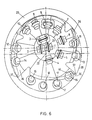
- Fig.5 another embodiment a drill head with a different arrangement of the caliber tools 6 in the working position and a transport position for the embodiment according to FIG. 5, the one shown in FIG Section line II / II essentially with the illustration according to Fig. 2.
- Fig.1 there are disks 1 to 18, of which the simplicity only discs 8 and 18 are shown, with one Drill head 19 can be seen connected.
- the drill head 19 is from a geared motor 20 rotatable about an axis of rotation 21 driven, the axis of rotation 21 for propulsion in a position is pivoted which is the longitudinal axis 22 of the tunnel equivalent.
- the lifting via a hydraulic cylinder-piston unit 23 of a movable support shoe 24 can retract while maintaining a free space 25 of the tool from the working position.
- the side supports 26 and 27 are retracted, which together with hydraulic cylinder piston units 28 form a walking mechanism.
- a rear support 29 is provided, which also sliding or with its own drive and a crawler track can be designed to be movable.
- a conveyor 30 which to subsequent conveying means 32 in the tunnel tube 31 yields.
- FIG. 2 In the illustration according to FIG. 2 is again a caliber tool 18 and a central disc 1 on the drill head 19 can be seen.
- the axis of rotation 21 coincides with the longitudinal axis 22 of the tunnel together and the hard rock drilling head is in his Working position.
- the cut material over baffles 33 is transferred to the conveyor 30 and removed can be.
- the drill head is located with disks 1 to 18 in the working position, and the axis of rotation 21 coincides with the longitudinal axis 22 of the tunnel.
- the axis of rotation 21 coincides with the longitudinal axis 22 of the tunnel.
- the cutting line distances are here, as from the 3 to 6 can be seen, chosen so that in the outer area due to a much flatter position of the drilling tools a significantly smaller cutting line distance was maintained will than in the central area of the bore.
- the cutting rollers are asymmetrical arranged to optimize for radial forces to surrender.
- the drill head instructs of the carrier plate, the grazing tools 36, the grazing edges 37 are arranged within the enveloping circle 35.
- These digging tools can optionally be rigidly connected to the carrier plate be, or for the procedure from inside the tunnel tube of the enveloping circle can be designed to be foldable.
Landscapes
- Engineering & Computer Science (AREA)
- Mining & Mineral Resources (AREA)
- Environmental & Geological Engineering (AREA)
- Life Sciences & Earth Sciences (AREA)
- General Life Sciences & Earth Sciences (AREA)
- Geochemistry & Mineralogy (AREA)
- Geology (AREA)
- Earth Drilling (AREA)
Claims (10)
- Machine de perforation des tunnels ou abatteuse-chargeuse pour creusement, pour forage en roche dure avec un bouclier de creusement en section complète (19) porteur des outils de forage (1 à 18) et monté de manière pivotante, caractérisée en ce que le bouclier (19) et le cercle d'enveloppe (35) des outils de forage (1 à 18) présentent un diamètre plus petit que le diamètre du forage et en ce que l'axe géométrique du cercle d'enveloppe (35) des outils (1 à 18) du bouclier de creusement en section complète (19) est disposé excentriquement ou peut être décalé par rapport à l'axe de rotation (21).
- Machine de perforation des tunnels ou abatteuse-chargeuse pour creusement selon la revendication 1, caractérisée en ce que le bouclier (19) présente un disque porteur (34) sur lequel sont disposés des outils de forage de roche dure (1 à 18), comme par exemple des molettes, dont la distance radiale les uns des autres, compte tenu de l'excentricité du cercle d'enveloppe des molettes (1 à 18) par rapport à l'axe longitudinal du tunnel (22), ou à l'axe de rotation (21), est choisie de telle sorte que, par rapport à l'axe longitudinal du tunnel (22), les distances des lignes de coupe soient plus grandes sur le grand rayon que sur le petit rayon.
- Machine de perforation des tunnels ou abatteuse-chargeuse pour creusement selon la revendication 1 ou 2, caractérisée en ce que les outils (1 à 18) sont disposés asymétriquement par rapport à l'axe du bouclier, en particulier le long d'une spirale.
- Machine de perforation des tunnels ou abatteuse-chargeuse pour creusement selon la revendication 1, 2 ou 3, caractérisée en ce que les molettes (11 à 18) sur le grand diamètre sont inclinées plus à plat sur la face locale que sur le petit diamètre.
- Machine de perforation des tunnels ou abatteuse-chargeuse pour creusement selon l'une des revendications 1 à 4, caractérisée en ce que la machine de perforation des tunnels est supportée au moyen d'appuis glissants ou roulants (24, 29) dans la galerie tubulaire du tunnel.
- Machine de perforation des tunnels ou abatteuse-chargeuse pour creusement selon l'une des revendications 1 à 5, caractérisée en ce que, par rotation du disque porteur (34) par rapport à l'axe de rotation (21) de l'entraínement, le bouclier (19) peut être pivoté dans une position dans laquelle le contour extérieur de la plaque porteuse (34) et des outils de forage (1 à 18) se trouve sur la face locale, à l'intérieur de la saillie du diamètre ouvert de la galerie tubulaire garnie ou cuvclée du tunnel.
- Machine de perforation des tunnels ou abatteuse-chargeuse pour creusement selon l'une des revendications 1 à 6, caractérisée en ce que l'axe de rotation (21) de l'entrainement des outils de forage (1 à 18) est décalable dans la galerie tubulaire du tunnel par rapport à l'axe longitudinal du tunnel au moyen de l'appui avant ou arrière (24, 29) de la machine de perforation des tunnels.
- Machine de perforation des tunnels ou abatteuse-chargeuse pour creusement selon l'une des revendications 1 à 7, caractérisée en ce que la machine de perforation des tunnels est conçue de façon à pouvoir se déplacer sur des chenilles (24, 29), ou sur des roues, ou sur des rails, et est munie d'un entraínement automoteur.
- Machine de perforation des tunnels ou abatteuse-chargeuse pour crcusement selon l'une des revendications 1 à 8, caractérisée en ce que les outils de calibrage (15 à 18) sont disposés sur le disque porteur (34), à l'intérieur d'un angle central inférieur ou égal à 90°.
- Machine de perforation des tunnels ou abatteuse-chargeuse pour creusement selon l'une des revendications 1 à 8, caractérisée en ce que le bouclier de forage (19) présente sur la plaque porteuse (34) des outils d'exploration dont les bords d'exploration sont disposés à l'intérieur du cercle d'enveloppe des outils de forage (1 à 18), de manière rigide ou de façon à pouvoir être rétractés à l'intérieur du cercle d'enveloppe.
Applications Claiming Priority (2)
| Application Number | Priority Date | Filing Date | Title |
|---|---|---|---|
| DE4413235A DE4413235C2 (de) | 1994-04-15 | 1994-04-15 | Tunnelbohrmaschine bzw. Rohrvortriebsmaschine |
| DE4413235 | 1994-04-15 |
Publications (2)
| Publication Number | Publication Date |
|---|---|
| EP0677643A1 EP0677643A1 (fr) | 1995-10-18 |
| EP0677643B1 true EP0677643B1 (fr) | 2002-07-03 |
Family
ID=6515625
Family Applications (1)
| Application Number | Title | Priority Date | Filing Date |
|---|---|---|---|
| EP95890085A Expired - Lifetime EP0677643B1 (fr) | 1994-04-15 | 1995-04-12 | Machine de perforation des tunnels |
Country Status (4)
| Country | Link |
|---|---|
| US (1) | US5575537A (fr) |
| EP (1) | EP0677643B1 (fr) |
| DE (2) | DE4413235C2 (fr) |
| ZA (1) | ZA952982B (fr) |
Families Citing this family (14)
| Publication number | Priority date | Publication date | Assignee | Title |
|---|---|---|---|---|
| FR2754561B1 (fr) * | 1996-10-14 | 1999-01-08 | Neyrpic Framatome Mecanique | Tete de coupe d'un tunnelier |
| DE19715095C1 (de) * | 1997-04-11 | 1998-10-15 | Gerd Dr Ing Soltau | Vorrichtung zur Lageanzeige eines schwenkbaren vorderen Teils eines lasergeführten zweiteiligen Tunnelbohrkopfes |
| DE19722000A1 (de) | 1997-05-27 | 1998-12-03 | Wirth Co Kg Masch Bohr | Tunnelbohrmaschine |
| AU779827B2 (en) * | 1999-01-20 | 2005-02-10 | Odyssey Technology Pty Ltd | Rock boring device |
| AUPP822499A0 (en) | 1999-01-20 | 1999-02-11 | Terratec Asia Pacific Pty Ltd | Oscillating & nutating disc cutter |
| AUPS186902A0 (en) * | 2002-04-22 | 2002-05-30 | Odyssey Technology Pty Ltd | Rock cutting machine |
| AUPS186802A0 (en) * | 2002-04-22 | 2002-05-30 | Odyssey Technology Pty Ltd | Oscillating disc cutter with speed controlling bearings |
| AT504281B1 (de) * | 2006-09-20 | 2010-08-15 | Voest Alpine Bergtechnik | Vollschnittstreckenvortriebsmaschine |
| CN102287203B (zh) * | 2011-08-01 | 2013-04-10 | 成都市新筑路桥机械股份有限公司 | 一种风钻工作装置 |
| EP2636799B1 (fr) * | 2012-03-05 | 2014-05-14 | Bauer Spezialtiefbau GmbH | Foreuse pour un rideau souterrain et procédé pour faire un tel rideau |
| CN102748034B (zh) * | 2012-07-19 | 2014-08-20 | 李文军 | 顶进型管道掘进机 |
| US11786622B2 (en) | 2020-05-08 | 2023-10-17 | Ultra-Violet Solutions, Llc | Far UV-C light apparatus |
| CN113374490A (zh) * | 2021-07-06 | 2021-09-10 | 中国水利水电第五工程局有限公司 | 泥水平衡式顶管系统及施工方法、纠偏控制系统 |
| CN115306416A (zh) * | 2022-08-12 | 2022-11-08 | 中国铁建重工集团股份有限公司 | 一种矿用全断面岩石隧道掘进机及其始发掘进方法 |
Family Cites Families (17)
| Publication number | Priority date | Publication date | Assignee | Title |
|---|---|---|---|---|
| US3041055A (en) * | 1959-07-13 | 1962-06-26 | Goodman Mfg Co | Rotatable cutter head |
| US3232670A (en) * | 1964-08-07 | 1966-02-01 | Robbins & Assoc James S | Tunnel-boring rotary head with adjustably mounted gauge cutters |
| AT269033B (de) * | 1966-03-11 | 1969-03-10 | Habegger Ag Maschf | Lenkvorrichtung für Stollenbohr- und -vortriebsmaschinen |
| DE1534656B1 (de) * | 1966-12-30 | 1970-04-02 | Masch Und Bohrgeraete Fabrik | Einrichtung zum Vortreiben von Tunneln,Stollen od.dgl. |
| FR1553002A (fr) * | 1967-11-17 | 1969-01-10 | ||
| US3603100A (en) * | 1969-05-05 | 1971-09-07 | Cervotec Developments Ltd | Tunnelling means and method |
| US3598445A (en) * | 1969-05-08 | 1971-08-10 | Douglas F Winberg | Tunnel-boring machine |
| US4043600A (en) * | 1975-09-22 | 1977-08-23 | Dresser Industries, Inc. | Adjustable bucket for an earth boring machine |
| IT1141170B (it) * | 1980-02-06 | 1986-10-01 | Cofimco Sas | Ventilatore assiale a pale non svergolate ed a trazione incrementata |
| US4371211A (en) * | 1980-12-11 | 1983-02-01 | Jarva, Inc. | Tunnel boring machine and method of operating same |
| US4527837A (en) * | 1983-01-27 | 1985-07-09 | Harrison Western Corporation | Tunnel boring machine |
| JPS59192193A (ja) * | 1983-04-14 | 1984-10-31 | 株式会社イセキ開発工機 | シールド掘進装置 |
| ZA842236B (en) * | 1983-05-10 | 1984-11-28 | Atlas Copco Ab | Machine for boring non-circular tunnels |
| CH672659A5 (fr) * | 1984-04-19 | 1989-12-15 | Bechem Hannelore | |
| DE3423842C2 (de) * | 1984-06-28 | 1986-05-28 | MTS Minitunnelsysteme GmbH, 3500 Kassel | Vorrichtung zum Herstellen von unterirdischen, nicht begehbare Querschnitte aufweisenden Hohlräumen |
| JPH0684718B2 (ja) * | 1991-01-17 | 1994-10-26 | 機動建設工業株式会社 | トンネル掘削装置 |
| FR2678296B1 (fr) * | 1991-06-28 | 1993-10-29 | Gtm Batiment Travaux Publics | Tunnelier comprenant une tete de coupe dont la position est reglable. |
-
1994
- 1994-04-15 DE DE4413235A patent/DE4413235C2/de not_active Expired - Fee Related
-
1995
- 1995-04-05 US US08/417,053 patent/US5575537A/en not_active Expired - Fee Related
- 1995-04-11 ZA ZA952982A patent/ZA952982B/xx unknown
- 1995-04-12 EP EP95890085A patent/EP0677643B1/fr not_active Expired - Lifetime
- 1995-04-12 DE DE59510254T patent/DE59510254D1/de not_active Expired - Fee Related
Also Published As
| Publication number | Publication date |
|---|---|
| DE59510254D1 (de) | 2002-08-08 |
| ZA952982B (en) | 1995-12-21 |
| DE4413235C2 (de) | 1999-04-29 |
| DE4413235A1 (de) | 1995-10-19 |
| EP0677643A1 (fr) | 1995-10-18 |
| US5575537A (en) | 1996-11-19 |
Similar Documents
| Publication | Publication Date | Title |
|---|---|---|
| EP0677643B1 (fr) | Machine de perforation des tunnels | |
| DE102012107485A1 (de) | Mobile Bergbaumaschine sowie Verfahren zum Auffahren von Tunneln, Strecken oder Schächten, insbesondere in Hartgestein | |
| DE2621674C3 (de) | Verfahren und Vorrichtung zum Vortrieb und Ausbau einer untertägigen Strecke sowie Streckenausbau zur Ausübung des Verfahrens | |
| EP0985082A1 (fr) | Machine a percer des tunnels | |
| DE68925283T2 (de) | Tunnelbohrmaschine mit vier schleppschritt-stützschuhen | |
| DE3920011C3 (de) | Stetig arbeitendes Gewinnungsgerät für Tagebaue mit einem walzenförmigen Gewinnungsorgan | |
| DE2437669B2 (de) | Vortriebsvorrichtung fuer das auffahren von tunneln, stollen und strecken | |
| DE2656703C2 (de) | Abbaumaschine | |
| DE2424755A1 (de) | Schutzdach fuer eine tunnelbaumaschine und mit einem solchen ausgestattete maschine | |
| DE102012107484A1 (de) | Mobile Bergbaumaschine zum Auffahren vonTunnels, Strecken oder Schächten, insbesondere in Hartgestein | |
| DE2948942A1 (de) | Schraemeinheitanordnung fuer eine vortriebsmaschine fuer strecken im bergbau und fuer tunnels und vortriebsmaschine | |
| DE2462542C3 (de) | Teilschnitt-Vortriebsmaschine für den Vortrieb von Tunneln, Stollen oder sonstigen Strecken | |
| EP0203907A1 (fr) | Jumbo pour le forage de trous d'excavation et de trous de boulonnage | |
| DE4202013A1 (de) | Vortriebsmaschine fuer den strecken- oder tunnelvortrieb u. dgl. | |
| DE2514150C3 (de) | Schildvortriebsmaschine zum Auffahren von Tunneln und Strecken | |
| DE3224514C2 (de) | Streckenvortriebsmaschine | |
| EP1760255B1 (fr) | Appareil d'abattage | |
| DE102011114589A1 (de) | Mobile Bergbaumaschine sowie Verfahren zum Auffahren von Tunnels, Strecken oder Schächten, insbesondere in Hartgestein | |
| DE1759080C2 (de) | Vorrichtung zum Versetzen von Tübbings oder Ringsegmenten für Tunnelauskleidungen | |
| DE977150C (de) | Bohrwagen fuer den Streckenvortrieb im Bergbau | |
| DE1840920U (de) | Vortriebsmaschine mit fahrwerk und konischer schraemwalze. | |
| CH615978A5 (en) | Driving shield | |
| CH645696A5 (de) | Gleitbahneinrichtung und vortriebsmaschine, die mit der gleitbahneinrichtung ausgeruestet ist. | |
| AT413127B (de) | Vortriebs- oder gewinnungsmaschine für den abbau von gestein | |
| DE2743225A1 (de) | Schreitender ausbautunnel |
Legal Events
| Date | Code | Title | Description |
|---|---|---|---|
| PUAI | Public reference made under article 153(3) epc to a published international application that has entered the european phase |
Free format text: ORIGINAL CODE: 0009012 |
|
| AK | Designated contracting states |
Kind code of ref document: A1 Designated state(s): CH DE IT LI SE |
|
| 17P | Request for examination filed |
Effective date: 19960328 |
|
| RAP1 | Party data changed (applicant data changed or rights of an application transferred) |
Owner name: TAMROCK VOEST-ALPINE BERGTECHNIK GESELLSCHAFT M.B. |
|
| RAP1 | Party data changed (applicant data changed or rights of an application transferred) |
Owner name: VOEST-ALPINE BERGTECHNIK GESELLSCHAFT M.B.H |
|
| 17Q | First examination report despatched |
Effective date: 20000302 |
|
| GRAG | Despatch of communication of intention to grant |
Free format text: ORIGINAL CODE: EPIDOS AGRA |
|
| GRAG | Despatch of communication of intention to grant |
Free format text: ORIGINAL CODE: EPIDOS AGRA |
|
| GRAH | Despatch of communication of intention to grant a patent |
Free format text: ORIGINAL CODE: EPIDOS IGRA |
|
| GRAH | Despatch of communication of intention to grant a patent |
Free format text: ORIGINAL CODE: EPIDOS IGRA |
|
| GRAA | (expected) grant |
Free format text: ORIGINAL CODE: 0009210 |
|
| AK | Designated contracting states |
Kind code of ref document: B1 Designated state(s): CH DE IT LI SE |
|
| PG25 | Lapsed in a contracting state [announced via postgrant information from national office to epo] |
Ref country code: IT Free format text: LAPSE BECAUSE OF FAILURE TO SUBMIT A TRANSLATION OF THE DESCRIPTION OR TO PAY THE FEE WITHIN THE PRE;WARNING: LAPSES OF ITALIAN PATENTS WITH EFFECTIVE DATE BEFORE 2007 MAY HAVE OCCURRED AT ANY TIME BEFORE 2007. THE CORRECT EFFECTIVE DATE MAY BE DIFFERENT FROM THE ONE RECORDED.SCRIBED TIME-LIMIT Effective date: 20020703 |
|
| REG | Reference to a national code |
Ref country code: CH Ref legal event code: EP |
|
| REF | Corresponds to: |
Ref document number: 59510254 Country of ref document: DE Date of ref document: 20020808 |
|
| PG25 | Lapsed in a contracting state [announced via postgrant information from national office to epo] |
Ref country code: SE Free format text: LAPSE BECAUSE OF FAILURE TO SUBMIT A TRANSLATION OF THE DESCRIPTION OR TO PAY THE FEE WITHIN THE PRESCRIBED TIME-LIMIT Effective date: 20021003 |
|
| PG25 | Lapsed in a contracting state [announced via postgrant information from national office to epo] |
Ref country code: LI Free format text: LAPSE BECAUSE OF NON-PAYMENT OF DUE FEES Effective date: 20030430 Ref country code: CH Free format text: LAPSE BECAUSE OF NON-PAYMENT OF DUE FEES Effective date: 20030430 |
|
| PLBE | No opposition filed within time limit |
Free format text: ORIGINAL CODE: 0009261 |
|
| STAA | Information on the status of an ep patent application or granted ep patent |
Free format text: STATUS: NO OPPOSITION FILED WITHIN TIME LIMIT |
|
| 26N | No opposition filed |
Effective date: 20030404 |
|
| REG | Reference to a national code |
Ref country code: CH Ref legal event code: PL |
|
| PGFP | Annual fee paid to national office [announced via postgrant information from national office to epo] |
Ref country code: DE Payment date: 20060419 Year of fee payment: 12 |
|
| PG25 | Lapsed in a contracting state [announced via postgrant information from national office to epo] |
Ref country code: DE Free format text: LAPSE BECAUSE OF NON-PAYMENT OF DUE FEES Effective date: 20071101 |