EP0677946B1 - Datenübertragungssteuerungsverfahren und Informationsverarbeitungssystem, das dieses benutzt - Google Patents
Datenübertragungssteuerungsverfahren und Informationsverarbeitungssystem, das dieses benutzt Download PDFInfo
- Publication number
- EP0677946B1 EP0677946B1 EP95302506A EP95302506A EP0677946B1 EP 0677946 B1 EP0677946 B1 EP 0677946B1 EP 95302506 A EP95302506 A EP 95302506A EP 95302506 A EP95302506 A EP 95302506A EP 0677946 B1 EP0677946 B1 EP 0677946B1
- Authority
- EP
- European Patent Office
- Prior art keywords
- image data
- network
- data
- compression
- image
- Prior art date
- Legal status (The legal status is an assumption and is not a legal conclusion. Google has not performed a legal analysis and makes no representation as to the accuracy of the status listed.)
- Expired - Lifetime
Links
- 238000000034 method Methods 0.000 title claims description 47
- 238000012546 transfer Methods 0.000 title claims description 46
- 230000010365 information processing Effects 0.000 title claims description 11
- 230000005540 biological transmission Effects 0.000 claims description 76
- 230000006835 compression Effects 0.000 claims description 62
- 238000007906 compression Methods 0.000 claims description 62
- 238000012545 processing Methods 0.000 claims description 25
- 238000004891 communication Methods 0.000 claims description 22
- 230000006870 function Effects 0.000 claims description 22
- 238000007781 pre-processing Methods 0.000 claims 6
- 230000001419 dependent effect Effects 0.000 claims 5
- 230000015654 memory Effects 0.000 description 88
- 238000010586 diagram Methods 0.000 description 10
- 230000000881 depressing effect Effects 0.000 description 2
- 230000003287 optical effect Effects 0.000 description 2
- 238000012937 correction Methods 0.000 description 1
- 238000011161 development Methods 0.000 description 1
- 239000011521 glass Substances 0.000 description 1
- 238000005286 illumination Methods 0.000 description 1
- 230000035945 sensitivity Effects 0.000 description 1
- 230000001360 synchronised effect Effects 0.000 description 1
Images


Classifications
-
- H—ELECTRICITY
- H04—ELECTRIC COMMUNICATION TECHNIQUE
- H04N—PICTORIAL COMMUNICATION, e.g. TELEVISION
- H04N1/00—Scanning, transmission or reproduction of documents or the like, e.g. facsimile transmission; Details thereof
- H04N1/32—Circuits or arrangements for control or supervision between transmitter and receiver or between image input and image output device, e.g. between a still-image camera and its memory or between a still-image camera and a printer device
- H04N1/333—Mode signalling or mode changing; Handshaking therefor
- H04N1/33361—Mode signalling or mode changing; Handshaking therefor according to characteristics or the state of the communication line
-
- H—ELECTRICITY
- H04—ELECTRIC COMMUNICATION TECHNIQUE
- H04N—PICTORIAL COMMUNICATION, e.g. TELEVISION
- H04N1/00—Scanning, transmission or reproduction of documents or the like, e.g. facsimile transmission; Details thereof
- H04N1/32—Circuits or arrangements for control or supervision between transmitter and receiver or between image input and image output device, e.g. between a still-image camera and its memory or between a still-image camera and a printer device
- H04N1/333—Mode signalling or mode changing; Handshaking therefor
- H04N1/33307—Mode signalling or mode changing; Handshaking therefor prior to start of transmission, input or output of the picture signal only
- H04N1/33315—Mode signalling or mode changing; Handshaking therefor prior to start of transmission, input or output of the picture signal only reading or reproducing mode only, e.g. sheet size, resolution
-
- H—ELECTRICITY
- H04—ELECTRIC COMMUNICATION TECHNIQUE
- H04N—PICTORIAL COMMUNICATION, e.g. TELEVISION
- H04N1/00—Scanning, transmission or reproduction of documents or the like, e.g. facsimile transmission; Details thereof
- H04N1/32—Circuits or arrangements for control or supervision between transmitter and receiver or between image input and image output device, e.g. between a still-image camera and its memory or between a still-image camera and a printer device
- H04N1/333—Mode signalling or mode changing; Handshaking therefor
- H04N1/33307—Mode signalling or mode changing; Handshaking therefor prior to start of transmission, input or output of the picture signal only
- H04N1/33323—Mode signalling or mode changing; Handshaking therefor prior to start of transmission, input or output of the picture signal only transmission mode only, e.g. speed
-
- H—ELECTRICITY
- H04—ELECTRIC COMMUNICATION TECHNIQUE
- H04N—PICTORIAL COMMUNICATION, e.g. TELEVISION
- H04N2201/00—Indexing scheme relating to scanning, transmission or reproduction of documents or the like, and to details thereof
- H04N2201/32—Circuits or arrangements for control or supervision between transmitter and receiver or between image input and image output device, e.g. between a still-image camera and its memory or between a still-image camera and a printer device
- H04N2201/333—Mode signalling or mode changing; Handshaking therefor
- H04N2201/33307—Mode signalling or mode changing; Handshaking therefor of a particular mode
- H04N2201/33342—Mode signalling or mode changing; Handshaking therefor of a particular mode of transmission mode
- H04N2201/3335—Speed or rate
-
- H—ELECTRICITY
- H04—ELECTRIC COMMUNICATION TECHNIQUE
- H04N—PICTORIAL COMMUNICATION, e.g. TELEVISION
- H04N2201/00—Indexing scheme relating to scanning, transmission or reproduction of documents or the like, and to details thereof
- H04N2201/32—Circuits or arrangements for control or supervision between transmitter and receiver or between image input and image output device, e.g. between a still-image camera and its memory or between a still-image camera and a printer device
- H04N2201/333—Mode signalling or mode changing; Handshaking therefor
- H04N2201/33307—Mode signalling or mode changing; Handshaking therefor of a particular mode
- H04N2201/33342—Mode signalling or mode changing; Handshaking therefor of a particular mode of transmission mode
- H04N2201/33357—Compression mode
Definitions
- the present invention relates to an information processing system including at least an input apparatus and a processing apparatus, an information processing apparatus used in the system, and a data transfer control method in a network.
- a plurality of apparatuses especially, a scanner apparatus, a printer apparatus, a facsimile device, and a management apparatus for managing these apparatuses, are connected to a network, and the entire network operates as one system.
- the conventional network system has poor data transfer efficiency when a read image is transmitted to another processing apparatus on the network.
- DE-A-4322846 describes a facsimile apparatus wherein transfer of data can be interrupted by an operator.
- US-A-4993025 describes a high efficiency image data transfer network which operates on a token system so that when a node of the network is able to seize a token, it can generate packets for transmission onto the token ring or network.
- an information processing system in accordance with claim 1.
- An embodiment of the present invention provides an information processing system and an information processing apparatus, which can control communications in correspondence with the communication state in a network.
- control means is arranged to control transmission in accordance with data traffic on the network.
- control means is included in the input apparatus.
- the input apparatus comprises an image input/output apparatus for reading an image, and outputting the read image.
- an information processing apparatus in accordance with claim 10.
- control means is arranged to control image data transmission in accordance with a matching state between characteristics of image data processed by the first apparatus, and image data processed by the second apparatus.
- the matching state may be state between compression methods of the input apparatus and the processing apparatus.
- the first apparatus comprises first compression means
- the second apparatus comprises second compression means
- the control means is arranged to disable the first compression means when a compression method of the first compression means is different from a compression method of the second compression means.
- the first apparatus comprises first compression means
- the second apparatus comprises second compression means
- the control means is arranged to enable the first compression means when a compression method of the first compression means is the same as a compression method of the second compression means.
- the second apparatus may comprise a computer, a facsimile communication modem, a printer, a file, or the like.
- the present invention provides a data transfer control method in accordance with claim 13.
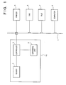
- Fig. 1 is a block diagram showing the arrangement of an information processing system according to an embodiment of the present invention.
- this system constitutes a LAN (local area network) connected to a communication line (network) 4.
- An image reading device 10 for reading an image a printer apparatus 5 for printing an image on a paper sheet, a facsimile device 6 for transmitting or receiving an image via a telephone line, a file apparatus 7 for storing an image or reading out the stored image, and a computer apparatus 8 for receiving an image and editing the received image are connected to the communication line 4.
- These apparatuses are respectively assigned with identifiers indicating the types of apparatuses, and address numbers on the network.
- the image reading device 10 is classified as an image input apparatus
- the printer apparatus 5 is classified as an image output apparatus
- the facsimile device 6, the file apparatus 7, and the computer apparatus 8 are classified as image input/output apparatuses.
- the image reading device 10, the facsimile device 6, the file apparatus 6, and the computer apparatus 8 are also image input apparatuses.
- the image reading device has a reader 1 for reading an original image, and converting the read image into image data, a controller 2 for controlling image data from the reader 1, and an operation unit 3 which is connected to the controller 2 and used to designate an output method of image data from the reader 1.
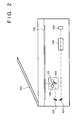
- Fig. 2 is a sectional view showing the arrangement of the reader 1.
- Originals stacked on an original feeder 101 are fed onto an original table glass surface 102 one by one.
- a lamp 103 of a scanner is turned on, and a scanner unit 104 moves to irradiate light onto the original.
- Light reflected by the original is transmitted through a lens 108 via mirrors 105, 106, and 107 in turn, and thereafter, is input to a CCD image sensor unit (to be referred to as a CCD hereinafter) 109.
- a CCD image sensor unit to be referred to as a CCD hereinafter
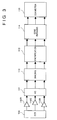
- Fig. 3 is a block diagram showing the signal processing arrangement of the reader 1.
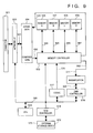
- Fig. 4 is a block diagram showing the controller 2 and the operation unit 3.
- Fig. 5 shows the layout of buttons on the panel of the operation unit 3.
- a printer switch 31 for designating an output destination of an image read by the reader 1 to the printer apparatus 5
- a FAX switch 32 for designating an output destination of an image read by the reader 1 to the facsimile device 6, a ten-key pad 33, and the like are arranged.
- all the apparatuses connected to the network have a table representing the network configuration, as shown in Fig. 6.
- This table is configured in the order of addresses assigned to the apparatuses on the network 4, and stores an identification name of an apparatus assigned to the corresponding address value, the type of the apparatus (such as a facsimile device, a printer apparatus, and the like), and the attribute of the apparatus in units of apparatuses.
- a method of outputting two images on two surfaces of a single output sheet will be explained below.
- an output sheet subjected to fixing in the fixing unit 207 is temporarily fed to the exhaust unit 208, the feed direction of the sheet is reversed, and the output sheet is then fed to a stacking unit 210 via a feed direction switching member 209.
- the stacking unit 210 the sheet on one surface of which an image is printed waits for a re-feed operation for printing an image on the other surface of the sheet.
- an original image is read in the same manner as in the above-mentioned process.
- the output sheet is fed from the re-feed stacking unit 210, two original images can be output onto two surfaces of a single output sheet.
- the facsimile device 6 is connected to the network 4 via a connector 400.
- a signal input via the connector 400 is input to a network interface circuit 409, and is then input to a memory controller 404 via a signal line 453.
- a signal 453 from the network interface circuit 409 is input to the memory controller 404, and the image data is stored in one of the memories A 405 to D 408 or in two cascade-connected memories under the control of the memory controller.
- a MODEM 414 has a function of modulating encoded information from the CODEC 411 or the hard disk connected to the SCSI controller 413 to transmit it onto a telephone line, and a function of demodulating information sent from an NCU 415.
- the demodulated encoded information is transferred to the CODEC 411 or the hard disk 420 connected to the SCSI controller 413 as encoded information.
- the NCU 415 is directly connected to the telephone line, and exchanges information with an exchange equipped in a telephone office in a predetermined protocol.
- Image data for each page is divided by an EOP (end of page) code.
- the EOP code is added upon creation of image data.
- the end of an image file is delimited by an EOF code.
- the EOF code is similarly added upon creation of image data.
- a network interface (network I/F) of the transmitting apparatus inserts an EOB (end of block) every 1 Mbytes in image data for one page.
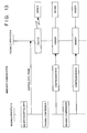
- a mode in which one frame includes further segmented image data is defined in addition to the above-mentioned 1-page transfer mode, half-page transfer mode, and 2-page transfer mode. More specifically, one frame can include image data for one line.
- a network interface of the transmitting apparatus inserts an EOL (end of line) at the end of each line upon transmission.
- step S152 If BR is small (0 ⁇ BR ⁇ 20), image data for two pages are transmitted to a destination apparatus in one frame in step S152. If one file includes 10 pages, the transfer operation of the file can be completed by transferring five frames. While the signal line is not too busy, even if long data is transferred, the influence (e.g., transmission of another apparatus is waited) on the entire system is small.
- step S156 the mode for sending image data for half a page in one frame to a destination apparatus is executed in step S156.
- the transfer operation of the file can be completed by transferring 20 frames.
- the half-page transfer mode since the data amount per frame is reduced, the busy rate of the system can be prevented from further increasing.
- a mode for sending data for one line in one frame may be executed.
- the immediate transmission is called "direct communication" in a normal facsimile device, and in this mode, an image read by a reading sensor is sent to a transmitter in units of lines without being stored in a memory.
- direct communication in a normal facsimile device, and in this mode, an image read by a reading sensor is sent to a transmitter in units of lines without being stored in a memory.
- the reading device 10 transfers data input by the user to the facsimile device 6 together with a control data frame. Upon reception of these data, the facsimile device 6 can prepare for reception of image data which follows, i.e., reception in units of lines.
- Compressed data on the network is input to the network interface circuit 409 via the connector 8 (Fig. 8) of the facsimile device 6.
- An output signal 453 from the network interface circuit 409 is stored in the memory B 406 under the control of the memory controller 404.
- the CPU 412 connects the memory B 406 of the memory controller 404 to the CPU bus 462.
- the CPU 412 sequentially reads out encoded data from the memory B 406, and transfers the readout data to the MODEM 414.
- the MODEM 414 modulates the encoded data, and transmits it onto the telephone line via the NCU.
- a user depresses a file switch 35 (Fig. 5). Then, the display 34 displays a message urging a user to designate a filing apparatus. Assume that the user designates the filing apparatus 7.
- the CPU 516 Upon completion of encoding by the CODEC 517, the CPU 516 connects the memory B 507 of the memory controller 510 to the CPU bus 560. The CPU 516 sequentially reads out the encoded data from the memory B 507, and transfers the readout data to the SCSI controller 519. The SCSI controller 519 stores encoded data 572 in the external storage device 573.
- the filing apparatus 7 can omit the compression processing, the filing apparatus 7 can share its performance with another processing, i.e., expansion processing of another image data requested by the computer apparatus 8.
- the CPU 516 instructs the interface 503 and the memory controller 510 to store the received data in the memory A 506 via the line 552.
- the CPU 516 connects the memories A 506 and B 507 of the memory controller 510 to the bus line 570 of the CODEC 517.
- the CODEC 517 reads out compressed data from the memory A 506, encodes the compressed data by the MR method, and writes the encoded data in the memory B 507.
- the CPU 516 connects the memory B 507 of the memory controller 510 to the CPU bus 560.
- the CPU 516 sequentially reads out the encoded data from the memory B 507, and transfers the readout data to the SCSI controller 519.
- the SCSI controller 519 stores encoded data 572 in the external storage device 573.
- the filing operation of data from the reading device 10 to the filing apparatus 7 has been exemplified.
- the output apparatus is not limited to the filing apparatus. Whether or not the compression methods of input and output apparatuses are the same is taken into account, and when the same compression method is adopted, the input apparatus performs compression to reduce the load on the output device; when different methods are adopted, the output apparatus performs compression to assure data compatibility.
Landscapes
- Engineering & Computer Science (AREA)
- Multimedia (AREA)
- Signal Processing (AREA)
- Facsimiles In General (AREA)
- Computer And Data Communications (AREA)
- Telephonic Communication Services (AREA)
Claims (16)
- Informationsverarbeitungssystem mit an ein Netzwerk (4) angeschlossenen ersten und zweiten Verarbeitungsvorrichtungen (5; 6; 7; 8; 10), wobei die erste Verarbeitungssvorrichtung (6; 7; 8; 10) eine Übertragung von Bilddaten zu dem Netzwerk ermöglicht, und die zweite Verarbeitungsvorrichtung (5; 6; 7; 8) ein Empfangen der Bilddaten von dem Netzwerk, wobei das System umfaßt:gekennzeichnet durcheine Steuereinrichtung (2) zum Steuern der Übertragung der Bilddaten von der ersten Verarbeitungsvorrichtung über das Netzwerk zu der zweiten Verarbeitungsvorrichtung,eine Erfassungseinrichtung zum Erfassen eines Kommunikationszustands des Netzwerks,wobei die Steuereinrichtung (2) in einer Vielzahl verschiedener Übertragungsbetriebsarten betrieben werden kann, wobei die Bilddaten in jeder von diesen als eine Vielzahl von Blökken mit in den verschiedenen Übertragungsbetriebsarten abweichender Blockgröße übertragen werden, so daß die Bilddaten in Blöcken übertragen werden, die in Abhängigkeit der Übertragungsbetriebsart jeweils aus einer Seite, einer Vielzahl von Seiten oder einem Teil einer Seite der Bilddaten bestehen, und wobei die Steuereinrichtung eine Übertragungsbetriebsartauswahleinrichtung aufweist zum Auswählen einer der verschiedenen Übertragungsbetriebsarten in Übereinstimmung mit dem durch die Erfassungseinrichtung erfaßten Kommunikationszustand des Netwerks.
- System nach Anspruch 1, wobei die Erfassungseinrichtung zum Erfassen des Dateverkehrs auf dem Netwzwerk und die Übertragungsbetriebsartauswahleinrichtung zum Auswählen der Übertragungsbetriebsart in Übereinstimmung mit dem erfaßten Datenverkehr auf dem Netzwerk ausgestaltet ist.
- System nach Anspruch 1 oder 2, wobei die Steuereinrichtung (2) in der ersten Verarbeitungsvorrichtung enthalten ist.
- System nach Patentanspruch 1, 2 oder 3, wobei die erste Verarbeitungsvorrichtung eine Bildleseeinrichiung (10) aufweist zum Lesen eines Bilds einer Vorlage, und zum Ausgeben der zu übertragenden Bilddaten.
- System nach einem der vorgenannten Ansprüche, wobei die Steuereinrichtung ausgestaltet ist zum Steuern eines Formats der von der ersten Vorrichtung zu der zweiten Vorrichtung zu übertragenden Bilddaten in Abhängigkeit einer Übereinstimmung zwischen Eigenschaften der durch die ersten Vorrichtung verarbeiteten Bilddaten und Eigenschaften der durch die zweite Vorrichtung verarbeiteten Bilddaten.
- System nach Anspruch 5, wobei die Steuereinrichtung ausgestaltet ist zum Steuern des Bilddatenformats in Abhängigkeit einer Übereinstimmung zwischen Kompressionsverfahren der ersten und zweiten Vorrichtung.
- System nach Anspruch 6, wobei die erste Vorrichtung eine erste Kompressionseinrichtung umfaßt, die zweite Vorrichtung eine zweite Kompressionseinrichtung, und die Steuereinrichtung ausgestaltet ist zum Deaktivieren der ersten Kompressionseinrichtung, wenn ein Kompressionsverfahren der ersten Kompressionseinrichtung von einem Kompressionsverfahren der zweiten Kompressionseinrichtung abweicht.
- System nach Anspruch 7, wobei die erste Vorrichtung eine erste Kompressionseinrichtung aufweist, die zweite Vorrichtung eine zweite Kompressionseinrichtung, und wobei die Steuereinrichtung ausgestaltet ist zum Aktivieren der ersten Kompressionseinrichtung, wenn ein Kompressionsverfahren der ersten Kompressionseinrichtung mit einem Kompressionsverfahren der zweiten Kompressionseinrichtung übereinstimmt.
- System nach einem der vorgenannten Ansprüche, wobei die zweite Vorrichtung einen Computer, ein Faksimileübertragungsmodem, einen Drucker oder eine Datei umfaßt.
- Informationsverarbeitungsvorrichtung zum Anschließen an ein Netzwerk, zum Austauschen von Bilddaten mit einer anderen Vorrichtung über das Netzwerk, mit:gekennzeichnet durcheiner Sendeeinrichtung (1) zum Senden von Bilddaten zu dem Netzwerk; undeiner Steuereinrichtung (2) zum Steuern einer Übertragung der Bilddaten zu dem Netzwerk durch die Sendeeinrichtung,eine Erfassungseinrichtung (3) zum Erfassen eines Kommunikationszustands des Netzwerks, wobei die Steuereinrichtung in einer Anzahl verschiedener Übertragungsbetriebsarten betreibbar ist, wobei in jeder von diesen die Bilddaten als eine Vielzahl von Blöcke mit in den verschiedenen Übertragungsbetriebsarten verschiedener Blockgröße übertragen werden, so daß die Bilddaten in Blöcken übertragen werden, die in Abhängigkeit der Übertragungsbetriebsart aus einer Seite, einer Vielzahl von Seiten oder einem Teil einer Seite der Bilddaten bestehen, und wobei die Steuereinrichtung eine Übertragungsbetriebsartauswähleinrichtung aufweist zum Auswählen einer der verschiedenen Übertragungsbetreibsarten in Übereinstimmung mit dem durch die Erfassungseinrichtung erfaßten Kommunikationszustand des Netzwerks.
- Vorrichtung nach Anspruch 10, wobei die Erfassungseinrichtung (3) zum Erfassen des Datenverkehrs auf dem Netzwerk ausgestaltet ist, und die Übertragungsbetriebsartauswähleinrichtung (2) zum Auswählen der Übertragungsbetriebsart in Übereinstimmung mit dem erfaßten Datenverkehr auf dem Netzwerk ausgestaltet ist.
- Vorrichtung nach Anspruch 10 oder 11, weiterhin umfassend eine Leseeinrichtung (1) zum Lesen eines Bilds einer Vorlage, und zum Ausgeben der zu übertragenden Bilddaten.
- Datenübertragungssteuerverfahren zum Steuern einer Übertragung von Bilddaten zwischen einer Vielzahl von Verarbeitungsvorrichtungen in einem Netzwerk, mit den Schritten: Erfassen eines Kommunikationszustands in dem Netzwerk; Steuern der Übertragung der Bilddaten in der Weise, daß die Bilddaten in einer von einer Anzahl verschiedener Übertragungsbetriebsarten übertragen werden, wobei die Bilddaten in jeder von diesen als eine Vielzahl von Blöcke mit in den verschiedenen Übertragungsbetriebsarten unterschiedlicher Blockgröße übertragen werden, so daß die Bilddaten in Blöcken übertragen werden, die in Abhängigkeit der Übertragungsbetriebsart aus einer Seite, einer Vielzahl von Seiten cder einem Teil einer Seite der Bilddaten bestehen; und Auswählen der für die Übertragung zu verwendenden einen aus den verschiedenen Übertragungsbetriebsarten in Übereinstimmung mit dem durch die Erfassungseinrichtung erfaßten Kommunikationszustand des Netzwerks.
- Verfahren nach Anspruch 13, wobei in dem Erfassungsschritt ein Datenverkehr in dem Netzwerk erfaßt wird, und die Übertragungsbetriebsart in Übereinstimmung mit dem erfaßten Datenverkehr ausgewählt wird.
- Verfahren nach Anspruch 13 oder 14, weiterhin umfassend die Schritte:Unterscheiden, ob Vorverarbeitungsfunktionen der Vorrichtungen, zwischen denen die Bilddaten zu übertragen sind, miteinander übereinstimmen, oder nicht; undDurchführen der Vorverarbeitung und Übertragen der vorverarbeiteten Daten, wenn die ersten und zweiten Vorverarbeitungsfunktionen übereinstimmen, und Übertragen der Daten vor der Vorverarbeitung, wenn die ersten und zweiten Vorverarbeitungsfunktionen voneinander abweichen.
- Verfahren nach Anspruch 15, wobei die ersten und zweiten Vorverarbeitungsfunktionen Kompressionsverarbeitungsfunktionen sind.
Applications Claiming Priority (2)
| Application Number | Priority Date | Filing Date | Title |
|---|---|---|---|
| JP6077216A JPH07288593A (ja) | 1994-04-15 | 1994-04-15 | 情報処理システム、情報処理装置およびデータ転送制御方法 |
| JP77216/94 | 1994-04-15 |
Publications (3)
| Publication Number | Publication Date |
|---|---|
| EP0677946A2 EP0677946A2 (de) | 1995-10-18 |
| EP0677946A3 EP0677946A3 (de) | 1996-04-17 |
| EP0677946B1 true EP0677946B1 (de) | 1999-01-07 |
Family
ID=13627654
Family Applications (1)
| Application Number | Title | Priority Date | Filing Date |
|---|---|---|---|
| EP95302506A Expired - Lifetime EP0677946B1 (de) | 1994-04-15 | 1995-04-13 | Datenübertragungssteuerungsverfahren und Informationsverarbeitungssystem, das dieses benutzt |
Country Status (4)
| Country | Link |
|---|---|
| US (1) | US5903722A (de) |
| EP (1) | EP0677946B1 (de) |
| JP (1) | JPH07288593A (de) |
| DE (1) | DE69507071T2 (de) |
Families Citing this family (2)
| Publication number | Priority date | Publication date | Assignee | Title |
|---|---|---|---|---|
| JP2013077294A (ja) * | 2011-09-16 | 2013-04-25 | Ricoh Co Ltd | 印刷装置および印刷装置の制御方法 |
| CN104657374A (zh) * | 2013-11-20 | 2015-05-27 | 富士通株式会社 | 信息处理装置、信息处理方法以及电子设备 |
Family Cites Families (13)
| Publication number | Priority date | Publication date | Assignee | Title |
|---|---|---|---|---|
| JPH0757002B2 (ja) * | 1982-10-05 | 1995-06-14 | キヤノン株式会社 | 画像処理装置 |
| US5023716A (en) * | 1988-03-28 | 1991-06-11 | Canon Kabushiki Kaisha | Image information signal transmitting system |
| US4993025A (en) * | 1989-11-21 | 1991-02-12 | Picker International, Inc. | High efficiency image data transfer network |
| JPH03254565A (ja) * | 1990-03-05 | 1991-11-13 | Ricoh Co Ltd | ファクシミリアダプタ装置 |
| US5274782A (en) * | 1990-08-27 | 1993-12-28 | International Business Machines Corporation | Method and apparatus for dynamic detection and routing of non-uniform traffic in parallel buffered multistage interconnection networks |
| EP0509524B1 (de) * | 1991-04-18 | 1999-11-10 | Canon Kabushiki Kaisha | Kommunikationssteuereinheit |
| JP3258347B2 (ja) * | 1991-08-14 | 2002-02-18 | キヤノン株式会社 | 画像形成装置 |
| JP3332398B2 (ja) * | 1991-11-07 | 2002-10-07 | キヤノン株式会社 | 画像処理装置及び画像処理方法 |
| JP3454855B2 (ja) * | 1993-02-01 | 2003-10-06 | 株式会社日立製作所 | ファクシミリサーバシステム |
| JP3461849B2 (ja) * | 1992-07-09 | 2003-10-27 | 株式会社リコー | ファクシミリ同報装置における割込み通信方法およびファクシミリ同報装置 |
| US5530907A (en) * | 1993-08-23 | 1996-06-25 | Tcsi Corporation | Modular networked image processing system and method therefor |
| KR970009698B1 (ko) * | 1994-07-07 | 1997-06-17 | 엘지산전 주식회사 | 피엘씨의 통신 파라메터 설정 방법 |
| US5664105A (en) * | 1994-10-04 | 1997-09-02 | Fluke Corporation | Method and apparatus for network analysis |
-
1994
- 1994-04-15 JP JP6077216A patent/JPH07288593A/ja active Pending
-
1995
- 1995-04-13 EP EP95302506A patent/EP0677946B1/de not_active Expired - Lifetime
- 1995-04-13 DE DE69507071T patent/DE69507071T2/de not_active Expired - Lifetime
- 1995-04-14 US US08/422,164 patent/US5903722A/en not_active Expired - Lifetime
Also Published As
| Publication number | Publication date |
|---|---|
| EP0677946A3 (de) | 1996-04-17 |
| DE69507071T2 (de) | 1999-06-10 |
| DE69507071D1 (de) | 1999-02-18 |
| EP0677946A2 (de) | 1995-10-18 |
| US5903722A (en) | 1999-05-11 |
| JPH07288593A (ja) | 1995-10-31 |
Similar Documents
| Publication | Publication Date | Title |
|---|---|---|
| US5428458A (en) | Image communicating apparatus | |
| US20020008882A1 (en) | Image processing method and apparatus | |
| EP0618716B1 (de) | Bildverarbeitungsgerät mit mehreren Funktionen | |
| US5867638A (en) | Information processing system | |
| EP0677946B1 (de) | Datenübertragungssteuerungsverfahren und Informationsverarbeitungssystem, das dieses benutzt | |
| US6041199A (en) | Image formation apparatus with sheet stacking control feature | |
| JPH07298016A (ja) | 画像形成装置 | |
| JPH06340151A (ja) | 画像出力装置 | |
| JP2790820B2 (ja) | ファクシミリ通信方式 | |
| JP3236173B2 (ja) | データ通信装置 | |
| JPH04181859A (ja) | フアクシミリサーバ装置 | |
| JPH0888761A (ja) | 画像読取装置および画像読取方法 | |
| JPH06152854A (ja) | 画像形成装置 | |
| JPH07297965A (ja) | デジタル複写機及び情報処理システムと前記複写機における情報表示方法 | |
| JPH0884229A (ja) | 画像形成装置 | |
| JPH0774964A (ja) | 画像処理装置 | |
| JPH08289069A (ja) | 画像通信及び画像蓄積装置 | |
| JPH089121A (ja) | 画像形成装置 | |
| JPH08287233A (ja) | 画像通信及び画像蓄積装置 | |
| JPH06311358A (ja) | 画像処理装置 | |
| JPH08167975A (ja) | 画像処理装置 | |
| JPH07264363A (ja) | 画像形成装置 | |
| JPH08237400A (ja) | 受信画像記録装置 | |
| JPH08289070A (ja) | 画像通信及び画像蓄積装置 | |
| JPH05318961A (ja) | 画像形成装置 |
Legal Events
| Date | Code | Title | Description |
|---|---|---|---|
| PUAI | Public reference made under article 153(3) epc to a published international application that has entered the european phase |
Free format text: ORIGINAL CODE: 0009012 |
|
| AK | Designated contracting states |
Kind code of ref document: A2 Designated state(s): DE FR GB IT |
|
| PUAL | Search report despatched |
Free format text: ORIGINAL CODE: 0009013 |
|
| AK | Designated contracting states |
Kind code of ref document: A3 Designated state(s): DE FR GB IT |
|
| 17P | Request for examination filed |
Effective date: 19960829 |
|
| 17Q | First examination report despatched |
Effective date: 19970410 |
|
| GRAG | Despatch of communication of intention to grant |
Free format text: ORIGINAL CODE: EPIDOS AGRA |
|
| GRAG | Despatch of communication of intention to grant |
Free format text: ORIGINAL CODE: EPIDOS AGRA |
|
| GRAH | Despatch of communication of intention to grant a patent |
Free format text: ORIGINAL CODE: EPIDOS IGRA |
|
| GRAH | Despatch of communication of intention to grant a patent |
Free format text: ORIGINAL CODE: EPIDOS IGRA |
|
| GRAA | (expected) grant |
Free format text: ORIGINAL CODE: 0009210 |
|
| AK | Designated contracting states |
Kind code of ref document: B1 Designated state(s): DE FR GB IT |
|
| REF | Corresponds to: |
Ref document number: 69507071 Country of ref document: DE Date of ref document: 19990218 |
|
| ET | Fr: translation filed | ||
| ITF | It: translation for a ep patent filed | ||
| PLBE | No opposition filed within time limit |
Free format text: ORIGINAL CODE: 0009261 |
|
| STAA | Information on the status of an ep patent application or granted ep patent |
Free format text: STATUS: NO OPPOSITION FILED WITHIN TIME LIMIT |
|
| 26N | No opposition filed | ||
| REG | Reference to a national code |
Ref country code: GB Ref legal event code: IF02 |
|
| PGFP | Annual fee paid to national office [announced via postgrant information from national office to epo] |
Ref country code: IT Payment date: 20090420 Year of fee payment: 15 Ref country code: FR Payment date: 20090424 Year of fee payment: 15 |
|
| REG | Reference to a national code |
Ref country code: FR Ref legal event code: ST Effective date: 20101230 |
|
| PG25 | Lapsed in a contracting state [announced via postgrant information from national office to epo] |
Ref country code: IT Free format text: LAPSE BECAUSE OF NON-PAYMENT OF DUE FEES Effective date: 20100413 |
|
| PG25 | Lapsed in a contracting state [announced via postgrant information from national office to epo] |
Ref country code: FR Free format text: LAPSE BECAUSE OF NON-PAYMENT OF DUE FEES Effective date: 20100430 |
|
| PGFP | Annual fee paid to national office [announced via postgrant information from national office to epo] |
Ref country code: DE Payment date: 20130430 Year of fee payment: 19 Ref country code: GB Payment date: 20130418 Year of fee payment: 19 |
|
| REG | Reference to a national code |
Ref country code: DE Ref legal event code: R119 Ref document number: 69507071 Country of ref document: DE |
|
| GBPC | Gb: european patent ceased through non-payment of renewal fee |
Effective date: 20140413 |
|
| REG | Reference to a national code |
Ref country code: DE Ref legal event code: R119 Ref document number: 69507071 Country of ref document: DE Effective date: 20141101 |
|
| PG25 | Lapsed in a contracting state [announced via postgrant information from national office to epo] |
Ref country code: DE Free format text: LAPSE BECAUSE OF NON-PAYMENT OF DUE FEES Effective date: 20141101 Ref country code: GB Free format text: LAPSE BECAUSE OF NON-PAYMENT OF DUE FEES Effective date: 20140413 |