EP0678131B1 - Asphalt mischtrommel mit temperaturkontrolle - Google Patents
Asphalt mischtrommel mit temperaturkontrolle Download PDFInfo
- Publication number
- EP0678131B1 EP0678131B1 EP93907569A EP93907569A EP0678131B1 EP 0678131 B1 EP0678131 B1 EP 0678131B1 EP 93907569 A EP93907569 A EP 93907569A EP 93907569 A EP93907569 A EP 93907569A EP 0678131 B1 EP0678131 B1 EP 0678131B1
- Authority
- EP
- European Patent Office
- Prior art keywords
- drum
- aggregate
- sleeve
- enclosure
- interior
- Prior art date
- Legal status (The legal status is an assumption and is not a legal conclusion. Google has not performed a legal analysis and makes no representation as to the accuracy of the status listed.)
- Expired - Lifetime
Links
- 239000010426 asphalt Substances 0.000 claims abstract description 28
- 239000007788 liquid Substances 0.000 claims description 17
- 238000010438 heat treatment Methods 0.000 claims description 7
- 230000005484 gravity Effects 0.000 claims description 4
- 239000000654 additive Substances 0.000 claims description 3
- 230000000996 additive effect Effects 0.000 claims description 3
- 238000001035 drying Methods 0.000 claims description 2
- 239000000203 mixture Substances 0.000 abstract description 12
- 238000010924 continuous production Methods 0.000 abstract description 2
- 239000007789 gas Substances 0.000 description 5
- GUJOJGAPFQRJSV-UHFFFAOYSA-N dialuminum;dioxosilane;oxygen(2-);hydrate Chemical compound O.[O-2].[O-2].[O-2].[Al+3].[Al+3].O=[Si]=O.O=[Si]=O.O=[Si]=O.O=[Si]=O GUJOJGAPFQRJSV-UHFFFAOYSA-N 0.000 description 4
- 230000010006 flight Effects 0.000 description 3
- 239000000463 material Substances 0.000 description 3
- 238000007789 sealing Methods 0.000 description 3
- 239000004575 stone Substances 0.000 description 3
- 238000001914 filtration Methods 0.000 description 2
- 235000008733 Citrus aurantifolia Nutrition 0.000 description 1
- 235000011941 Tilia x europaea Nutrition 0.000 description 1
- 238000005299 abrasion Methods 0.000 description 1
- 239000000428 dust Substances 0.000 description 1
- 239000011152 fibreglass Substances 0.000 description 1
- 239000000446 fuel Substances 0.000 description 1
- 238000009413 insulation Methods 0.000 description 1
- 239000004571 lime Substances 0.000 description 1
- 238000005259 measurement Methods 0.000 description 1
- 230000001681 protective effect Effects 0.000 description 1
Images

Classifications
-
- E—FIXED CONSTRUCTIONS
- E01—CONSTRUCTION OF ROADS, RAILWAYS, OR BRIDGES
- E01C—CONSTRUCTION OF, OR SURFACES FOR, ROADS, SPORTS GROUNDS, OR THE LIKE; MACHINES OR AUXILIARY TOOLS FOR CONSTRUCTION OR REPAIR
- E01C19/00—Machines, tools or auxiliary devices for preparing or distributing paving materials, for working the placed materials, or for forming, consolidating, or finishing the paving
- E01C19/02—Machines, tools or auxiliary devices for preparing or distributing paving materials, for working the placed materials, or for forming, consolidating, or finishing the paving for preparing the materials
- E01C19/10—Apparatus or plants for premixing or precoating aggregate or fillers with non-hydraulic binders, e.g. with bitumen, with resins, i.e. producing mixtures or coating aggregates otherwise than by penetrating or surface dressing; Apparatus for premixing non-hydraulic mixtures prior to placing or for reconditioning salvaged non-hydraulic compositions
- E01C19/1013—Plant characterised by the mode of operation or the construction of the mixing apparatus; Mixing apparatus
- E01C19/1027—Mixing in a rotary receptacle
- E01C19/1036—Mixing in a rotary receptacle for in-plant recycling or for reprocessing, e.g. adapted to receive and reprocess an addition of salvaged material, adapted to reheat and remix cooled-down batches
-
- E—FIXED CONSTRUCTIONS
- E01—CONSTRUCTION OF ROADS, RAILWAYS, OR BRIDGES
- E01C—CONSTRUCTION OF, OR SURFACES FOR, ROADS, SPORTS GROUNDS, OR THE LIKE; MACHINES OR AUXILIARY TOOLS FOR CONSTRUCTION OR REPAIR
- E01C19/00—Machines, tools or auxiliary devices for preparing or distributing paving materials, for working the placed materials, or for forming, consolidating, or finishing the paving
- E01C19/02—Machines, tools or auxiliary devices for preparing or distributing paving materials, for working the placed materials, or for forming, consolidating, or finishing the paving for preparing the materials
- E01C19/10—Apparatus or plants for premixing or precoating aggregate or fillers with non-hydraulic binders, e.g. with bitumen, with resins, i.e. producing mixtures or coating aggregates otherwise than by penetrating or surface dressing; Apparatus for premixing non-hydraulic mixtures prior to placing or for reconditioning salvaged non-hydraulic compositions
- E01C19/1059—Controlling the operations; Devices solely for supplying or proportioning the ingredients
- E01C19/1063—Controlling the operations
-
- E—FIXED CONSTRUCTIONS
- E01—CONSTRUCTION OF ROADS, RAILWAYS, OR BRIDGES
- E01C—CONSTRUCTION OF, OR SURFACES FOR, ROADS, SPORTS GROUNDS, OR THE LIKE; MACHINES OR AUXILIARY TOOLS FOR CONSTRUCTION OR REPAIR
- E01C19/00—Machines, tools or auxiliary devices for preparing or distributing paving materials, for working the placed materials, or for forming, consolidating, or finishing the paving
- E01C19/02—Machines, tools or auxiliary devices for preparing or distributing paving materials, for working the placed materials, or for forming, consolidating, or finishing the paving for preparing the materials
- E01C19/10—Apparatus or plants for premixing or precoating aggregate or fillers with non-hydraulic binders, e.g. with bitumen, with resins, i.e. producing mixtures or coating aggregates otherwise than by penetrating or surface dressing; Apparatus for premixing non-hydraulic mixtures prior to placing or for reconditioning salvaged non-hydraulic compositions
- E01C2019/1081—Details not otherwise provided for
- E01C2019/1086—Mixing containers having concentric drums
-
- E—FIXED CONSTRUCTIONS
- E01—CONSTRUCTION OF ROADS, RAILWAYS, OR BRIDGES
- E01C—CONSTRUCTION OF, OR SURFACES FOR, ROADS, SPORTS GROUNDS, OR THE LIKE; MACHINES OR AUXILIARY TOOLS FOR CONSTRUCTION OR REPAIR
- E01C19/00—Machines, tools or auxiliary devices for preparing or distributing paving materials, for working the placed materials, or for forming, consolidating, or finishing the paving
- E01C19/02—Machines, tools or auxiliary devices for preparing or distributing paving materials, for working the placed materials, or for forming, consolidating, or finishing the paving for preparing the materials
- E01C19/10—Apparatus or plants for premixing or precoating aggregate or fillers with non-hydraulic binders, e.g. with bitumen, with resins, i.e. producing mixtures or coating aggregates otherwise than by penetrating or surface dressing; Apparatus for premixing non-hydraulic mixtures prior to placing or for reconditioning salvaged non-hydraulic compositions
- E01C2019/1081—Details not otherwise provided for
- E01C2019/109—Mixing containers having a counter flow drum, i.e. the flow of material is opposite to the gas flow
Definitions
- the present invention relates to an asphalt drum mixer of the type employed to continuously heat and dry stone aggregate, while mixing the heated and dried aggregate with liquid asphalt to produce asphalt paving composition.
- the aggregate drying and mixing steps are carried out in a rotating drum which is inclined from the horizontal.
- the virgin aggregate is introduced into the upper end of the drum, and an outlet is provided adjacent the lower end of the drum for withdrawing the heated and dried aggregate.
- a burner is mounted adjacent one end of the drum so as to create a heated gas stream which moves through the drum, either parallel to or counter to the flow of the moving aggregate.
- liquid asphalt is commonly introduced into the interior of the drum at a location midway along its length, so that the asphalt becomes mixed with the cascading aggregate and produces a paving composition which exits from the outlet.
- a fixed sleeve surrounds the lower portion of the rotating drum so that the heated and dried aggregate is discharged into the annular chamber which is formed between the drum and sleeve.
- an inlet is provided in the sleeve by which RAP may be introduced into the annular chamber, and another inlet is provided to introduce liquid asphalt into the annular chamber.
- the drum mounts mixing blades which move through the annular chamber to mix the materials and cause them to move longitudinally to the discharge outlet of the sleeve.
- the temperature of the virgin aggregate must be carefully controlled to ensure a predetermined final temperature of the asphalt composition after the addition of the liquid asphalt and RAP, if used, and under varying operating conditions.
- thermocouple is mounted adjacent the mix outflow part of a drum mixer to measure the temperature of the aggregate mix flowing out the discharge chute of the drum mixer.
- a controller combines signals form this thermocouple with signals from other sensors and transmits output signals to a damper.
- the temperature sensor must be shielded from the radiant heat of the burner in order to accurately measure the temperature of the aggregate. Also, the sensor must be exposed to a flow of representative aggregate, yet not be exposed to the full fury of the mixing zone where it can be quickly destroyed by abrasion and the forces imparted by the mixing blades. Heretofore, these requirements have not been fully met.
- a drum mixer which comprises a fixedly mounted cylindrical sleeve disposed in a generally horizontal orientation and defining opposite side wall portions.
- the aggregate is heated and conveyed longitudinally through the interior of said sleeve, and means are provided for sensing the temperature of the heated aggregate as it is conveyed through the interior of said sleeve.
- This sensing means comprises an opening in one of the side wall portions of said sleeve, and a box-like enclosure mounted on the outside of the sleeve so as to cover the opening.
- the enclosure includes an outer wall, a top wall, and opposite side walls, and the outer wall is disposed generally along a tangent to the one side wall portion of the sleeve when viewed in vertical cross section, and so that a portion of the heated aggregate which is being conveyed through the sleeve is adapted to be conveyed into the enclosure through the opening and then fall by gravity along the outer wall and back through the opening and into the interior of the sleeve.
- the sensing means further includes sensor mounting means for mounting at least one temperature sensor within the enclosure so as to sense the temperature of the aggregate which is conveyed into and then falls from the enclosure.
- the means for heating the aggregate comprises an elongate hollow drum disposed coaxially within the sleeve so as to define an annular mixing chamber between the drum and sleeve.
- the drum is mounted for rotation about its axis, and the common axis of the drum and sleeve is inclined somewhat from the horizontal.
- Aggregate is adapted to enter the upper end of the drum, and upon rotation of the drum, the aggregate moves in a cascading fashion toward the lower end of the drum where it drops into the annular mixing chamber.
- a burner is disposed adjacent the lower end of the drum, so that the aggregate moving through the drum moves counter to the direction of gas flow through the drum.
- the sleeve has a lower end which overlies the lower outlet end of the drum, and mixing blades are mounted to the exterior of the drum so as to be positioned within the annular chamber for mixing the aggregate received therein upon rotation of the drum and moving the aggregate toward the discharge opening of the sleeve, and while continuously conveying a representative portion of the moving aggregate into the enclosure where its temperature may be sensed.
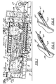
- Figure 1 illustrates a drum mixer 10 in accordance with one preferred embodiment of the present invention.
- the mixer comprises an elongate hollow drum 12 defining a central axis 13, and with the drum being mounted for rotation about the central axis.
- the central axis is inclined with respect to the horizontal 14 so as to define an upper end 16 and a lower end 17 of the drum.
- the drum 12 is rotatably mounted on a frame 18 by means of bearings 19 mounted to the frame which engage races 20 which are mounted about the circumference of the drum.
- a motor 21 rotatably drives the drum by engagement with a circumferential gear 22, and as further illustrated in the above noted patents to Brock, the disclosures of which are incorporated herein by reference.
- An aggregate inlet chute 23 is positioned adjacent the upper end of the drum for introducing stone aggregate or the like into the interior of the drum.
- the inlet chute 23 is preferably provided with an air sealing flop gate (not shown) of conventional design.
- a plurality of outlet openings 24 are formed about the periphery of the drum at the lower end thereof for withdrawing the heated aggregate from the interior of the drum in the manner further described below.
- a plurality of flights or vanes 26 are mounted on the inside of the drum, for lifting the aggregate and dropping the same through the interior of the mixer as it is rotated.
- the flights 26 may be of different configurations in different portions of the drum, as is conventional.
- the drum mixer 10 further includes a burner 27 which is mounted in an enclosure 28 at the lower end of the drum for directing a high temperature flame into the interior of the drum.
- the burner 27 is of conventional design, and it includes a blower 29 which charges a mixture of fuel and air into the burner, where it is ignited to produce a flame for heating the interior of the drum.
- the enclosure 28 may include mufflers of conventional design to provide relatively quiet operation.
- An exhaust duct 30 is positioned at the upper end of the drum, which may include an exhaust fan (not shown) for exhausting the heated gas from the drum and so that the heated gas flows through the drum to heat the cascading aggregate. The exhaust air flow is ducted to a conventional filtering baghouse or other dust collector.
- the drum mixer 10 further comprises a fixed sleeve 32 which is mounted coaxially about a portion of the length of the drum 12 adjacent the lower end 17 thereof, and so that the drum and sleeve define an annular chamber 34 therebetween.
- the sleeve 32 is thus similarly inclined to the horizontal, so as to define an upper end 35 and a lower end 36.
- the sleeve also includes annular shoulders 37, 38 at each end thereof to close the annular chamber 34 between the drum and the sleeve, and the lower end 36 of the sleeve 32 overlies the outlet openings 24 of the drum 12 so that the outlet openings 24 open into the annular chamber 34.
- the sleeve 32 further includes a discharge opening 40 adjacent the upper end thereof, which preferably also includes an air sealing flop gate (not shown).
- a plurality of paddle like flights or mixing blades 42 are mounted on the outer circumference of the drum 12 along the portion of the drum received within the sleeve 32.
- the blades 42 are configured and angled such that as the blades traverse the annular chamber 34, they engage the aggregate in the annular chamber and move the aggregate toward the discharge opening 40 of the sleeve, while causing the aggregate to be mixed.
- a liquid asphalt supply pipe 44 ( Figure 1) communicates with the annular chamber 34 for introducing liquid asphalt into the chamber so as to be mixed with the aggregate therein.
- an inlet 45 positioned adjacent the lower end of the sleeve permits an additive, such as recyclable asphalt pavement, to be introduced into the annular chamber and so as to be mixed with the aggregate and the liquid asphalt therein.
- the inlet 45 includes an air sealing flop gate 46 as seen in Figure 2. The resulting asphalt paving composition is discharged through the discharge opening 40 of the sleeve.
- a further inlet 48 is provided intermediate the length of the sleeve for permitting another additive, such as lime, to be introduced into the annular chamber, and so as to be mixed with the other materials in the chamber.
- another additive such as lime
- the outer sleeve of the drum mixer is insulated by a layer of fiberglass insulation 50, and the inside surface of the sleeve is preferably covered by a protective lining material 52, as best seen in Figure 3.
- the sensing means comprises an opening 54 ( Figure 3) in one of the side wall portions of the sleeve, and a box-like enclosure 55 is mounted on the outside of the sleeve so as to cover the opening 54. More particularly, the enclosure 55 includes an outer wall 56, a top wall 58, and opposite side walls 59, 60.
- the outer wall 56 is disposed generally along a tangent to the side wall portion of the sleeve when viewed in vertical cross-section (i.e., Figure 3) and so that a portion of the heated aggregate which is being conveyed through the annular chamber 34 by the blades 42 is adapted to be conveyed into the enclosure 55 through the opening 54, and then fall by gravity along the outer wall 56 and back through the opening 54 and into the interior of the annular chamber 34.
- the top wall 58 of the enclosure is mounted to the sleeve by means of a hinge 62, to facilitate access to the interior of the enclosure.
- the top wall 58 lies in a plane which includes the central axis 13, and the opposite side walls 59, 60 lie in parallel planes which are each inclined at an angle A of about 60° from the central axis 13 when viewed in side elevation (note Figure 4).
- Each of the outer wall 56, and opposite sides 59, 60 mount a sensor mounting tube 64 for mounting one or more temperature sensors within the enclosure.
- Each tube 64 in turn mounts an internally threaded sleeve 65, for receiving either the sensor 66 as seen in Figure 5, or a closure plug 67 as seen in Figure 6.
- one, two, or three temperature sensors 66 may be positioned to extend through respective tubes 64 and be positioned at a location within the enclosure so as to sense the temperature of the aggregate which enters and then falls from the enclosure.
- the aggregate In operation, the aggregate is continuously introduced through the inlet chute 23 into the upper end 16 of the rotating drum 12, and so that the aggregate cascades through the interior of the drum and moves toward the outlet openings 24 at the lower end 17. Also, with the burner 27 in operation, heated gasses flow through the length of the drum and exhaust through the outlet duct 30 to a filtering baghouse or the like.
- the heated aggregate falls through the openings 24 at the lower end of the drum and into the annular chamber 34 defined by the sleeve 32.
- RAP may if desired be introduced into the annular chamber through the inlet 45, which is downstream of the opening 54 in the side wall portion of the sleeve, and liquid asphalt is introduced into the annular chamber at the supply pipe 44 which is located downstream of the inlet 45 at which the RAP is introduced.
- the rotating blades 42 engage the aggregate as it falls into the annular chamber through the openings 24, and convey it toward the discharge opening 40, while mixing the aggregate with the liquid asphalt and RAP, if used.
- the rotation of the blades 42 causes a portion of the aggregate to be continuously thrown through the opening 54 and into the enclosure 55.
- the aggregate falls by gravity along the outer wall 56 and past the temperature sensors 66, and back into the annular chamber 34. Since the blades 42 also move the aggregate longitudinally, fresh samples of the aggregate are continuously thrown into the enclosure 55, to thereby continuously provide a representative sample to the sensors 66.
- the output signals of the sensors 66 are fed to a burner computer control as illustrated schematically at 70 in Figure 2, for controlling the flame intensity of the burner 27 and so as to permit the temperature of the aggregate to be closely controlled under varying operating conditions. More particularly, the final temperature of the asphalt composition being produced is established, and checked by a temperature sensor (not shown) mounted in the discharge opening 40.
- the computer control 70 can determine the required temperature for the virgin aggregate based on the desired final temperature and the heat lost or absorbed by the RAP. Any deviation in temperature can be quickly corrected by adjusting the intensity of the burner 27, due to its close proximity to the measuring point.
Landscapes
- Engineering & Computer Science (AREA)
- Architecture (AREA)
- Civil Engineering (AREA)
- Structural Engineering (AREA)
- Road Paving Machines (AREA)
Claims (12)
- Mischtrommel (10) zum Erhitzen und Trocknen eines Stoffgemisches, umfassend einen Zylinder (32), der im wesentlichen in horizontaler Richtung angeordnet und durch gegenüberliegende Teilwände begrenzt ist, Mittel (42) zur Förderung des erhitzten Stoffgemisches in Längsrichtung durch das Innere dieses Zylinders und Mittel zur Feststellung der Temperatur des erhitzten Stoffgemisches während es durch das Innere des Zylinders hindurchgefördert wird, dadurch gekennzeichnet, daß dieser Zylinder (32) durch eine fest montierte Röhre gebildet ist und daß die Mittel zur Temperaturfeststellung umfassena) eine Öffnung (54) in einer der Seitenwandteile,b) ein kastenartiges Gehäuse (55), das an der Außenseite der Röhre angeordnet ist, um die Öffnung zu überdecken, wobei das Gehäuse eine Außenwand (56), eine obere Wand (58) und gegenüberliegende Seitenwände (59, 60) aufweist und wobei die Außenwand im allgemeinen entlang einer Tangente zu der Seitenwand der Röhre angeordnet ist, wenn man den Querschnitt betrachtet, so daß ein Teil des erhitzten Gemisches, welches durch die Röhre hindurchgefördert wird, in dieses Gehäuse (55) durch die Öffnung (54) förderbar ist und dann aufgrund von Schwerkraft entlang der Außenwand (56) fällt und dann durch die Öffnung (54) in das Innere der Röhre zurückfällt,c) ein Temperatursensor (66) für die Feststellung der Temperatur des Gemisches, welches in das Gehäuse hinein und dann aus diesem wieder herausfällt, undd) Sensorbefestigungsmittel (64) für die Befestigung des Temperatursensors innerhalb des Gehäuses.
- Mischtrommel nach Anspruch 1, dadurch gekennzeichnet, daß die Sensorbefestigungsmittel zumindest eine Befestigungshülse (64) umfassen, die sich durch eine der Wände des Gehäuses erstrecken, derart, daß sich der Temperatursensor durch die Hülse hindurch in das Gehäuse hinein erstreckt.
- Mischtrommel nach Anspruch 1, dadurch gekennzeichnet, daß Mittel (27) zum Erhitzen des Gemisches und Mittel (12, 24) zur Förderung des Gemisches in das Innere der Röhre (32) vorgesehen sind.
- Mischtrommel nach Anspruch 3, dadurch gekennzeichnet, daß Mittel (70) zur Regelung der Heizmittel (27) in Abhängigkeit von der durch den Sensor (66) festgestellten Temperatur vorgesehen sind, um die Temperatur des Gemisches in engen Grenzen zu regeln.
- Mischtrommel nach Anspruch 4, dadurch gekennzeichnet, daß Mittel (34) für die Einführung von flüssigem Asphalt in das Innere der Röhre (32) an einer stromabwärts der Öffnung gelegenen Stelle vorgesehen sind, so daß der flüssige Asphalt mit dem erhitzten Gemisch, welches hindurchgefördert wird, gemischt wird.
- Mischtrommel nach Anspruch 1, dadurch gekennzeichnet, daß die längliche hohle Trommel (12) innerhalb der Röhre angeordnet ist und eine zentrale Achse (13) bestimmt, daß Mittel (18, 19) zur drehbaren Lagerung der Trommel um die zentrale Achse vorgesehen sind, wobei diese zentrale Achse in bezug auf die Horizontale geneigt ist, derart, daß ein oberes Ende (16) und ein unteres Ende (17) der Trommel bestimmt sind,daß Gemischeinlaßmittel (23) in der Nähe des oberen Endes der Trommel für die Einführung des Gemisches in das Innere der Trommel vorgesehen sind,daß Gemischauslaßmittel (24) in der Nähe des unteren Endes der Trommel für das Abziehen des Gemisches aus dem Inneren der Trommel vorgesehen sind,daß Mittel (21) zur Drehung der Trommel um die zentrale Achse vorgesehen sind, derart, daß das Gemisch, welches durch das Einlaßmittel eingeführt ist, in Kaskaden durch das Innere der Trommel und zu dem Auslaßmittel bewegt wird,daß Heizmittel (27) in der Nähe des unteren Endes der Trommel vorgesehen sind, um erhitztes Gas in das Innere der Trommel einzuführen,daß Abgasauslaßmittel (30) in der Nähe des oberen Endes der Trommel für das Auslassen des erhitzten Gases vorgesehen sind, so daß das erhitzte Gas durch die Trommel und durch das in Kaskaden sich bewegende Gemisch hindurchströmt,daß die Röhre (32) koaxial um einen Teil der Länge der Trommel in der Nähe des unteren Endes vorgesehen ist, derart, daß eine Ringkammer (34) zwischen der Trommel und der Röhre gebildet ist, wobei die Röhre ein unteres Ende (36), welches das Auslaßmittei der Trommel übergreift, und ein oberes Ende (35) aufweist, das zwischen den Enden der Trommel angeordnet ist, wobei das Auslaßmittel der Trommel in die Ringkammer mündet, um so das erhitzte und getrocknete Gemisch darin aufzunehmen, und daß Fördermittel, die Mischflügel (42) aufweisen, auf der Außenseite der Trommel angeordnet sind, so daß sie sich innerhalb der Ringkammer für das Mischen des darin aufgenommenen Gemisches bei Drehung der Trommel und für das Bewegen des Gemisches in Richtung auf die Austragsöffnung der Röhre befinden.
- Mischtrommel nach Anspruch 6, dadurch gekennzeichnet, daß Mittel (70) für die Regelung der Heizmittel in Abhängigkeit der durch den Sensor festgestellten Temperatur vorgesehen sind, um hierdurch die Temperatur des Gemisches in engen Grenzen zu regeln.
- Mischtrommel nach Anspruch 7, dadurch gekennzeichnet, daß Mittel (44) für die Einführung von flüssigem Asphalt in die Ringkammer an einer Stelle stromabwärts der Öffnung vorgesehen sind, so daß der flüssige Asphalt mit dem hindurchgeförderten Gemisch vermischt wird.
- Mischtrommel nach Anspruch 8, dadurch gekennzeichnet, daß Mittel (48) in der Nähe des unteren Endes der Röhre für die Einführung eines Additives in die Ringkammer vorgesehen sind, das mit dem Gemisch und dem flüssigen Asphalt in dieser ringförmigen Kammer gemischt wird.
- Mischtrommel nach Anspruch 8, dadurch gekennzeichnet, daß die Deckenwand des Gehäuses klappbar an der Röhre angeordnet ist, um den Zugang in das Innere dieses Gehäuses zu erleichtern.
- Mischtrommel nach Anspruch 8, dadurch gekennzeichnet, daß die Sensorhaltemittel eine Vielzahl von Sensorhaltehülsen umfassen, welche sich durch eine der Wände des Gehäuses erstrecken, um so eine Anzahl dieser Temperatursensoren in dem Gehäuse anordnen zu können.
- Mischtrommel nach Anspruch 8, dadurch gekennzeichnet, daß die Deckenwand des Gehäuses in einer Ebene liegt, welche die zentrale Achse einschließt und die gegenüberliegen' den Seitenwände des Gehäuses in parallelen Ebenen liegen, welche jeweils um einen Winkel von ungefähr 60° gegenüber der Zentralachse geneigt sind, wenn man die Seitenansicht betrachtet.
Applications Claiming Priority (3)
| Application Number | Priority Date | Filing Date | Title |
|---|---|---|---|
| US08/000,978 US5320426A (en) | 1993-01-06 | 1993-01-06 | Asphalt drum mixer having temperature sensor enclosure |
| US978 | 1993-01-06 | ||
| PCT/US1993/002453 WO1994016146A1 (en) | 1993-01-06 | 1993-03-15 | Asphalt drum mixer with temperature control |
Publications (2)
| Publication Number | Publication Date |
|---|---|
| EP0678131A1 EP0678131A1 (de) | 1995-10-25 |
| EP0678131B1 true EP0678131B1 (de) | 1997-12-03 |
Family
ID=21693803
Family Applications (1)
| Application Number | Title | Priority Date | Filing Date |
|---|---|---|---|
| EP93907569A Expired - Lifetime EP0678131B1 (de) | 1993-01-06 | 1993-03-15 | Asphalt mischtrommel mit temperaturkontrolle |
Country Status (7)
| Country | Link |
|---|---|
| US (1) | US5320426A (de) |
| EP (1) | EP0678131B1 (de) |
| JP (1) | JP3220751B2 (de) |
| AU (1) | AU3812793A (de) |
| CA (1) | CA2152084C (de) |
| DE (1) | DE69315595T2 (de) |
| WO (1) | WO1994016146A1 (de) |
Families Citing this family (11)
| Publication number | Priority date | Publication date | Assignee | Title |
|---|---|---|---|---|
| US5513443A (en) * | 1995-01-13 | 1996-05-07 | Asphalt Drum Mixers, Inc. | Dryer for aggregate and reclaimed asphalt products |
| US5772317A (en) * | 1996-08-27 | 1998-06-30 | Gencor Industries, Inc. | Counterflow drum mixer for making asphaltic concrete and methods of operation |
| US6196710B1 (en) | 1999-11-26 | 2001-03-06 | Astec Industries, Inc. | Dust distributor for asphalt mixing machine |
| US7300225B2 (en) * | 2005-03-14 | 2007-11-27 | Cedarapids, Inc. | Apparatus and method for heating road building equipment |
| US8220982B2 (en) * | 2008-07-22 | 2012-07-17 | Terex Usa, Llc | Energy efficient asphalt plant |
| DK177055B1 (da) * | 2008-11-05 | 2011-04-04 | Kvm Industrimaskiner As | Optimering af tørreprocessen i en roterende tørreovn til mineralske materialer primært til asfalt fremstilling |
| TR201102838A2 (tr) * | 2011-04-28 | 2011-08-22 | E-Mak Maki̇na İnşaat Ti̇caret Ve San. Ltd. Şti̇. | Geri kazanılmak istenen asfalttan yeni bir asfalt tabakası üretmek üzere sıcak asfalt hazırlama sistemi ve metodu |
| FR2989393B1 (fr) * | 2012-04-13 | 2014-06-06 | Argumat | Dispositif de fabrication de produits enrobes a chaud a sortie derivee et malaxeur externe et procede de fabrication d'enrobes a chaud correspondants |
| CN103362051B (zh) * | 2013-08-01 | 2015-07-08 | 张树生 | 一种再生沥青混合料连续加热控制系统 |
| US9644329B2 (en) * | 2015-01-14 | 2017-05-09 | Gencor Industries, Inc. | Recycled asphalt process |
| US10889940B2 (en) | 2019-02-06 | 2021-01-12 | Francesco Crupi | Rotational mixing and induction heating system and method for recycling asphalt using the same |
Family Cites Families (20)
| Publication number | Priority date | Publication date | Assignee | Title |
|---|---|---|---|---|
| US3013785A (en) * | 1958-03-24 | 1961-12-19 | Phillips Petroleum Co | Dryer temperature controls |
| US2979951A (en) * | 1958-12-30 | 1961-04-18 | Central Farmers Fertilizer Com | Temperature sensing apparatus |
| US3151850A (en) * | 1962-10-04 | 1964-10-06 | Jr Walker L Wellford | Kiln furnace |
| US3350790A (en) * | 1965-07-12 | 1967-11-07 | Ashland Oil Inc | Temperature control system for rotary dryers |
| US3401923A (en) * | 1966-02-17 | 1968-09-17 | Wilmot Eng Co | Dryer |
| US3598377A (en) * | 1968-09-26 | 1971-08-10 | Ass Portland Cement | Rotary kiln sampler |
| US3614071A (en) * | 1970-05-25 | 1971-10-19 | Cmi Corp | Asphalt plant dryer-mixer |
| US3801264A (en) * | 1972-04-24 | 1974-04-02 | Heil Co | Dehydrating system with exhaust gas recycling |
| US4025057A (en) * | 1972-11-03 | 1977-05-24 | Pavement Systems, Inc. | Equipment for making asphalt paving compositions |
| US3853305A (en) * | 1973-04-16 | 1974-12-10 | Astec Ind | Mixing apparatus with dropout lower portion |
| US4048473A (en) * | 1975-04-17 | 1977-09-13 | Burkhart William H | Food cooking machine |
| SU624088A1 (ru) * | 1977-03-09 | 1978-09-15 | Всесоюзный научно-исследовательский институт строительного и дорожного машиностроения | Способ регулировани процесса сушки и нагрева термостойких материалов |
| GB2024027B (en) * | 1978-06-21 | 1982-04-15 | Graham & Associates Pty Ltd K | Production of heated aggregate mixes |
| US4190370A (en) * | 1978-11-24 | 1980-02-26 | Astec Industries, Inc. | Asphalt plant with improved temperature control system |
| US4867572A (en) * | 1987-09-08 | 1989-09-19 | Astec Industries, Inc. | Asphalt plant with fixed sleeve mixer |
| SU1544857A1 (ru) * | 1988-05-17 | 1990-02-23 | Московское научно-производственное объединение по строительному и дорожному машиностроению "ВНИИстройдормаш" | Способ стабилизации температуры каменных материалов на выходе сушильного барабана |
| JPH02153103A (ja) * | 1988-12-05 | 1990-06-12 | Nikko Co Ltd | 骨材加熱用ドライヤの回転制御方法及び装置 |
| US5052810A (en) * | 1990-02-16 | 1991-10-01 | Astec Industries, Inc. | Asphalt drum mixer with bypass temperature control |
| US5090813A (en) * | 1990-07-23 | 1992-02-25 | Cedarapids, Inc. | Dual drum recycle asphalt drying and mixing method and apparatus |
| US5083870A (en) * | 1991-01-18 | 1992-01-28 | Sindelar Robert A | Asphalt plant with segmented drum and zonal heating |
-
1993
- 1993-01-06 US US08/000,978 patent/US5320426A/en not_active Expired - Lifetime
- 1993-03-15 AU AU38127/93A patent/AU3812793A/en not_active Abandoned
- 1993-03-15 DE DE69315595T patent/DE69315595T2/de not_active Expired - Lifetime
- 1993-03-15 WO PCT/US1993/002453 patent/WO1994016146A1/en not_active Ceased
- 1993-03-15 CA CA002152084A patent/CA2152084C/en not_active Expired - Lifetime
- 1993-03-15 JP JP51593794A patent/JP3220751B2/ja not_active Expired - Lifetime
- 1993-03-15 EP EP93907569A patent/EP0678131B1/de not_active Expired - Lifetime
Also Published As
| Publication number | Publication date |
|---|---|
| JPH08505446A (ja) | 1996-06-11 |
| WO1994016146A1 (en) | 1994-07-21 |
| DE69315595D1 (de) | 1998-01-15 |
| US5320426A (en) | 1994-06-14 |
| DE69315595T2 (de) | 1998-03-26 |
| CA2152084A1 (en) | 1994-07-21 |
| CA2152084C (en) | 2004-12-14 |
| AU3812793A (en) | 1994-08-15 |
| EP0678131A1 (de) | 1995-10-25 |
| JP3220751B2 (ja) | 2001-10-22 |
Similar Documents
| Publication | Publication Date | Title |
|---|---|---|
| US5203693A (en) | Rotary drum dryer having internal flights | |
| US5273355A (en) | Aggregate dryer and soil incinerator | |
| US4867572A (en) | Asphalt plant with fixed sleeve mixer | |
| EP0678131B1 (de) | Asphalt mischtrommel mit temperaturkontrolle | |
| US4025057A (en) | Equipment for making asphalt paving compositions | |
| US3401923A (en) | Dryer | |
| US4338732A (en) | Lifter cage for asphalt plant, dryers and drum mixers | |
| US5052810A (en) | Asphalt drum mixer with bypass temperature control | |
| US5002398A (en) | Apparatus for and methods of producing a hot asphaltic material | |
| US5558432A (en) | Drum mixer having a combined heating/mixing zone with aggregate entry at both ends | |
| US7044630B1 (en) | Counter-flow asphalt plant method | |
| US6185842B1 (en) | Apparatus and methods for controlling the temperature of exhaust gases in a drum mixer | |
| US5261738A (en) | Asphalt drum mixer with bypass for controlling the temperature of the exhaust gas | |
| US4946283A (en) | Apparatus for and methods of producing a hot asphaltic material | |
| CA1280108C (en) | Method and apparatus for mixing asphalt compositions | |
| CA2585626A1 (en) | Pre-combustion mix drum | |
| EP2657404A2 (de) | Vorrichtung und Verfahren zum Trocknen von Partikelmaterial | |
| US5596935A (en) | System for and method of soil remediation and hot mix asphalt production | |
| US4989986A (en) | Double counter flow drum mixer | |
| GB2485229A (en) | Apparatus for drying particulate materials | |
| US5294197A (en) | Asphalt manufacturing assembly | |
| WO1990001086A1 (en) | A method and plant for producing a bituminous paving mixture | |
| JPH0515844B2 (de) | ||
| JPH0355607Y2 (de) | ||
| SU1733546A1 (ru) | Сушильно-смесительный барабан установки дл приготовлени асфальтобетонной смеси |
Legal Events
| Date | Code | Title | Description |
|---|---|---|---|
| PUAI | Public reference made under article 153(3) epc to a published international application that has entered the european phase |
Free format text: ORIGINAL CODE: 0009012 |
|
| 17P | Request for examination filed |
Effective date: 19950407 |
|
| AK | Designated contracting states |
Kind code of ref document: A1 Designated state(s): BE DE GB NL |
|
| 17Q | First examination report despatched |
Effective date: 19960613 |
|
| GRAG | Despatch of communication of intention to grant |
Free format text: ORIGINAL CODE: EPIDOS AGRA |
|
| GRAG | Despatch of communication of intention to grant |
Free format text: ORIGINAL CODE: EPIDOS AGRA |
|
| GRAH | Despatch of communication of intention to grant a patent |
Free format text: ORIGINAL CODE: EPIDOS IGRA |
|
| GRAH | Despatch of communication of intention to grant a patent |
Free format text: ORIGINAL CODE: EPIDOS IGRA |
|
| GRAA | (expected) grant |
Free format text: ORIGINAL CODE: 0009210 |
|
| AK | Designated contracting states |
Kind code of ref document: B1 Designated state(s): BE DE GB NL |
|
| REF | Corresponds to: |
Ref document number: 69315595 Country of ref document: DE Date of ref document: 19980115 |
|
| PLBE | No opposition filed within time limit |
Free format text: ORIGINAL CODE: 0009261 |
|
| STAA | Information on the status of an ep patent application or granted ep patent |
Free format text: STATUS: NO OPPOSITION FILED WITHIN TIME LIMIT |
|
| 26N | No opposition filed | ||
| REG | Reference to a national code |
Ref country code: GB Ref legal event code: IF02 |
|
| PGFP | Annual fee paid to national office [announced via postgrant information from national office to epo] |
Ref country code: GB Payment date: 20120314 Year of fee payment: 20 Ref country code: BE Payment date: 20120328 Year of fee payment: 20 |
|
| PGFP | Annual fee paid to national office [announced via postgrant information from national office to epo] |
Ref country code: DE Payment date: 20120411 Year of fee payment: 20 Ref country code: NL Payment date: 20120321 Year of fee payment: 20 |
|
| REG | Reference to a national code |
Ref country code: DE Ref legal event code: R071 Ref document number: 69315595 Country of ref document: DE |
|
| REG | Reference to a national code |
Ref country code: NL Ref legal event code: V4 Effective date: 20130315 |
|
| BE20 | Be: patent expired |
Owner name: *ASTEC INDUSTRIES INC. Effective date: 20130315 |
|
| REG | Reference to a national code |
Ref country code: GB Ref legal event code: PE20 Expiry date: 20130314 |
|
| PG25 | Lapsed in a contracting state [announced via postgrant information from national office to epo] |
Ref country code: DE Free format text: LAPSE BECAUSE OF EXPIRATION OF PROTECTION Effective date: 20130316 Ref country code: GB Free format text: LAPSE BECAUSE OF EXPIRATION OF PROTECTION Effective date: 20130314 |