EP0678258B1 - Poignée, notamment porte-étiquette, pour paroi et paroi, notamment paroi frontale de tiroir, destinée à en être équipée - Google Patents
Poignée, notamment porte-étiquette, pour paroi et paroi, notamment paroi frontale de tiroir, destinée à en être équipée Download PDFInfo
- Publication number
- EP0678258B1 EP0678258B1 EP95400616A EP95400616A EP0678258B1 EP 0678258 B1 EP0678258 B1 EP 0678258B1 EP 95400616 A EP95400616 A EP 95400616A EP 95400616 A EP95400616 A EP 95400616A EP 0678258 B1 EP0678258 B1 EP 0678258B1
- Authority
- EP
- European Patent Office
- Prior art keywords
- pull
- window
- profile
- handle
- panel
- Prior art date
- Legal status (The legal status is an assumption and is not a legal conclusion. Google has not performed a legal analysis and makes no representation as to the accuracy of the status listed.)
- Expired - Lifetime
Links
- 239000000463 material Substances 0.000 claims abstract description 6
- 239000012780 transparent material Substances 0.000 claims description 8
- 239000004800 polyvinyl chloride Substances 0.000 claims description 5
- 238000001125 extrusion Methods 0.000 claims description 4
- 238000002347 injection Methods 0.000 claims description 3
- 239000007924 injection Substances 0.000 claims description 3
- 229920000915 polyvinyl chloride Polymers 0.000 claims description 3
- 230000007717 exclusion Effects 0.000 claims description 2
- 238000007789 sealing Methods 0.000 claims description 2
- 210000003414 extremity Anatomy 0.000 claims 1
- 238000000034 method Methods 0.000 claims 1
- 210000001364 upper extremity Anatomy 0.000 claims 1
- 229920002554 vinyl polymer Polymers 0.000 claims 1
- 210000003811 finger Anatomy 0.000 description 15
- 239000002184 metal Substances 0.000 description 7
- 229910052751 metal Inorganic materials 0.000 description 7
- 230000000717 retained effect Effects 0.000 description 7
- 208000031968 Cadaver Diseases 0.000 description 6
- 229920001971 elastomer Polymers 0.000 description 6
- 239000000806 elastomer Substances 0.000 description 6
- 238000005452 bending Methods 0.000 description 4
- 238000004891 communication Methods 0.000 description 4
- 210000003813 thumb Anatomy 0.000 description 4
- 238000005520 cutting process Methods 0.000 description 3
- 230000000670 limiting effect Effects 0.000 description 3
- 239000002131 composite material Substances 0.000 description 2
- 230000006835 compression Effects 0.000 description 2
- 238000007906 compression Methods 0.000 description 2
- 239000000470 constituent Substances 0.000 description 2
- 238000004519 manufacturing process Methods 0.000 description 2
- 238000005192 partition Methods 0.000 description 2
- 230000002829 reductive effect Effects 0.000 description 2
- 230000000284 resting effect Effects 0.000 description 2
- 240000008042 Zea mays Species 0.000 description 1
- 235000014510 cooky Nutrition 0.000 description 1
- 238000002788 crimping Methods 0.000 description 1
- 239000013078 crystal Substances 0.000 description 1
- 230000003247 decreasing effect Effects 0.000 description 1
- 238000005553 drilling Methods 0.000 description 1
- 239000000428 dust Substances 0.000 description 1
- 238000000605 extraction Methods 0.000 description 1
- 239000011521 glass Substances 0.000 description 1
- 238000005816 glass manufacturing process Methods 0.000 description 1
- 238000009434 installation Methods 0.000 description 1
- 239000004922 lacquer Substances 0.000 description 1
- 210000004932 little finger Anatomy 0.000 description 1
- 230000014759 maintenance of location Effects 0.000 description 1
- 210000000056 organ Anatomy 0.000 description 1
- 230000036961 partial effect Effects 0.000 description 1
- 229920003023 plastic Polymers 0.000 description 1
- 239000004033 plastic Substances 0.000 description 1
- 238000003825 pressing Methods 0.000 description 1
- 235000013580 sausages Nutrition 0.000 description 1
- 238000007493 shaping process Methods 0.000 description 1
- 230000002747 voluntary effect Effects 0.000 description 1
- 238000003466 welding Methods 0.000 description 1
- 239000002023 wood Substances 0.000 description 1
Images





Classifications
-
- A—HUMAN NECESSITIES
- A47—FURNITURE; DOMESTIC ARTICLES OR APPLIANCES; COFFEE MILLS; SPICE MILLS; SUCTION CLEANERS IN GENERAL
- A47B—TABLES; DESKS; OFFICE FURNITURE; CABINETS; DRAWERS; GENERAL DETAILS OF FURNITURE
- A47B95/00—Fittings for furniture
- A47B95/02—Handles
-
- A—HUMAN NECESSITIES
- A47—FURNITURE; DOMESTIC ARTICLES OR APPLIANCES; COFFEE MILLS; SPICE MILLS; SUCTION CLEANERS IN GENERAL
- A47B—TABLES; DESKS; OFFICE FURNITURE; CABINETS; DRAWERS; GENERAL DETAILS OF FURNITURE
- A47B95/00—Fittings for furniture
- A47B95/02—Handles
- A47B2095/024—Drawer handles
- A47B2095/025—Drawer handles with integrated label
-
- A—HUMAN NECESSITIES
- A47—FURNITURE; DOMESTIC ARTICLES OR APPLIANCES; COFFEE MILLS; SPICE MILLS; SUCTION CLEANERS IN GENERAL
- A47B—TABLES; DESKS; OFFICE FURNITURE; CABINETS; DRAWERS; GENERAL DETAILS OF FURNITURE
- A47B95/00—Fittings for furniture
- A47B95/02—Handles
- A47B2095/026—Handles built-in
Definitions
- the subject of the present invention is a handle, in particular label holder, for wall and the wall, in particular a drawer front wall, intended to be fitted with it.
- drawers with above-mentioned work furniture, which also has a classification role (of documents or parts), of labels allowing identify the content immediately, either by direct adhesion and permanently attached the label on the front of the drawer, i.e. removably, by inserting said label in a frame attached to this front face, an arrangement which complicates also the manufacture of the drawer.
- a classification role of documents or parts
- Their cross section has substantially the shape of a question mark and they are provided with a strip upper frontal, the upper part of which covers said upper edge and the base of which constitutes the gripping member of the handle, as well as of a substantially inclined lower part plane carrying a lower frontal band covering said lower edge of the window; so :
- the handle according to DE-U-8806453 once inserted and embedded in the window, it is kept there applied, without manual intervention from the back of the wall, thanks to the support of said sausages (which alone could not keep it there), which then makes it possible to fix it to the window, by screwing the upper part of the strip upper front and, the handle being thus fixed to the window by its upper part, to prohibit any frontal movement of the base of the handle, which is then opposed, because of its curvature, the semi-cylindrical lower notch, acting as a stop against the bottom edge of the window with respect to a push inadvertent from inside the housing provided with the handle, unlike, as has been said, to what could happen so much that said handle is not yet attached to the window.
- the handle according to the invention label holder or not, is itself devoid of lateral flanks which, according to the invention and if provided, must be carried by the vertical edges of the window in which the handle is mounted.
- GB-A-2 234 165 discloses a handle having two sides side which are in one piece with the body
- the handle according to the invention overcomes the aforementioned drawbacks, not requiring, for its retention at the wall, retained by the edges upper and lower of the window in which this wall is pierced, none of the aforementioned means causing these drawbacks, and limiting its size, from behind the wall, at the bare minimum, thanks to an ergonomic configuration, its shape being adapted to that fingers of the user's hand.
- this handle has a straight section substantially in the form of a question mark, is provided an upper frontal band, the upper part of which covers frontally said upper edge and the base of which constitutes the grip of the handle, as well as an inclined lower part frontally substantially planar carrying a lower front band covering said lower edge.
- the profile section is devoid of lateral flanks of ends and in that on the one hand, it is only incorporated, to the exclusion of all other constituent elements, by said and only section of profile, of strictly straight section uniform over its entire length, substantially in profile, thin, of said question mark, in one piece of material only flexible, in particular polyvinyl chloride; and, on the other hand, includes, constituting the successive elements of this section of profile, from bottom to top of its profile: a groove lower embedding of said lower edge between its two front flanks, formed by said lower front strip , and rear, said lower part inclined substantially flat and, in continuity and in the extension of this one, a substantially vertical concave middle part, ergonomically shaped around the fingers of the hand the user, then, connected to it by an inflection edge , an inclined ramp, on which, by introduction of the handle in the window, comes to rest, causing bending of the profile section, the upper edge of the window, finally, a front shoulder of this inclined ramp, forming salient with it and
- the handle according to the invention is designed to removably wear a label identifying the contents of a drawer.
- the substantially flat part of the section of profile forming the handle consists of a strip of material transparent, in particular a strip of polyvinyl chloride transparent integral with the rest of the profile and coming from one piece with it by bi-injection extrusion, and, in parallel at and under this substantially flat part of the section of the profile, delimiting with this transparent strip a longitudinal housing thin in which the label is inserted, is provided in the profile a flat longitudinal wall whose base, angled, extends upwards the rear flank of said lower groove and the upper end of which is connected to the rest of the profile at the junction of its part concave, substantially vertical, and its part substantially flat, oblique.
- the invention further relates to the wall intended to be equipped with this handle.
- This wall (which is made of sheet metal according to the preferred embodiment of the invention) is characterized in that its surface is pierced by said window, with a rectangular shape, with parallel upper and lower edges, cut into sharp edges.
- this window is limited to a simple rectangular opening, with side-parallel edges, also cut into sharp edges.
- the label can easily be inserted into its housing from the back of the wall, which remains in communication with the outside through two lateral open sides of the handle.
- the handle for a drawer according to the invention is intended to be mounted on the front face T , T 'or T ''of the drawer, retained by the lower edges B and upper H of a window from which said front face T , T is pierced. 'or T ''( Figures 12 to 25).
- this handle 1 consists of a section, of about 10 cm, cut to length fingers of the hand (Figure 7), of flexible material profile, in this case polyvinyl chloride (PVC), whose cross section, as it appears in Figure 5 A , has substantially the shape of a question mark.
- PVC polyvinyl chloride
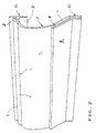
- This section of profile successively comprises (FIG. 6) from top to bottom: an upper groove 4, in which the upper edge H of said window is embedded and whose external flank is formed by the upper part 2 of a front band B1 whose base 3 constitutes the gripping member of the handle 1, while the internal flank of this groove 4 is constituted by the shoulder 5 of an inclined ramp R connected to the shoulder 5 by a longitudinal flat top S , and delimiting with said shoulder a prismatic volume 6 inside the handle 1; this ramp R itself; a concave, substantially vertical part V , connected to the ramp R by an inflection edge L (see also FIGS. 2 and 4), forming a housing for the fingers of the user's hand and conforming to their contour (FIG.
- a substantially planar and inclined part P respectively P ' (FIG. 6A); and, finally, a second front strip B2 , parallel to the first, B1 , and carrying, inwards, under the inclined flat part P , or P ' (FIG. 6 A ), a second groove 7, lower, in which comes fit the lower edge B of the window.
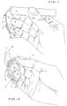
- the substantially vertical concave part V of the handle 1 is conformed to the contour of the fingers of the hand of the user which come to lodge there naturally (ergonomic characteristic of the handle), limiting to the strict minimum (approximately 1.5 cm / Figures 5 and 5 A ) the depth of the handle, which therefore encroaches very little on the interior volume of the drawer: while the thumb, ⁇ , is supported on the first front band B1 ( Figure 7), the last two phalanges of the index, ⁇ , are housed in contact with the prismatic volume 6 and the upper part of the concave part V , in front support on the base 3 of this strip B1 , base 3 which , pinched between this index, ⁇ , and the thumb, ⁇ , constitutes the gripping member of said handle.
- the last phalanges of the four joined fingers can also be accommodated in the handle, oriented from bottom to top, in simultaneous engagement of their four ends aligned in the prismatic volume 6.
- This handle 1 being designed to removably carry a label identifying the content of the drawer equipped with this handle, said substantially flat part, P , of the section of section of which it is formed, consists of a strip of transparent material, U , in this case a transparent "crystal” polyvinyl chloride (PVC) strip, integral with the rest of the profile and coming in one piece with it by bi-injection extrusion.
- U transparent material
- PVC polyvinyl chloride
- the underside of the strip of transparent material U, inside said housing 8, can be, in accordance with the drawing and advantageously, slightly curved, so as to apply, under slight pressure, the label E (figure 9) or E '(figure 10) against said flat longitudinal base 9 and to prevent its inadvertent sliding, in particular by inertia.
- planar can only be provided at the right width of the housing or, as a variant shown in FIG. 10, this label E ′ can be provided to occupy the entire width of the housing 8 and present then, like said housing 8, an elbow X.
- the upper surface of said strip of transparent material is slightly curved, forming a cylindrical magnifying glass G , to enlarge the vision of the inscriptions carried by the label E or E '(handle 1 a ).
- this transparent material can be tinted in its mass, regardless of the color of the label E or E ', in order to increase the variety of the handle.
- the drawer also an object of the invention as it is intended to be equipped with the handle described above and to be adapted to it, present, according to its preferred embodiment, a front face T , T 'or T ''in sheet metal, pierced with a window, rectangular in shape, the width of the handle ( Figure 12).
- this window consists of a simple rectangular opening, with lower edges B , upper H and lateral edges C and C ', two to two parallel opposites, cut into sharp edges , with a cookie cutter, in the front face T of the drawer ( Figure 13).
- Figures 14 and 19 show on the one hand that it is then possible to insert the label E in its housing 8 through the interior of the drawer, on the other hand that the interior of the drawer then remains in communication with the outside, by the open side flanks of the handle 1.
- the two lower edges B and upper H remaining cut into sharp edges, the two lateral edges of said window consist of two parallel cheeks J and J ', obtained by folding at 90 °, towards the inside of the drawer, of two symmetrical cutouts made in its front face T ', with the complete contour of the profile, taken between the levels of the upper H and lower B edges of the window, this folding being effected according to the two fold lines 12 and 12 ′ at the spacing of the width of the handle, and these two cheeks J and J ′ closing laterally the entire profile comprised between these two levels, including the housing 8 in which, consequently, must be inserted the label E or E 'before embedding the handle 1 in this window.
- the two lower edges B and upper H remaining cut into sharp edges, the two lateral edges of said window are formed by two parallel cheeks K and K ', obtained by folding at 90 °, towards the inside of the drawer, and along the two fold lines 13 and 13 'at the distance of the width of the handle, from two symmetrical cutouts made in its front face T '', at the contour of the profile taken between the levels of the upper H and lower B edges of the window, with the exception of the lateral openings of said housing 8 into which, therefore, the label E can be inserted, from inside the drawer, after embedding the handle 1 in this window.
- the handle can, if necessary, be extracted therefrom, but so voluntary, from inside the drawer, by bending the profile, releasing the upper edge H of the window from the upper groove 4, and pushed out of the window, which excludes any untimely extraction, in particular the closed drawer.
- the handle according to the invention can naturally any as well to equip all kinds of walls, especially metallic, in order to allow its operation.
- the wall according to the invention can constitute such a front of a drawer, operated by the handle, according to the direction perpendicular to the wall.
- This wall can also constitute the front face of a hinged door, in particular the door of a wardrobe, or that of a workshop cupboard.
- the handle can then be mounted horizontally, as shown in Figure 3, or, better, vertically as it appears on plate VII / 12 (figure 12) of drawing. Fitting the door with a locker, the handle label holder according to the invention allows the identification of its user, by name or by entering a number.
- This wall can also constitute the front face of a sliding door or partition, or the amount of a sliding curtain, the body of the handle coming to be housed between this face front and the opposite side of the sliding door or partition, respectively in the amount of the sliding curtain.
- Said wall can also constitute one of the two sides side of a piece of furniture, portable thanks to two copies of the handle according to the invention, arranged horizontally as shown in Figure 3, each of these two copies, opposite on the other, being carried by one of these two lateral flanks.
Landscapes
- Details Of Rigid Or Semi-Rigid Containers (AREA)
- Drawers Of Furniture (AREA)
- Vehicle Step Arrangements And Article Storage (AREA)
Description
- d'une portion basse, de structure complexe, dont la face avant, en pan incliné, se termine par une bande frontale inférieure venant s'appliquer contre la bordure externe du bord inférieur de la fenêtre, et dont la configuration triangulaire massive, donc encombrante, est rendue nécessaire par la disposition, dans sa masse, sur toute la longueur du tronçon : d'un canal cruciforme - dans les extrémités duquel s'encastrent les tenons inférieurs (figure 3 et 4 dudit document) des flancs latéraux (page 10, lignes 23 à 25 dudit document) - , de ladite encoche inférieure hémi-cylindrique, et d'une gorge, de section oblongue, à ouverture inférieure, dans les extrémités de laquelle s'encastrent les tenons extrêmes, de même section oblongue, (figures 3 et 4 dudit document) des flancs latéraux ;
- d'une portion intermédiaire verticale, strictement plane et prolongeant vers le haut ladite face frontale, en pan incliné, de la portion basse précédente, et formant avec elle un dièdre inconfortable pour les doigts de l'utilisateur de la poignée ; et
- d'une portion haute, également de structure complexe, prolongeant vers le haut la portion intermédiaire, et qui porte une bande frontale supérieure dont la partie supérieure vient s'appliquer contre la bordure externe du bord supérieur de la fenêtre et y est retenue par deux vis, à travers deux orifices, à épanouissements tronconiques, dont est percée cette partie supérieure, symétriquement l'un de l'autre par rapport au plan de section, médian, du corps (page 9, § 3 dudit document), orifices qui rendent non strictement uniforme la section droite du tronçon de profilé utilisé, qui doit donc être façonné après découpe; la base de cette bande frontale supérieure constituant l'organe de préhension de la poignée ; cette portion haute, horizontale, présentant une configuration rectangulaire massive, donc encombrante, rendue nécessaire par la disposition, dans sa masse, sur toute la longueur du tronçon : d'un canal cruciforme - dans les extrémités duquel s'encastrent les tenons supérieurs (figures 3 et 4 dudit document) des flancs latéraux (page 11, § 3 dudit document) - et d'une profonde gorge, obligeant à surépaissir ledit organe de préhension de la poignée ;
- la figure 1 représente, vue de face en perspective cavalière, une poignée selon la forme préférée de réalisation de l'invention,
- la figure 2 représente, vue de dos en perspective cavalière, la poignée représentée à la figure 1,
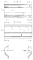
- les figures 3 et 4 montrent cette même poignée, respectivement de face et de dos, aux dimensions-mêmes de la poignée (échelle 1 : 1),
- les figures 5 et 5A représentent cette même poignée en bout, respectivement selon les lignes V-V et VA-VA des figures 3 et 4,
- la figure 6 est un agrandissement notable de la figure 5, permettant de mieux faire ressortir tous les éléments de cette poignée,
- la figure 6A représente, en bout et à une échelle plus réduite, une variante "aveugle" de la poignée, sans port d'étiquette,
- les figures 7 et 8 représentent, respectivement de face en perspective cavalière et en bout, la poignée, dépourvue de son étiquette, déjà représentée aux figures 1 à 6, en position de préhension par la main de l'utilisateur,
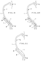
- les figures 9 et 10 montrent en bout cette même poignée équipée de son étiquette, respectivement d'une variante de celle-ci,
- la figure 11 représente, en bout, une variante de cette poignée, équipée d'une loupe cylindrique permettant d'agrandir la vision des inscriptions portées par l'étiquette, non représentée,
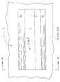
- la figure 12 montre partiellement la face frontale d'un tiroir équipé d'une poignée selon l'invention,
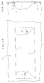
- la figure 13 représente, poignée enlevée, cette même face frontale du tiroir, selon la forme préférée de réalisation de celui-ci, à fenêtre réduite à une ouverture rectangulaire,
- la figure 14 est une coupe de cette face frontale équipée de la poignée, selon la ligne A-A de la figure 12,
- la figure 15 représente, poignée enlevée, la face frontale du tiroir, selon une première variante de réalisation, "à joues latérales" de sa fenêtre,
- la figure 16 est une coupe de cette dernière face frontale équipée de la poignée, selon la ligne A-A de la figure 12,
- la figure 17 représente, poignée enlevée, la face frontale du tiroir, selon une seconde variante de réalisation, "à joues latérales" de sa fenêtre,
- la figure 18 est une coupe de cette dernière face-frontale équipée de la poignée, selon la ligne A-A de la figure 12,
- les figures 19, 20 et 21 représentent, vues agrandies, en perspective arrière partielle les formes de réalisation déjà montrées en coupes, respectivement aux figures 14, 16 et 18.
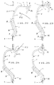
- les figures 22 à 25 montrent, en coupe, les quatre phases successives de l'encastrement de la poignée dans la fenêtre de la face frontale du tiroir, par clipsage entre les deux bords inférieur et supérieur de cette fenêtre, seuls éléments de cette fenêtre à y être représentés, la poignée y apparaissant dépourvue d'étiquette.
Claims (8)
- Poignée pour paroi, notamment la paroi frontale d'un tiroir, sur laquelle on la monte, retenue par les bords parallèles supérieur (H) et inférieur (B) d'une fenêtre rectangulaire percée dans la paroi, poignée comprenant un troncon de profilé dépourvu de flancs lateraux d'extrémités, dont la section droite présente sensiblement la forme d'un point d'interrogation et qui est pourvue d'une bande frontale supérieure (B1), dont la partie supérieure (2) recouvre frontalement ledit bord supérieur et dont la base (3) constitue l'organe de préhension de la poignée, ainsi que d'une partie basse inclinée sensiblement plane (P,P') portant une bande frontale inférieure (B2) recouvrant frontalement ledit bord inférieur (B); caractérisée en ce que le tronçon de profilé est dépourvu de flancs lateraux d'extrémités et en ce que d'une part, elle est seulement constituée, à l'exclusion de tout autre élément constitutif, par ledit et unique tronçon de profilé, de section droite strictement uniforme sur toute sa longueur, sensiblement au profil, mince, dudit point d'interrogation, d'un seul tenant en une matière seulement flexible, notamment du chlorure de polyvinyle ; et, d'autre part, comprend, constituant les éléments successifs de ce tronçon de profilé, de bas en haut de son profil : une rainure inférieure (7) d'encastrement dudit bord inférieur (B) entre ses deux flancs avant, formé par ladite bande frontale inférieure (B2), et arrière, ladite partie basse inclinée sensiblement plane (P,P') et, en continuité et dans le prolongement de celle-ci, une partie médiane concave sensiblement verticale (V), conformée ergonomiquement au contour des doigts de la main de l'utilisateur, puis, raccordée à celle-ci par une arête d'inflexion (L), une rampe inclinée (R), sur laquelle, par introduction de la poignée dans la fenêtre, vient s'appuyer, provoquant la flexion du tronçon de profilé, le bord supérieur (H) de la fenêtre, enfin, un épaulement frontal (5) de cette rampe inclinée (R),formant saillant avec elle et délimitant avec elle un volume prismatique (6) augmentant le volume intérieur de la poignée, ledit épaulement (5) constituant le flanc interne d'une rainure supérieure (4) d'encastrement dudit bord supérieur (H), dont l'autre flanc, avant, est formé par la partie supérieure (2) de ladite bande frontale supérieure (B1), ledit bord supérieur (H) venant s'encastrer, en retenue de la poignée dans la fenêtre par simple clipsage, dans cette rainure supérieure (4), dès que cette dernière vient à l'aplomb dudit bord supérieur (H).
- Poignée pour paroi selon la revendication 1, caractérisée en ce que, cette poignée (1) étant conçue pour porter amoviblement une étiquette (E,E') d'identification du contenu d'un tiroir, ladite partie sensiblement plane (P) du tronçon de profilé est constituée d'une bande de matière transparente (U), notamment une bande de chlorure de polyvinyle transparent solidaire du reste du profilé et venue d'une pièce avec celui-ci par extrusion en bi-injection, et que, parallèlement à et sous cette partie sensiblement plane (P) du tronçon de profilé, délimitant avec cette bande transparente (U) un logement longitudinal mince (8) dans lequel on insère l'étiquette (E,E'), est prévue dans le profilé une paroi longitudinale plane (9), dont la base, coudée (11), vient prolonger vers le haut le flanc arrière de ladite rainure inférieure (7) et dont l'extrémité supérieure (10) vient se raccorder au reste du profilé au niveau de la jonction de sa partie concave, sensiblement vertiticale (V), et de sa partie sensiblement plane, oblique (P).
- Poignée selon la revendication 2, caractérisée en ce que la face inférieure de la bande de matière transparente (U), intérieure audit logement (8), est légèrement bombée, de manière à appliquer, en légère pression, l'étiquette (E,E') contre ladite base longitudinale plane (9) et à prévenir son glissement intempestif, notamment par inertie.
- Poignée selon la revendication 2, caractérisée en ce que la face supérieure de la bande de matière transparente est légèrement bombée, formant loupe cylindrique (G), pour agrandir la vision des inscriptions portées par l'étiquette (E,E').
- Poignée selon la revendication 2, caractérisée en ce que ladite matière transparente est teintée dans sa masse, indépendamment de la couleur de l'étiquette (E,E'), afin d'augmenter la variété de ladite poignée.
- Poignée selon la des revendication 2, caractérisée en ce que l'étiquette (E'), étant prévue pour occuper toute la largeur dudit logement (8), elle présente, à l'instar de ce logement (8), un coude (X).
- Paroi percée d'une fenêtre rectangulaire, destinée à être équipée d'une poignée selon la revendication 1, caractérisée en ce que les deux bords latéraux de ladite fenêtre sont constitués par deux joues parallèles (J,J'), obtenues par rabattement à 90° de deux découpes symétriques pratiquées dans la surface (T') de la paroi, au contour complet du profilé, pris entre les niveaux des bords supérieur (H) et inférieur (B) de la fenêtre, ces deux joues obturant latéralement la totalité du profilé compris entre ces deux niveaux.
- Paroi percée d'une fenêtre rectangulaire, destinée à être équipée d'une poignée selon la revendication 2, caractérisée en ce que les deux bords latéraux de ladite fenêtre sont constitués par deux joues parallèles (K,K'), obtenues par rabattement à 90° de deux découpes symétriques pratiquées dans la surface (T'') de la paroi au contour du profilé pris entre les niveaux des bords supérieur (H) et inférieur (B) de la fenêtre, à l'exception des ouvertures latérales dudit logement (8) dans lequel, dès lors, peut être insérée l'étiquette (E), par derrière ladite paroi après encastrement de la poignée dans la fenêtre de celle-ci.
Applications Claiming Priority (2)
| Application Number | Priority Date | Filing Date | Title |
|---|---|---|---|
| FR9403354 | 1994-03-22 | ||
| FR9403354A FR2717664B1 (fr) | 1994-03-22 | 1994-03-22 | Poignée, notamment porte-étiquette, pour paroi et paroi, notamment paroi frontale de tiroir, destinée à en être équipée. |
Publications (2)
| Publication Number | Publication Date |
|---|---|
| EP0678258A1 EP0678258A1 (fr) | 1995-10-25 |
| EP0678258B1 true EP0678258B1 (fr) | 1999-01-27 |
Family
ID=9461305
Family Applications (1)
| Application Number | Title | Priority Date | Filing Date |
|---|---|---|---|
| EP95400616A Expired - Lifetime EP0678258B1 (fr) | 1994-03-22 | 1995-03-21 | Poignée, notamment porte-étiquette, pour paroi et paroi, notamment paroi frontale de tiroir, destinée à en être équipée |
Country Status (5)
| Country | Link |
|---|---|
| EP (1) | EP0678258B1 (fr) |
| AT (1) | ATE176136T1 (fr) |
| DE (1) | DE69507529T2 (fr) |
| ES (1) | ES2129769T3 (fr) |
| FR (1) | FR2717664B1 (fr) |
Cited By (3)
| Publication number | Priority date | Publication date | Assignee | Title |
|---|---|---|---|---|
| US10893749B1 (en) | 2019-09-26 | 2021-01-19 | Liberty Hardware Mfg. Corp. | Hardware handle assembly |
| US11445825B2 (en) | 2019-09-26 | 2022-09-20 | Liberty Hardware Mfg. Corp. | Hardware bar assembly |
| US12144468B2 (en) | 2019-11-08 | 2024-11-19 | Liberty Hardware Mfg. Corp. | Wall mount bar assembly |
Families Citing this family (4)
| Publication number | Priority date | Publication date | Assignee | Title |
|---|---|---|---|---|
| CH703948B1 (de) * | 2003-02-19 | 2012-04-30 | Lista Europ Holding Ag | Griffleiste für eine Schublade, insbesondere für eine Schublade von Lager- und Betriebsmitteleinrichtungen. |
| US7007347B2 (en) * | 2003-12-18 | 2006-03-07 | Haworth, Inc. | Drawer pull |
| CN102294686A (zh) * | 2010-06-23 | 2011-12-28 | 平湖市陈达仓储办公设备有限公司 | 工具柜抽屉把手 |
| WO2017059907A1 (fr) * | 2015-10-08 | 2017-04-13 | Arcelik Anonim Sirketi | Ensemble tiroir pour machine à laver |
Family Cites Families (2)
| Publication number | Priority date | Publication date | Assignee | Title |
|---|---|---|---|---|
| DE8806453U1 (de) * | 1988-05-17 | 1988-10-20 | Rohde & Sohn GmbH + Co KG, 3412 Nörten-Hardenberg | In eine Öffnung einer Gehäusewand einsetzbarer Schalengriff |
| GB2234165B (en) * | 1989-07-27 | 1992-07-01 | Southco | One piece pull having snap-in action |
-
1994
- 1994-03-22 FR FR9403354A patent/FR2717664B1/fr not_active Expired - Lifetime
-
1995
- 1995-03-21 DE DE69507529T patent/DE69507529T2/de not_active Expired - Fee Related
- 1995-03-21 ES ES95400616T patent/ES2129769T3/es not_active Expired - Lifetime
- 1995-03-21 AT AT95400616T patent/ATE176136T1/de not_active IP Right Cessation
- 1995-03-21 EP EP95400616A patent/EP0678258B1/fr not_active Expired - Lifetime
Cited By (4)
| Publication number | Priority date | Publication date | Assignee | Title |
|---|---|---|---|---|
| US10893749B1 (en) | 2019-09-26 | 2021-01-19 | Liberty Hardware Mfg. Corp. | Hardware handle assembly |
| US11445825B2 (en) | 2019-09-26 | 2022-09-20 | Liberty Hardware Mfg. Corp. | Hardware bar assembly |
| US12114773B2 (en) | 2019-09-26 | 2024-10-15 | Liberty Hardware Mfg. Corp. | Hardware bar assembly |
| US12144468B2 (en) | 2019-11-08 | 2024-11-19 | Liberty Hardware Mfg. Corp. | Wall mount bar assembly |
Also Published As
| Publication number | Publication date |
|---|---|
| FR2717664A1 (fr) | 1995-09-29 |
| EP0678258A1 (fr) | 1995-10-25 |
| ES2129769T3 (es) | 1999-06-16 |
| DE69507529D1 (de) | 1999-03-11 |
| DE69507529T2 (de) | 1999-09-16 |
| FR2717664B1 (fr) | 1996-06-21 |
| ATE176136T1 (de) | 1999-02-15 |
Similar Documents
| Publication | Publication Date | Title |
|---|---|---|
| BE1000021A6 (fr) | Tete de cle et cle pourvue d'une telle tete. | |
| CA2223863C (fr) | Distribution de gants constitues dans un materiau en feuille | |
| FR2620313A1 (fr) | Boite a fard | |
| EP0279753B1 (fr) | Chevalet de conférence | |
| FR2853280A1 (fr) | Classeur a etiquette de dos et construction de classeur | |
| EP0678258A1 (fr) | Poignée, notamment porte-étiquette, pour paroi et paroi, notamment paroi frontale de tiroir, destinée à en être équipée | |
| EP1500347A1 (fr) | Boítier cosmétique à tiroir éjectable | |
| FR2534123A1 (fr) | Poignee en longueur remplissant une fonction d'organisation et tiroir ou porte en comportant l'utilisation | |
| LU81959A1 (fr) | Rail de serrage avec chambre destinee a recevoir des documents d'organisation | |
| FR2652374A1 (fr) | Poignee pour portiere de vehicule a moteur. | |
| FR2756651A1 (fr) | Porte-affiche du type a encadrement avec plaque souple transparente pour le maintien de l'affiche | |
| EP1132237B1 (fr) | Ouvrant de véhicule, notamment hayon | |
| FR2499839A1 (fr) | Perfectionnements aux cadres pour gravures, photographies ou analogues | |
| EP0246449A1 (fr) | Ensemble comprenant un élément de boîte de montre et un bracelet | |
| EP1857856A1 (fr) | Lunettes à montures amovibles | |
| FR2681402A1 (fr) | Profiles d'ossature, notamment pour armoire pour appareillages electriques, et accessoires susceptibles d'etre associes a un tel profile d'ossature. | |
| FR2877985A1 (fr) | Joue pour coffre de volet et coffre comprenant au moins deux joues | |
| CH595078A5 (en) | Presentation display box for perfume or jewellery | |
| FR2783555A1 (fr) | Joint anti-pince-doigt pour porte va-et-vient ou porte va-et-vient coupe-feu | |
| FR2625889A1 (fr) | Cadre pour un objet plan | |
| EP1029707B1 (fr) | Boíte de classement | |
| EP4455429A1 (fr) | Panneau brise-vue ou d'occultation de clôtures en treillis rigide et son procédé de fixation | |
| FR2663495A1 (fr) | Porte degondable pour coffret et coffret correspondant. | |
| FR2591444A1 (fr) | Parapluie ou parasol jetable | |
| FR2803999A1 (fr) | Cadre de plastification |
Legal Events
| Date | Code | Title | Description |
|---|---|---|---|
| PUAI | Public reference made under article 153(3) epc to a published international application that has entered the european phase |
Free format text: ORIGINAL CODE: 0009012 |
|
| 17P | Request for examination filed |
Effective date: 19950328 |
|
| AK | Designated contracting states |
Kind code of ref document: A1 Designated state(s): AT BE CH DE DK ES GB GR IE IT LI LU MC NL PT SE |
|
| 17Q | First examination report despatched |
Effective date: 19970612 |
|
| GRAG | Despatch of communication of intention to grant |
Free format text: ORIGINAL CODE: EPIDOS AGRA |
|
| GRAG | Despatch of communication of intention to grant |
Free format text: ORIGINAL CODE: EPIDOS AGRA |
|
| GRAG | Despatch of communication of intention to grant |
Free format text: ORIGINAL CODE: EPIDOS AGRA |
|
| GRAH | Despatch of communication of intention to grant a patent |
Free format text: ORIGINAL CODE: EPIDOS IGRA |
|
| GRAH | Despatch of communication of intention to grant a patent |
Free format text: ORIGINAL CODE: EPIDOS IGRA |
|
| GRAA | (expected) grant |
Free format text: ORIGINAL CODE: 0009210 |
|
| AK | Designated contracting states |
Kind code of ref document: B1 Designated state(s): AT BE CH DE DK ES GB GR IE IT LI LU MC NL PT SE |
|
| PG25 | Lapsed in a contracting state [announced via postgrant information from national office to epo] |
Ref country code: SE Free format text: THE PATENT HAS BEEN ANNULLED BY A DECISION OF A NATIONAL AUTHORITY Effective date: 19990127 Ref country code: NL Free format text: LAPSE BECAUSE OF FAILURE TO SUBMIT A TRANSLATION OF THE DESCRIPTION OR TO PAY THE FEE WITHIN THE PRESCRIBED TIME-LIMIT Effective date: 19990127 Ref country code: IT Free format text: LAPSE BECAUSE OF FAILURE TO SUBMIT A TRANSLATION OF THE DESCRIPTION OR TO PAY THE FEE WITHIN THE PRESCRIBED TIME-LIMIT;WARNING: LAPSES OF ITALIAN PATENTS WITH EFFECTIVE DATE BEFORE 2007 MAY HAVE OCCURRED AT ANY TIME BEFORE 2007. THE CORRECT EFFECTIVE DATE MAY BE DIFFERENT FROM THE ONE RECORDED. Effective date: 19990127 Ref country code: GR Free format text: LAPSE BECAUSE OF NON-PAYMENT OF DUE FEES Effective date: 19990127 Ref country code: AT Free format text: LAPSE BECAUSE OF FAILURE TO SUBMIT A TRANSLATION OF THE DESCRIPTION OR TO PAY THE FEE WITHIN THE PRESCRIBED TIME-LIMIT Effective date: 19990127 |
|
| REF | Corresponds to: |
Ref document number: 176136 Country of ref document: AT Date of ref document: 19990215 Kind code of ref document: T |
|
| REG | Reference to a national code |
Ref country code: CH Ref legal event code: EP |
|
| REG | Reference to a national code |
Ref country code: IE Ref legal event code: FG4D Free format text: FRENCH |
|
| REF | Corresponds to: |
Ref document number: 69507529 Country of ref document: DE Date of ref document: 19990311 |
|
| PG25 | Lapsed in a contracting state [announced via postgrant information from national office to epo] |
Ref country code: LI Free format text: LAPSE BECAUSE OF NON-PAYMENT OF DUE FEES Effective date: 19990331 Ref country code: CH Free format text: LAPSE BECAUSE OF NON-PAYMENT OF DUE FEES Effective date: 19990331 |
|
| PG25 | Lapsed in a contracting state [announced via postgrant information from national office to epo] |
Ref country code: MC Free format text: THE PATENT HAS BEEN ANNULLED BY A DECISION OF A NATIONAL AUTHORITY Effective date: 19990420 |
|
| PG25 | Lapsed in a contracting state [announced via postgrant information from national office to epo] |
Ref country code: PT Free format text: LAPSE BECAUSE OF FAILURE TO SUBMIT A TRANSLATION OF THE DESCRIPTION OR TO PAY THE FEE WITHIN THE PRESCRIBED TIME-LIMIT Effective date: 19990427 Ref country code: DK Free format text: LAPSE BECAUSE OF FAILURE TO SUBMIT A TRANSLATION OF THE DESCRIPTION OR TO PAY THE FEE WITHIN THE PRESCRIBED TIME-LIMIT Effective date: 19990427 |
|
| GBT | Gb: translation of ep patent filed (gb section 77(6)(a)/1977) |
Effective date: 19990409 |
|
| REG | Reference to a national code |
Ref country code: ES Ref legal event code: FG2A Ref document number: 2129769 Country of ref document: ES Kind code of ref document: T3 |
|
| NLV1 | Nl: lapsed or annulled due to failure to fulfill the requirements of art. 29p and 29m of the patents act | ||
| PG25 | Lapsed in a contracting state [announced via postgrant information from national office to epo] |
Ref country code: IE Free format text: LAPSE BECAUSE OF NON-PAYMENT OF DUE FEES Effective date: 19990820 |
|
| REG | Reference to a national code |
Ref country code: IE Ref legal event code: FD4D |
|
| REG | Reference to a national code |
Ref country code: CH Ref legal event code: PL |
|
| PLBE | No opposition filed within time limit |
Free format text: ORIGINAL CODE: 0009261 |
|
| STAA | Information on the status of an ep patent application or granted ep patent |
Free format text: STATUS: NO OPPOSITION FILED WITHIN TIME LIMIT |
|
| 26N | No opposition filed | ||
| REG | Reference to a national code |
Ref country code: GB Ref legal event code: IF02 |
|
| PGFP | Annual fee paid to national office [announced via postgrant information from national office to epo] |
Ref country code: LU Payment date: 20050314 Year of fee payment: 11 |
|
| PGFP | Annual fee paid to national office [announced via postgrant information from national office to epo] |
Ref country code: GB Payment date: 20050415 Year of fee payment: 11 |
|
| PGFP | Annual fee paid to national office [announced via postgrant information from national office to epo] |
Ref country code: BE Payment date: 20050419 Year of fee payment: 11 |
|
| PGFP | Annual fee paid to national office [announced via postgrant information from national office to epo] |
Ref country code: ES Payment date: 20050425 Year of fee payment: 11 |
|
| PGFP | Annual fee paid to national office [announced via postgrant information from national office to epo] |
Ref country code: DE Payment date: 20050513 Year of fee payment: 11 |
|
| PG25 | Lapsed in a contracting state [announced via postgrant information from national office to epo] |
Ref country code: GB Free format text: LAPSE BECAUSE OF NON-PAYMENT OF DUE FEES Effective date: 20060321 |
|
| PG25 | Lapsed in a contracting state [announced via postgrant information from national office to epo] |
Ref country code: ES Free format text: LAPSE BECAUSE OF NON-PAYMENT OF DUE FEES Effective date: 20060322 |
|
| PG25 | Lapsed in a contracting state [announced via postgrant information from national office to epo] |
Ref country code: LU Free format text: LAPSE BECAUSE OF NON-PAYMENT OF DUE FEES Effective date: 20060331 Ref country code: BE Free format text: LAPSE BECAUSE OF NON-PAYMENT OF DUE FEES Effective date: 20060331 |
|
| PG25 | Lapsed in a contracting state [announced via postgrant information from national office to epo] |
Ref country code: DE Free format text: LAPSE BECAUSE OF NON-PAYMENT OF DUE FEES Effective date: 20061003 |
|
| GBPC | Gb: european patent ceased through non-payment of renewal fee |
Effective date: 20060321 |
|
| REG | Reference to a national code |
Ref country code: ES Ref legal event code: FD2A Effective date: 20060322 |
|
| BERE | Be: lapsed |
Owner name: SOC. DES BAGAGES HENRY *PIERRE Effective date: 20060331 |