EP0678271A2 - Circuit pour régler la puissance d'aspiration d'un aspirateur de poussière - Google Patents
Circuit pour régler la puissance d'aspiration d'un aspirateur de poussière Download PDFInfo
- Publication number
- EP0678271A2 EP0678271A2 EP95105303A EP95105303A EP0678271A2 EP 0678271 A2 EP0678271 A2 EP 0678271A2 EP 95105303 A EP95105303 A EP 95105303A EP 95105303 A EP95105303 A EP 95105303A EP 0678271 A2 EP0678271 A2 EP 0678271A2
- Authority
- EP
- European Patent Office
- Prior art keywords
- control
- control signal
- circuit arrangement
- circuit
- arrangement according
- Prior art date
- Legal status (The legal status is an assumption and is not a legal conclusion. Google has not performed a legal analysis and makes no representation as to the accuracy of the status listed.)
- Granted
Links
Images

Classifications
-
- A—HUMAN NECESSITIES
- A47—FURNITURE; DOMESTIC ARTICLES OR APPLIANCES; COFFEE MILLS; SPICE MILLS; SUCTION CLEANERS IN GENERAL
- A47L—DOMESTIC WASHING OR CLEANING; SUCTION CLEANERS IN GENERAL
- A47L9/00—Details or accessories of suction cleaners, e.g. mechanical means for controlling the suction or for effecting pulsating action; Storing devices specially adapted to suction cleaners or parts thereof; Carrying-vehicles specially adapted for suction cleaners
- A47L9/28—Installation of the electric equipment, e.g. adaptation or attachment to the suction cleaner; Controlling suction cleaners by electric means
- A47L9/2857—User input or output elements for control, e.g. buttons, switches or displays
-
- A—HUMAN NECESSITIES
- A47—FURNITURE; DOMESTIC ARTICLES OR APPLIANCES; COFFEE MILLS; SPICE MILLS; SUCTION CLEANERS IN GENERAL
- A47L—DOMESTIC WASHING OR CLEANING; SUCTION CLEANERS IN GENERAL
- A47L9/00—Details or accessories of suction cleaners, e.g. mechanical means for controlling the suction or for effecting pulsating action; Storing devices specially adapted to suction cleaners or parts thereof; Carrying-vehicles specially adapted for suction cleaners
- A47L9/28—Installation of the electric equipment, e.g. adaptation or attachment to the suction cleaner; Controlling suction cleaners by electric means
- A47L9/2836—Installation of the electric equipment, e.g. adaptation or attachment to the suction cleaner; Controlling suction cleaners by electric means characterised by the parts which are controlled
- A47L9/2842—Suction motors or blowers
Definitions
- the invention relates to a circuit arrangement for controlling the suction power of a vacuum cleaner
- a device for automatic suction control of a vacuum cleaner is known.
- two pressure switches responding to different pressures are provided, the switching pulses of which trigger corresponding functions in a connected control circuit. Because of the two pressure switches there is a "directional dependence" of the device, i.e. In order to ensure proper functioning of the device, the pressure switch which responds to a lower pressure and which responds to a higher pressure must be connected to a particular point in the control circuit. If these connection options are mixed up when the device is installed, the device will not function. The use of two pressure switches also means an increased material expenditure.
- the invention is based on the object of designing a circuit arrangement for controlling the suction power of a vacuum cleaner in such a way that only one pressure switch is required and thus simpler assembly is achieved and furthermore an inoperability of the circuit arrangement is avoided by incorrect assembly.
- the control pulses formed in accordance with the comparison of the periodically variable signal with the control signal for the semiconductor switching element can by a change in the control signal can be controlled accordingly.
- the control signal can be changed manually by adjusting a potentiometer, whereby a constant power of the blower motor corresponding to the potentiometer position is specified.
- the opening and closing of the pressure switch which corresponds to the respective pressure conditions, switches back and forth between two voltage values specified for the control signal, so that, in the manner of a two-point control, the blower motor's output is controlled in such a way that a constant or at least approximately constant negative pressure is generated .
- the comparator consists of an operational amplifier, at whose one input there is a sawtooth voltage synchronized with the mains voltage of the blower motor and at whose other input the control signal is supplied.
- Low-noise ignition pulses for the controllable semiconductor switching elements can be generated in that the output of the operational amplifier is connected via a differentiating element to the one input of a comparator, at the other input of which there is a fixed comparison voltage.
- the control signal can be changed on the one hand by a manually operated potentiometer or on the other hand by means of a pressure switch connected in parallel with a resistor. In the latter case, there is an automatic regulation of the negative pressure. Because of the respective negative pressure Depending on the opening or closing of the pressure switch, the parallel resistor is either switched on or off, so that the control signal oscillates between two voltage values. Accordingly, the power of the blower motor is increased or decreased, so that a constant or at least approximately constant negative pressure is established on average.
- a switch can advantageously be provided, with which it is possible to switch between manual setting by means of a potentiometer and automatic vacuum control.
- the power control of the blower motor is expediently limited to a minimum and a maximum value by additional resistances in the control signal circuit.
- a smooth start of the blower motor after switching on is easily achieved in that an additional signal is fed into the supply connection of the control signal to the comparator by means of a series RC element.
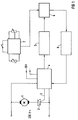
- the semiconductor switching element 2 is connected with its control connection 3 to a power section 4.
- a synchronous part 5, which acts on a control part 6, is connected to the power part 4.
- a control part 7 also acts on this control part 6.
- the control part 6 in turn influences an ignition pulse part 8 which, with its output, controls the element of the power part 4 controlling the semiconductor switching element 2 accordingly.
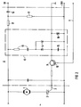
- This element controlling the semiconductor switching element 2 is, as can be seen from FIG. 2, a control transistor 9, the base 10 of which is connected to the ignition pulse part 8 via a first control line 11.
- the power section 4 also contains a circuit section 12 for generating a DC supply voltage.
- the circuit part 12 has a series RC element 13, to which two diodes 14 are antiparallel in series.
- the other connection side of the two diodes 14 is in each case connected to one pole of a smoothing capacitor 15.
- a zener diode 16 for voltage stabilization is also connected in parallel with the smoothing capacitor 15.
- the voltage present at the smoothing capacitor 15 represents the DC supply voltage for the circuit arrangement.
- the power section 4 also contains a first voltage divider 17 which is connected to the supply voltage of the blower motor 1 and to the tap of which a filter capacitor 18 is connected with its one connection pole.
- This filter capacitor 18 may result in the divided AC voltage contained DC voltage components suppressed.
- the synchronizing part 5 is connected to the other connection pole 19 of the filter capacitor 18.
- the synchronous part 5 has a window comparator consisting of first and second operational amplifiers 20 and 21.
- the AC voltage supplied by the filter capacitor 18 is applied to the inverting input of the first operational amplifier 20 and to the non-inverting input of the second operational amplifier 21.
- the two operational amplifiers 20 and 21 are connected to the DC supply voltage via divider resistors 22.
- a window comparator connected in this way, narrow square-wave pulses are produced at the output 23 at each zero crossing of the AC voltage.
- a charging transistor 26 connected in parallel with its collector-emitter path to a capacitor 25 connected via a series resistor 24 to the DC supply voltage is driven by these pulses.
- the capacitor 25 is periodically discharged via a discharge resistor 27 located in the collector-emitter circuit via the discharge transistor 26 which is controlled during the duration of the rectangular pulses. During the blocking period of the discharge transistor 26, the capacitor 25 is charged again in each case. A sawtooth-shaped voltage is thus formed. This sawtooth-shaped voltage is applied to the inverting input of an operational amplifier 28 acting as a comparator. A control signal is fed to the non-inverting input of this operational amplifier 28 via a second control line 29.
- a differentiator 31 is connected to the output 30 of the operational amplifier 28, which acts as a comparator, the output 32 of which is connected to the inverting input of a comparator 33 and the non-inverting input of which is connected by means of a second voltage divider 34 Reference voltage is set.
- the output 35 of the comparator 33 is connected to the base 10 of the control transistor 9 via the first control line 11.
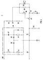
- the control section 7 contains a third voltage divider 36, to the tap 37 of which a potentiometer 38 and the parallel connection of a control resistor 39 with a pressure switch 40 are connected.
- the parallel connection consisting of the control resistor 39 and the pressure switch 40 is also connected to ground via a control RC element 41.
- Via a changeover switch 42 the tap of the potentiometer 38 or the common connection point 43 of the control resistor 39 and the pressure switch 40 with the control RC element 41 can be connected to the control line 29 via a connection resistor 44.
- a limiting resistor 45 is also connected with its one connecting pole, the other connecting pole of which is connected to ground.
- An additional control part 46 is connected to the control line 29.
- This additional control part 46 contains a series RC element 47 and a voltage divider consisting of a fixed resistor 48 and a PTC resistor 51.
- the tap of the series RC element 47 and the voltage divider is in each case connected to the control line 29 via a decoupling diode 49 or 50.
- the circuit arrangement works as follows: If the vacuum cleaner is switched to the mains voltage by means of a switch (not shown), then the required DC supply voltage is provided via the circuit part 12.
- the first voltage divider 17 and the filter capacitor 18 provide an AC voltage which is lower than the mains voltage, but is synchronous with this.
- the window comparators 20 and 21 and the discharge transistor 26 controlled thereby, by means of appropriate charging and discharging of the capacitor 25 generates a sawtooth voltage synchronous with the AC voltage.
- a "high" signal is generated at the output 30 of this operational amplifier 28 by this sawtooth voltage at the inverting input of the operational amplifier 28 acting as a comparator.
- This "high” signal remains until the sawtooth voltage reaches the value of the control signal present at the non-inverting input of this operational amplifier 28. At this moment, the output signal of the operational amplifier 28 changes to "low". As a result of this signal change, the differentiator 31 generates a narrow needle pulse.
- the needle pulses emanating from the differentiator 31 are converted by the comparator 33 into corresponding narrow rectangular pulses, which represent the control pulses for the control transistor 9 and are supplied to the base 10 of the control transistor 9 via the first control line 11.
- the control transistor 9 is turned on for the duration of such a rectangular pulse and thus fires the semiconductor switching element 2 each time.
- the change from "high” to "low” at the output 30 of this operational amplifier 28 takes place earlier or later accordingly.
- the semiconductor switching element 2 is also controlled sooner or later via the comparator 33 connected downstream and the control transistor 9 controlled by this, so that the power of the connected blower motor is regulated up or down.
- the control signal supplied to the operational amplifier 28 acting as a comparator can be adjusted or specified in various ways.
- This control signal can be set manually by means of the potentiometer 38.
- the blower motor 1 is controlled to a defined output because, as a result of the control signal predetermined by the potentiometer 38, the signal switching at its output 30 always takes place at the operational amplifier 28 acting as a comparator at the same phase instant of the sawtooth voltage.
- the semiconductor switching element 2 is always fired at the same phase angle corresponding to the respective potentiometer position.
- the control signal is now specified by the pressure switch 40 and the control resistor 39.
- the response pressure of the pressure switch 40 is reached in the suction circuit of the vacuum cleaner, this closes. This bridges the control resistor 39 and increases the voltage of the control signal. This leads to a later ignition of the semiconductor switching element 2, so that the motor power drops.
- the pressure switch 40 opens again and thus switches on the control resistor 39.
- a minimum value of the voltage on the blower motor is set by the resistance part of the third voltage divider 36 connected to ground. Limitation to a maximum value of the motor voltage takes place through the limiting resistor 45.
- starting current limitation and overtemperature protection are also brought about by the additional control part 46.
- the series RC element 47 of the control part 46 serves to limit the starting current.
- the voltage of the control signal is raised at the instant when the vacuum cleaner is switched on via the capacitor of this series RC element 47, so that the ignition angle of the semiconductor switching element is increased and the starting current is thereby reduced.
- the voltage of the control signal drops, which results in a reduction in the ignition angle of the semiconductor switching element 2 and thus an increase in the motor output.
- the decoupling diode 49 effectively decouples the series RC element 47 from the control line 29 as soon as the voltage at the tap of this series RC element 47 reaches the voltage value of the control signal specified via the potentiometer 38 or the parallel connection of control resistor 39 and pressure switch 40 Has.
- Overload protection is achieved by the voltage divider of the control part 46 consisting of a fixed resistor 48 and a PTC resistor 51. With corresponding heating of the blower motor 1, the resistance of the PTC resistor 51 increases. If the voltage at the tap of this voltage divider 48; 51 reaches a higher value than the voltage of the control signal present in the second control line 29, this higher voltage becomes effective in the second control line 29 via the decoupling diode 50. This leads to an increase in the ignition angle of the semiconductor switching element 2 and thus to a power reduction of the blower motor 1 via the operational amplifier 28 acting as a comparator and the control elements connected downstream thereof.
Landscapes
- Engineering & Computer Science (AREA)
- Mechanical Engineering (AREA)
- Electric Vacuum Cleaner (AREA)
- Control Of Ac Motors In General (AREA)
Applications Claiming Priority (2)
| Application Number | Priority Date | Filing Date | Title |
|---|---|---|---|
| DE4413976 | 1994-04-21 | ||
| DE4413976 | 1994-04-21 |
Publications (3)
| Publication Number | Publication Date |
|---|---|
| EP0678271A2 true EP0678271A2 (fr) | 1995-10-25 |
| EP0678271A3 EP0678271A3 (fr) | 1998-07-08 |
| EP0678271B1 EP0678271B1 (fr) | 2000-10-18 |
Family
ID=6516098
Family Applications (1)
| Application Number | Title | Priority Date | Filing Date |
|---|---|---|---|
| EP95105303A Expired - Lifetime EP0678271B1 (fr) | 1994-04-21 | 1995-04-07 | Circuit pour régler la puissance d'aspiration d'un aspirateur de poussière |
Country Status (3)
| Country | Link |
|---|---|
| EP (1) | EP0678271B1 (fr) |
| DE (1) | DE59508787D1 (fr) |
| ES (1) | ES2152997T3 (fr) |
Cited By (3)
| Publication number | Priority date | Publication date | Assignee | Title |
|---|---|---|---|---|
| EP1076409A2 (fr) | 1999-08-10 | 2001-02-14 | BSH Bosch und Siemens Hausgeräte GmbH | Circuit pour la commande de puissance d'un consommateur électrique |
| WO2009103585A1 (fr) * | 2008-02-20 | 2009-08-27 | BSH Bosch und Siemens Hausgeräte GmbH | Dispositif de régulation automatique de la puissance d’aspiration d’un aspirateur |
| DE102011006539A1 (de) * | 2011-03-31 | 2012-10-04 | BSH Bosch und Siemens Hausgeräte GmbH | Staubsauger und Verfahren zum betriebsdauerabhängigen Betreiben eines Staubsaugers |
Families Citing this family (3)
| Publication number | Priority date | Publication date | Assignee | Title |
|---|---|---|---|---|
| DE102006009233B4 (de) * | 2006-02-28 | 2008-01-10 | BSH Bosch und Siemens Hausgeräte GmbH | Vorrichtung zur Saugleistungsregelung eines Staubsaugers |
| DE202008002310U1 (de) | 2008-02-20 | 2009-06-25 | BSH Bosch und Siemens Hausgeräte GmbH | Vorrichtung zur automatischen Saugleistungsregelung eines Staubsaugers |
| DE102008010068B4 (de) | 2008-02-20 | 2013-02-28 | BSH Bosch und Siemens Hausgeräte GmbH | Vorrichtung zur automatischen Saugleistungsregelung eines Staubsaugers |
Family Cites Families (6)
| Publication number | Priority date | Publication date | Assignee | Title |
|---|---|---|---|---|
| DE3030059C2 (de) * | 1980-08-08 | 1984-06-07 | Progress-Elektrogeräte Mauz & Pfeiffer GmbH & Co, 7000 Stuttgart | Staubsauger |
| DE3112376A1 (de) * | 1981-03-28 | 1982-11-18 | Miele & Cie GmbH & Co, 4830 Gütersloh | Staubsauger, insbesondere bodenstaubsauger |
| JPS59153490A (ja) * | 1983-02-16 | 1984-09-01 | Sanyo Electric Co Ltd | 電気掃除機 |
| DE3313700C2 (de) * | 1983-04-15 | 1985-04-25 | Gerhard 7262 Althengstett Kurz | Vorrichtung zur manuellen, pneumatischen Betätigung eines einen elektrischen Motor aufweisenden Staubsaugers |
| SE449947B (sv) * | 1985-10-04 | 1987-06-01 | Electrolux Ab | Anordning vid dammsugare |
| DE3914306A1 (de) * | 1988-12-16 | 1990-06-28 | Interlava Ag | Vorrichtung zur regelung und/oder anzeige des betriebs von staubsaugern |
-
1995
- 1995-04-07 ES ES95105303T patent/ES2152997T3/es not_active Expired - Lifetime
- 1995-04-07 EP EP95105303A patent/EP0678271B1/fr not_active Expired - Lifetime
- 1995-04-07 DE DE59508787T patent/DE59508787D1/de not_active Expired - Lifetime
Cited By (7)
| Publication number | Priority date | Publication date | Assignee | Title |
|---|---|---|---|---|
| EP1076409A2 (fr) | 1999-08-10 | 2001-02-14 | BSH Bosch und Siemens Hausgeräte GmbH | Circuit pour la commande de puissance d'un consommateur électrique |
| EP1076409A3 (fr) * | 1999-08-10 | 2002-11-27 | BSH Bosch und Siemens Hausgeräte GmbH | Circuit pour la commande de puissance d'un consommateur électrique |
| WO2009103585A1 (fr) * | 2008-02-20 | 2009-08-27 | BSH Bosch und Siemens Hausgeräte GmbH | Dispositif de régulation automatique de la puissance d’aspiration d’un aspirateur |
| RU2489075C2 (ru) * | 2008-02-20 | 2013-08-10 | Бсх Бош Унд Сименс Хаусгерете Гмбх | Устройство для автоматического регулирования мощности всасывания пылесоса |
| CN101945607B (zh) * | 2008-02-20 | 2013-09-11 | Bsh博施及西门子家用器具有限公司 | 用于吸尘器的抽吸功率自动调节的装置 |
| DE102011006539A1 (de) * | 2011-03-31 | 2012-10-04 | BSH Bosch und Siemens Hausgeräte GmbH | Staubsauger und Verfahren zum betriebsdauerabhängigen Betreiben eines Staubsaugers |
| DE102011006539B4 (de) * | 2011-03-31 | 2019-11-14 | BSH Hausgeräte GmbH | Staubsauger und Verfahren zum betriebsdauerabhängigen Betreiben eines Staubsaugers |
Also Published As
| Publication number | Publication date |
|---|---|
| EP0678271B1 (fr) | 2000-10-18 |
| DE59508787D1 (de) | 2000-11-23 |
| ES2152997T3 (es) | 2001-02-16 |
| EP0678271A3 (fr) | 1998-07-08 |
Similar Documents
| Publication | Publication Date | Title |
|---|---|---|
| DE10056814B4 (de) | Motorbetriebenes Werkzeug mit Arbeitsgeschwindigkeitssteuerschaltung | |
| DE2347729A1 (de) | Elektronische kraftstoff-einspritzeinrichtung | |
| DE2756289C2 (fr) | ||
| EP0671812B1 (fr) | Montage d'un circuit pour le réglage de vitesse de moteurs électriques | |
| DE3507130A1 (de) | Treiberstromkreis fuer eine magnetspule | |
| DE2722965C3 (de) | Schaltungsanordnung zur Einstellung der Geschwindigkeit eines mit Wechselspannung betriebenen Motors | |
| EP0678271B1 (fr) | Circuit pour régler la puissance d'aspiration d'un aspirateur de poussière | |
| DE3224366C2 (de) | Steuerschaltung für einen elektrischen Motor | |
| DE1277915B (de) | Zeitverzoegertes elektronisches Relais | |
| CH639155A5 (de) | Drehzahlsteuereinrichtung fuer eine haushaltnaehmaschine. | |
| EP0769224A1 (fr) | Procede de conversion analogique/numerique d'un signal electrique et dispositif de mise en uvre dudit procede | |
| DE2736783C3 (de) | Grenzwert-Meldevorrichtung für Wechselsignale | |
| DE3114009A1 (de) | Elektrischer staubabscheider | |
| DE2707020A1 (de) | Einrichtung zum automatischen abgleich einer antennen-kopplung | |
| DE2041531A1 (de) | Spannungsgesteuerter Oszillator | |
| DE3736272A1 (de) | Schaltungsanordnung zur erzeugung eines ruecksetzimpulses fuer einen mikroprozessor | |
| DE2100929A1 (de) | Steuerschaltung zur Versorgung eines induktiven Verbrauchers | |
| EP0361353A1 (fr) | Circuit de contrôle alimenté en courant continu pour une électrovanne | |
| DE2843092A1 (de) | Schaltungsanordnung nach dem prinzip der schwingungspaket-steuerung oder -regelung | |
| DE4334186C2 (de) | Integrierter Zeitschalter | |
| DE2734003C2 (de) | Schaltungsanordnung zur netzspannungsschwankungskompensierten Leistungssteuerung eines netzbetriebenen Wärmegeräts, insbesondere einer Kochplatte | |
| DE2643567B2 (de) | Steuereinrichtung fuer einen scheibenwischermotor | |
| DE2642036A1 (de) | Elektronischer regler | |
| DE1948603C3 (de) | Schmitt-Trigger | |
| EP0071608A1 (fr) | Generateur de tension en dent de scie. |
Legal Events
| Date | Code | Title | Description |
|---|---|---|---|
| PUAI | Public reference made under article 153(3) epc to a published international application that has entered the european phase |
Free format text: ORIGINAL CODE: 0009012 |
|
| AK | Designated contracting states |
Kind code of ref document: A2 Designated state(s): DE ES FR GB NL SE |
|
| RAP1 | Party data changed (applicant data changed or rights of an application transferred) |
Owner name: BOSCH-SIEMENS HAUSGERAETE GMBH |
|
| PUAL | Search report despatched |
Free format text: ORIGINAL CODE: 0009013 |
|
| AK | Designated contracting states |
Kind code of ref document: A3 Designated state(s): DE ES FR GB NL SE |
|
| 17P | Request for examination filed |
Effective date: 19981229 |
|
| R17P | Request for examination filed (corrected) |
Effective date: 19981221 |
|
| GRAG | Despatch of communication of intention to grant |
Free format text: ORIGINAL CODE: EPIDOS AGRA |
|
| 17Q | First examination report despatched |
Effective date: 19991227 |
|
| GRAG | Despatch of communication of intention to grant |
Free format text: ORIGINAL CODE: EPIDOS AGRA |
|
| GRAH | Despatch of communication of intention to grant a patent |
Free format text: ORIGINAL CODE: EPIDOS IGRA |
|
| RAP1 | Party data changed (applicant data changed or rights of an application transferred) |
Owner name: BSH BOSCH UND SIEMENS HAUSGERAETE GMBH |
|
| GRAH | Despatch of communication of intention to grant a patent |
Free format text: ORIGINAL CODE: EPIDOS IGRA |
|
| GRAA | (expected) grant |
Free format text: ORIGINAL CODE: 0009210 |
|
| AK | Designated contracting states |
Kind code of ref document: B1 Designated state(s): DE ES FR GB NL SE |
|
| GBT | Gb: translation of ep patent filed (gb section 77(6)(a)/1977) |
Effective date: 20001026 |
|
| REF | Corresponds to: |
Ref document number: 59508787 Country of ref document: DE Date of ref document: 20001123 |
|
| ET | Fr: translation filed | ||
| REG | Reference to a national code |
Ref country code: ES Ref legal event code: FG2A Ref document number: 2152997 Country of ref document: ES Kind code of ref document: T3 |
|
| PLBE | No opposition filed within time limit |
Free format text: ORIGINAL CODE: 0009261 |
|
| STAA | Information on the status of an ep patent application or granted ep patent |
Free format text: STATUS: NO OPPOSITION FILED WITHIN TIME LIMIT |
|
| 26N | No opposition filed | ||
| REG | Reference to a national code |
Ref country code: GB Ref legal event code: IF02 |
|
| PGFP | Annual fee paid to national office [announced via postgrant information from national office to epo] |
Ref country code: GB Payment date: 20140423 Year of fee payment: 20 |
|
| PGFP | Annual fee paid to national office [announced via postgrant information from national office to epo] |
Ref country code: DE Payment date: 20140430 Year of fee payment: 20 Ref country code: SE Payment date: 20140423 Year of fee payment: 20 Ref country code: FR Payment date: 20140416 Year of fee payment: 20 Ref country code: NL Payment date: 20140417 Year of fee payment: 20 Ref country code: ES Payment date: 20140417 Year of fee payment: 20 |
|
| REG | Reference to a national code |
Ref country code: DE Ref legal event code: R071 Ref document number: 59508787 Country of ref document: DE |
|
| REG | Reference to a national code |
Ref country code: DE Ref legal event code: R071 Ref document number: 59508787 Country of ref document: DE |
|
| REG | Reference to a national code |
Ref country code: NL Ref legal event code: V4 Effective date: 20150407 |
|
| REG | Reference to a national code |
Ref country code: NL Ref legal event code: V4 Effective date: 20150407 |
|
| REG | Reference to a national code |
Ref country code: GB Ref legal event code: PE20 Expiry date: 20150406 |
|
| REG | Reference to a national code |
Ref country code: SE Ref legal event code: EUG |
|
| PG25 | Lapsed in a contracting state [announced via postgrant information from national office to epo] |
Ref country code: GB Free format text: LAPSE BECAUSE OF EXPIRATION OF PROTECTION Effective date: 20150406 |
|
| REG | Reference to a national code |
Ref country code: ES Ref legal event code: FD2A Effective date: 20150826 |
|
| PG25 | Lapsed in a contracting state [announced via postgrant information from national office to epo] |
Ref country code: ES Free format text: LAPSE BECAUSE OF EXPIRATION OF PROTECTION Effective date: 20150408 |