EP1076409A2 - Circuit pour la commande de puissance d'un consommateur électrique - Google Patents
Circuit pour la commande de puissance d'un consommateur électrique Download PDFInfo
- Publication number
- EP1076409A2 EP1076409A2 EP00116042A EP00116042A EP1076409A2 EP 1076409 A2 EP1076409 A2 EP 1076409A2 EP 00116042 A EP00116042 A EP 00116042A EP 00116042 A EP00116042 A EP 00116042A EP 1076409 A2 EP1076409 A2 EP 1076409A2
- Authority
- EP
- European Patent Office
- Prior art keywords
- switch
- current limiting
- circuit
- limiting circuit
- consumer
- Prior art date
- Legal status (The legal status is an assumption and is not a legal conclusion. Google has not performed a legal analysis and makes no representation as to the accuracy of the status listed.)
- Granted
Links
- 239000004065 semiconductor Substances 0.000 claims description 12
- 239000003990 capacitor Substances 0.000 description 12
- 230000007423 decrease Effects 0.000 description 2
- 230000003111 delayed effect Effects 0.000 description 2
- 230000001419 dependent effect Effects 0.000 description 2
- 238000011161 development Methods 0.000 description 2
- 230000018109 developmental process Effects 0.000 description 2
- 230000000694 effects Effects 0.000 description 2
- 230000036962 time dependent Effects 0.000 description 2
- 230000015556 catabolic process Effects 0.000 description 1
- 230000003247 decreasing effect Effects 0.000 description 1
- 230000005611 electricity Effects 0.000 description 1
- 238000010438 heat treatment Methods 0.000 description 1
- 230000001939 inductive effect Effects 0.000 description 1
- 238000000034 method Methods 0.000 description 1
- 230000001105 regulatory effect Effects 0.000 description 1
- 238000004513 sizing Methods 0.000 description 1
- 230000007704 transition Effects 0.000 description 1
- 238000010792 warming Methods 0.000 description 1
- 238000004804 winding Methods 0.000 description 1
Images


Classifications
-
- H—ELECTRICITY
- H02—GENERATION; CONVERSION OR DISTRIBUTION OF ELECTRIC POWER
- H02P—CONTROL OR REGULATION OF ELECTRIC MOTORS, ELECTRIC GENERATORS OR DYNAMO-ELECTRIC CONVERTERS; CONTROLLING TRANSFORMERS, REACTORS OR CHOKE COILS
- H02P3/00—Arrangements for stopping or slowing electric motors, generators, or dynamo-electric converters
- H02P3/06—Arrangements for stopping or slowing electric motors, generators, or dynamo-electric converters for stopping or slowing an individual dynamo-electric motor or dynamo-electric converter
Definitions
- the invention relates to a circuit arrangement for Power control of an electrical consumer, in particular a motor in a vacuum cleaner, through which the performance of the consumer through a controllable semiconductor switching element is controllable and in which a current limiting circuit is arranged to limit the load current of the consumer.
- Circuits for inrush current limitation are known in many forms, for example from EP 0 678 271 A2.
- Such inrush current limiting or Soft start circuits are particularly common with inductive loads higher nominal loads make sense, since when they are switched on they may be very result in high inrush currents that carry a multiple of the nominal current.
- Soft start circuits ensure that mains fuses are not appeal because the respective consumer, especially the motor one Electric handheld device, in particular a vacuum cleaner or one Power tool such as an angle grinder or a drill initially artificially limited inrush current is supplied, which only after some time when the electric motor has revved up and no more requires such a high current, takes on higher values.
- the Peak inrush currents, for example in vacuum cleaners are more than 50 A. The same problem arises with an abrupt or strong increase in performance of the consumer.
- the motor is powered by a control circuit acted upon.
- the control circuit instructs to control the engine Semiconductor component, for example a triac.
- the current limiting circuit assigned switching means is provided that after termination the start-up phase or a run-up phase of the consumer can be switched in such a way, that the current limiting circuit is at least substantially currentless.
- the invention can also be used in a circuit arrangement Use power control as for power control of the consumer.
- the Switching means is, for example, a time-dependent switch that switches with a delay, d. H. is closed or opened, depending on the circuit design and position of the actuator in the circuit or is a switching semiconductor element.
- the time delay is either directly dependent on the time after switching on the mains voltage is reached or indirectly via the dependency of a or several operating states of consumption, for example a universal motor, or the environment of the consumer.
- a or several operating states of consumption for example a universal motor, or the environment of the consumer.
- the warming of the environment which can be caused, for example, by a expresses increased resistance of a PTC resistor.
- Others too Thermal switches for example bimetallic switches, can be used.
- the actuator is in any case within the entire circuit arrangement attached that when switching on the device or at a rapid change of the operating states of the device, for example by a Jump to maximum consumer performance from a stand-by position out the whole process repeated.
- the circuit arrangement can be in a vacuum cleaner insert, whose motor generates a vacuum in the blower, so that after If the pressure drops below a certain value, a vacuum switch is actuated the loss-causing circuit elements of the Current limiting circuit switches off.
- switches with a are also suitable as timers additionally delayed switching contact, for example with a viscous-elastic one System, electrical timer, for example consisting of an RC element, in particular in connection with a semiconductor component, for example a transistor, or thermoelectric bimetal switch.
- electrical timer for example consisting of an RC element, in particular in connection with a semiconductor component, for example a transistor, or thermoelectric bimetal switch.
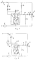
- FIGS. 1 to 8 show circuit arrangements of a Leading edge control circuit and with a current limiting circuit.
- An electrical consumer in particular a motor 1, which, for example, as Blower motor used in a vacuum cleaner, one is controllable Semiconductor switching element 2 controlled or regulated in its performance.
- the Semiconductor switching element 2 is with its control connection 3 to one Power supply connected by a leading edge control circuit is formed.
- a switch 4 is arranged, the with a power terminal 5 is connected.
- the control terminal 3 of the semiconductor switching element 2 via a potentiometer 6 and over to this in series resistors 7, 8 and 9 and a diac 10th supplied with voltage as a control element, so that it is in both half-waves through mains AC voltage to motor 1.
- a capacitor 12 is arranged in parallel with the resistor 9, the diac 10 and the semiconductor switching element 2.
- the capacitor 12 is after Switch on the voltage via the switch 4 via the potentiometer 6 and the resistors 7 and 8 depending on the position of the potentiometer 6 more or charged less quickly. Reaches the voltage across capacitor 12 irrespective of their polarity, the breakdown voltage of the diac 10 is so this conductive, so that the capacitor 12 over a certain time the resistor 9 discharges until the control terminal 3 and one Main terminal 13 of the semiconductor switching element 2 a load current to one Terminal 14 of the motor 1 flows.
- the semiconductor switching element 2 is conductive as long as a certain one Current, the so-called holding current, flows through it. It is from the two half-waves of the AC signal according to the position of the Potentiometers 6 only use a certain phase angle to motor 1 to drive.
- the current limiting circuit 16 has therefore one consisting of four diodes 17, 18, 19 and 20 Bridge rectifier circuit, with diodes 17 and 18 or 19 and 20 are each arranged so that they are opposed to each other Half waves of the AC voltage is permeable.
- a Zener diode 21 and a Electrolytic capacitor 22 and a resistor 23 are arranged.
- the electrolytic capacitor 22 is only with direct voltage supplied, the Zener diode 21 the voltage for charging the electrolytic capacitor 22 limited. How the control limiting circuit works 16 is thus that initially until the Zener diode 21 maximum permitted voltage of the electrolytic capacitor 22 is charged and the capacitor 12 is charged only after this voltage has been exceeded.
- the resistor 23 serves as a discharge resistor for the Electrolytic capacitor 22.
- the current limiting circuit 16 since the current limiting circuit 16 in turn consumes current, it is only in the time after switching on the network or after a Increased performance of the consumer desires that the hysteresis effect of Phase gating control circuit is limited. After a period of time, which depending on the dimensioning of resistors 7, 8 and 9 as well the position of the potentiometer 6 is different, according to the invention Current limiting circuit 16 turned off, including a between the bridge point 15 and the input of the current limiting circuit 16 arranged switch 24 is provided.
- a switch 26 instead of the switch 24 is between the output of the current limiting circuit 16 and a bridge connection point 25, a switch 26 provided (Fig. 2).
- a switch 27 is together with a resistor 28 connected in parallel to the resistors 7 and 8.
- a switch 29 (Fig. 4) switches the AC voltage either through the resistor 7 to the current limiting circuit 16, for example after switching on the circuit or in the event of a strong change in performance, or the switch 29 switches the potentiometer 6 in series with the resistor 28 so that the current limiting circuit 16 is bypassed and the capacitor 12 is loaded immediately.
- the switch 27 shown in FIG. 3 is in a preferred embodiment (Fig. 5) designed as a vacuum switch 27a. If the engine 14 as Blower motor, for example, in a vacuum cleaner, is a with the vacuum switch 27a related vacuum sensor in Suction part of the blower arranged so that after falling below a predetermined pressure of the vacuum switch 27a closes, whereby the Current limiting circuit 16 is bypassed.
- the switch 27 is in a further embodiment (Fig. 6) temperature-dependent switch 27b formed.
- the switch 27b is for example, a resistance that decreases with temperature, so preferably a PTC or an NTC resistor that increases with temperature decreases, so that the current path between the potentiometer 6 and the Bridge circuit point 11 becomes conductive.
- FIG. 7 it is provided that after the Turn on the switch 4, the current first over a parallel to the Potentiometer 6 arranged resistor 30 flows, the path to the Current limiting circuit 16 is free, ensuring that the motor 1st during the switch-on phase regardless of the position of the potentiometer 6 is supplied with a fixed predetermined voltage, which corresponds to the Dimensioning of the resistors 30, 9 and one additional before Bridge circuit point 11 arranged resistor 31 results. Only after Exceeding a certain temperature, for example the temperature in the The area of the stator winding of the motor 1 becomes a in series with the potentiometer 6 arranged resistor 32 acted upon by this temperature electrically conductive, so that the potentiometer 6 can be operated effectively by the operator.
- FIG. 8 there is a switch instead of the switch 4 33 provided with a time-delayed contact 34.
- the contact 34 switches after a certain predetermined period of time the resistor 28 comprehensive current path to the control terminal 3, so that the Current limiting circuit 16 is bypassed.
- thermoelectric switches for example in the form of NTC or PTC resistors or as bimetallic switches.
- thermoelectric switches for example in the form of NTC or PTC resistors or as bimetallic switches.
- other switching means that one or more operating variables of the electrical consumer after successful startup or after successful Evaluate the increase in power and activate the current paths accordingly which bypasses the current limiting circuit 16.
- Sizing is also suitable in addition to the temperature, pressure or negative pressure the voltage or current within the circuit.
- the invention can be applied universally to all motorized devices with a motor, for example use a universal motor and one with a current limit, it being sufficient if the current limiting circuit consists of an RC element exists, which is connected in parallel to the phase control circuit. By the use of the invention, voltage losses through the Current limiting circuit minimized.
Landscapes
- Engineering & Computer Science (AREA)
- Power Engineering (AREA)
- Electric Vacuum Cleaner (AREA)
- Motor And Converter Starters (AREA)
- Control Of Ac Motors In General (AREA)
Applications Claiming Priority (2)
| Application Number | Priority Date | Filing Date | Title |
|---|---|---|---|
| DE1999137626 DE19937626A1 (de) | 1999-08-10 | 1999-08-10 | Schaltungsanordnung zur Leistungssteuerung eines elektrischen Verbrauchers |
| DE19937626 | 1999-08-10 |
Publications (3)
| Publication Number | Publication Date |
|---|---|
| EP1076409A2 true EP1076409A2 (fr) | 2001-02-14 |
| EP1076409A3 EP1076409A3 (fr) | 2002-11-27 |
| EP1076409B1 EP1076409B1 (fr) | 2010-09-15 |
Family
ID=7917781
Family Applications (1)
| Application Number | Title | Priority Date | Filing Date |
|---|---|---|---|
| EP00116042A Expired - Lifetime EP1076409B1 (fr) | 1999-08-10 | 2000-07-26 | Circuit pour la commande de puissance d'un consommateur électrique |
Country Status (2)
| Country | Link |
|---|---|
| EP (1) | EP1076409B1 (fr) |
| DE (2) | DE19937626A1 (fr) |
Families Citing this family (1)
| Publication number | Priority date | Publication date | Assignee | Title |
|---|---|---|---|---|
| DE102017206538A1 (de) * | 2017-04-18 | 2018-10-18 | Mahle International Gmbh | Elektrische Gleichstrommaschine |
Citations (8)
| Publication number | Priority date | Publication date | Assignee | Title |
|---|---|---|---|---|
| DE2539543A1 (de) | 1975-09-05 | 1977-03-10 | Heinz Georg Ostwald | Vorschaltgeraet fuer stromverbraucher |
| DE2746845A1 (de) | 1977-10-19 | 1979-04-26 | Bsg Schalttechnik | Einrichtung zur einschaltstrombegrenzung fuer wechselspannungsbetriebene verbraucher |
| DE2935807A1 (de) | 1979-09-05 | 1981-04-02 | Brown, Boveri & Cie Ag, 6800 Mannheim | Einrichtung zum schutz von elektrischen geraeten gegen ueberlastung |
| DE3444745A1 (de) | 1984-12-07 | 1986-06-12 | Siemens AG, 1000 Berlin und 8000 München | Schaltungsanordnung zur begrenzung des anlaufstromes eines motors |
| DD286912A5 (de) | 1989-08-11 | 1991-02-07 | Veb Elektroinstallation Oberlind,De | Elektronische sanftanlaufschaltung, insbesondere fuer motore von bodenstaubsaugern |
| DE4233542C1 (de) | 1992-10-06 | 1994-01-05 | Bsg Schalttechnik | Vorrichtung zur Einschaltstrombegrenzung (Sanftanlaufschaltung) |
| EP0678271A2 (fr) | 1994-04-21 | 1995-10-25 | Siemens Aktiengesellschaft | Circuit pour régler la puissance d'aspiration d'un aspirateur de poussière |
| DE19755368A1 (de) | 1996-12-27 | 1998-07-02 | Makita Corp | Startvorrichtung für einen Elektromotor |
Family Cites Families (1)
| Publication number | Priority date | Publication date | Assignee | Title |
|---|---|---|---|---|
| US4422030A (en) * | 1980-08-15 | 1983-12-20 | Mcallise Raymond J | A.C. Motor control |
-
1999
- 1999-08-10 DE DE1999137626 patent/DE19937626A1/de not_active Withdrawn
-
2000
- 2000-07-26 EP EP00116042A patent/EP1076409B1/fr not_active Expired - Lifetime
- 2000-07-26 DE DE50015991T patent/DE50015991D1/de not_active Expired - Lifetime
Patent Citations (8)
| Publication number | Priority date | Publication date | Assignee | Title |
|---|---|---|---|---|
| DE2539543A1 (de) | 1975-09-05 | 1977-03-10 | Heinz Georg Ostwald | Vorschaltgeraet fuer stromverbraucher |
| DE2746845A1 (de) | 1977-10-19 | 1979-04-26 | Bsg Schalttechnik | Einrichtung zur einschaltstrombegrenzung fuer wechselspannungsbetriebene verbraucher |
| DE2935807A1 (de) | 1979-09-05 | 1981-04-02 | Brown, Boveri & Cie Ag, 6800 Mannheim | Einrichtung zum schutz von elektrischen geraeten gegen ueberlastung |
| DE3444745A1 (de) | 1984-12-07 | 1986-06-12 | Siemens AG, 1000 Berlin und 8000 München | Schaltungsanordnung zur begrenzung des anlaufstromes eines motors |
| DD286912A5 (de) | 1989-08-11 | 1991-02-07 | Veb Elektroinstallation Oberlind,De | Elektronische sanftanlaufschaltung, insbesondere fuer motore von bodenstaubsaugern |
| DE4233542C1 (de) | 1992-10-06 | 1994-01-05 | Bsg Schalttechnik | Vorrichtung zur Einschaltstrombegrenzung (Sanftanlaufschaltung) |
| EP0678271A2 (fr) | 1994-04-21 | 1995-10-25 | Siemens Aktiengesellschaft | Circuit pour régler la puissance d'aspiration d'un aspirateur de poussière |
| DE19755368A1 (de) | 1996-12-27 | 1998-07-02 | Makita Corp | Startvorrichtung für einen Elektromotor |
Also Published As
| Publication number | Publication date |
|---|---|
| EP1076409B1 (fr) | 2010-09-15 |
| DE50015991D1 (de) | 2010-10-28 |
| DE19937626A1 (de) | 2001-02-15 |
| EP1076409A3 (fr) | 2002-11-27 |
Similar Documents
| Publication | Publication Date | Title |
|---|---|---|
| AT402355B (de) | Elektronische anlassschaltung für einen einphasen-induktionsmotor | |
| DE102004046823B3 (de) | Elektronisches Schaltgerät, insbesondere Leistungsschalter, und zugehörige Betriebsweise | |
| CH662907A5 (de) | Elektronische kupplung fuer elektrowerkzeuge mit waehlbarer drehzahl. | |
| DE19620019A1 (de) | Kostengünstige Softstart-Anordnung mit hoher Verläßlichkeit | |
| EP2850629B1 (fr) | Commutateur électrique | |
| EP2220737B1 (fr) | Circuit pour faire fonctionner un appareil électroménager | |
| EP1568122B1 (fr) | Dispositif et procede permettant de reduire la consommation de courant au demarrage d'un moteur asynchrone a courant alternatif monophase | |
| DE2746845C2 (de) | Einrichtung zur Wechselstrom-Einschaltstrombegrenzung | |
| DE3303126C2 (fr) | ||
| EP2539912B1 (fr) | Configuration de circuit pour faire fonctionner un appareil électroménager, et procédé correspondant | |
| EP1076409B1 (fr) | Circuit pour la commande de puissance d'un consommateur électrique | |
| DE102011110929A1 (de) | Hand-Werkzeugmaschine mit einer elektrischen Bremseinrichtung | |
| EP0877470A2 (fr) | Procédé et dispositif de commande de puissance pour une charge électrique connectée à un réseau d'alimentation en courant alternatif | |
| DE3248217A1 (de) | Vorrichtung zur temperaturabhaengigen elektromotor-steuerung | |
| DE102016117273B4 (de) | Relais mit einer Steuerung und Verfahren zur Steuerung eines Relais | |
| DE602004011536T2 (de) | Leistungsregler | |
| EP1101266B1 (fr) | Circuit pour la limitation du courant d'appel d'un transformateur | |
| DE19718814C2 (de) | Verfahren und Vorrichtung zur Leistungsssteuerung von an ein Wechselspannungs-Versorgungsnetz angeschlossenen elektrischen Verbrauchern | |
| DE3622093C1 (en) | Switch arrangement for supplying a load with alternating current | |
| WO2004082334A1 (fr) | Appareil chauffant presentant une partie souple degageant de la chaleur | |
| EP1875590B1 (fr) | Commande a phases | |
| DE4233542C1 (de) | Vorrichtung zur Einschaltstrombegrenzung (Sanftanlaufschaltung) | |
| EP0500024B1 (fr) | Relais à impulsion | |
| EP1253809A2 (fr) | Organe de commande et méthode de commande d' une charge électrique | |
| DE102011001995A1 (de) | Anlaufschaltung für einen Wechselspannungsmotor |
Legal Events
| Date | Code | Title | Description |
|---|---|---|---|
| PUAI | Public reference made under article 153(3) epc to a published international application that has entered the european phase |
Free format text: ORIGINAL CODE: 0009012 |
|
| AK | Designated contracting states |
Kind code of ref document: A2 Designated state(s): AT BE CH CY DE DK ES FI FR GB GR IE IT LI LU MC NL PT SE |
|
| AX | Request for extension of the european patent |
Free format text: AL;LT;LV;MK;RO;SI |
|
| PUAL | Search report despatched |
Free format text: ORIGINAL CODE: 0009013 |
|
| AK | Designated contracting states |
Kind code of ref document: A3 Designated state(s): AT BE CH CY DE DK ES FI FR GB GR IE IT LI LU MC NL PT SE |
|
| AX | Request for extension of the european patent |
Free format text: AL;LT;LV;MK;RO;SI |
|
| RIC1 | Information provided on ipc code assigned before grant |
Free format text: 7H 02P 3/06 A, 7H 02H 9/00 B |
|
| 17P | Request for examination filed |
Effective date: 20030527 |
|
| AKX | Designation fees paid |
Designated state(s): DE FR IT SE |
|
| RAP1 | Party data changed (applicant data changed or rights of an application transferred) |
Owner name: BSH BOSCH UND SIEMENS HAUSGERAETE GMBH |
|
| 17Q | First examination report despatched |
Effective date: 20080822 |
|
| GRAP | Despatch of communication of intention to grant a patent |
Free format text: ORIGINAL CODE: EPIDOSNIGR1 |
|
| RIN1 | Information on inventor provided before grant (corrected) |
Inventor name: FREUND, ELMAR Inventor name: STREHLER, THOMAS |
|
| GRAS | Grant fee paid |
Free format text: ORIGINAL CODE: EPIDOSNIGR3 |
|
| GRAA | (expected) grant |
Free format text: ORIGINAL CODE: 0009210 |
|
| AK | Designated contracting states |
Kind code of ref document: B1 Designated state(s): DE FR IT SE |
|
| REF | Corresponds to: |
Ref document number: 50015991 Country of ref document: DE Date of ref document: 20101028 Kind code of ref document: P |
|
| PG25 | Lapsed in a contracting state [announced via postgrant information from national office to epo] |
Ref country code: SE Free format text: LAPSE BECAUSE OF FAILURE TO SUBMIT A TRANSLATION OF THE DESCRIPTION OR TO PAY THE FEE WITHIN THE PRESCRIBED TIME-LIMIT Effective date: 20100915 |
|
| PG25 | Lapsed in a contracting state [announced via postgrant information from national office to epo] |
Ref country code: IT Free format text: LAPSE BECAUSE OF FAILURE TO SUBMIT A TRANSLATION OF THE DESCRIPTION OR TO PAY THE FEE WITHIN THE PRESCRIBED TIME-LIMIT Effective date: 20100915 |
|
| PLBE | No opposition filed within time limit |
Free format text: ORIGINAL CODE: 0009261 |
|
| STAA | Information on the status of an ep patent application or granted ep patent |
Free format text: STATUS: NO OPPOSITION FILED WITHIN TIME LIMIT |
|
| 26N | No opposition filed |
Effective date: 20110616 |
|
| REG | Reference to a national code |
Ref country code: DE Ref legal event code: R097 Ref document number: 50015991 Country of ref document: DE Effective date: 20110616 |
|
| REG | Reference to a national code |
Ref country code: FR Ref legal event code: ST Effective date: 20120330 |
|
| PG25 | Lapsed in a contracting state [announced via postgrant information from national office to epo] |
Ref country code: FR Free format text: LAPSE BECAUSE OF NON-PAYMENT OF DUE FEES Effective date: 20110801 |
|
| REG | Reference to a national code |
Ref country code: DE Ref legal event code: R081 Ref document number: 50015991 Country of ref document: DE Owner name: BSH HAUSGERAETE GMBH, DE Free format text: FORMER OWNER: BSH BOSCH UND SIEMENS HAUSGERAETE GMBH, 81739 MUENCHEN, DE Effective date: 20150402 |
|
| PGFP | Annual fee paid to national office [announced via postgrant information from national office to epo] |
Ref country code: DE Payment date: 20170731 Year of fee payment: 18 |
|
| REG | Reference to a national code |
Ref country code: DE Ref legal event code: R119 Ref document number: 50015991 Country of ref document: DE |
|
| PG25 | Lapsed in a contracting state [announced via postgrant information from national office to epo] |
Ref country code: DE Free format text: LAPSE BECAUSE OF NON-PAYMENT OF DUE FEES Effective date: 20190201 |