EP0678285B1 - Procédé pour fabriquer un implant orthopédique - Google Patents
Procédé pour fabriquer un implant orthopédique Download PDFInfo
- Publication number
- EP0678285B1 EP0678285B1 EP95200930A EP95200930A EP0678285B1 EP 0678285 B1 EP0678285 B1 EP 0678285B1 EP 95200930 A EP95200930 A EP 95200930A EP 95200930 A EP95200930 A EP 95200930A EP 0678285 B1 EP0678285 B1 EP 0678285B1
- Authority
- EP
- European Patent Office
- Prior art keywords
- porous
- implant
- pad
- metal foil
- porous pad
- Prior art date
- Legal status (The legal status is an assumption and is not a legal conclusion. Google has not performed a legal analysis and makes no representation as to the accuracy of the status listed.)
- Expired - Lifetime
Links
Images

Classifications
-
- A—HUMAN NECESSITIES
- A61—MEDICAL OR VETERINARY SCIENCE; HYGIENE
- A61F—FILTERS IMPLANTABLE INTO BLOOD VESSELS; PROSTHESES; DEVICES PROVIDING PATENCY TO, OR PREVENTING COLLAPSING OF, TUBULAR STRUCTURES OF THE BODY, e.g. STENTS; ORTHOPAEDIC, NURSING OR CONTRACEPTIVE DEVICES; FOMENTATION; TREATMENT OR PROTECTION OF EYES OR EARS; BANDAGES, DRESSINGS OR ABSORBENT PADS; FIRST-AID KITS
- A61F2/00—Filters implantable into blood vessels; Prostheses, i.e. artificial substitutes or replacements for parts of the body; Appliances for connecting them with the body; Devices providing patency to, or preventing collapsing of, tubular structures of the body, e.g. stents
- A61F2/02—Prostheses implantable into the body
- A61F2/30—Joints
- A61F2/30767—Special external or bone-contacting surface, e.g. coating for improving bone ingrowth
- A61F2/30907—Nets or sleeves applied to surface of prostheses or in cement
-
- A—HUMAN NECESSITIES
- A61—MEDICAL OR VETERINARY SCIENCE; HYGIENE
- A61F—FILTERS IMPLANTABLE INTO BLOOD VESSELS; PROSTHESES; DEVICES PROVIDING PATENCY TO, OR PREVENTING COLLAPSING OF, TUBULAR STRUCTURES OF THE BODY, e.g. STENTS; ORTHOPAEDIC, NURSING OR CONTRACEPTIVE DEVICES; FOMENTATION; TREATMENT OR PROTECTION OF EYES OR EARS; BANDAGES, DRESSINGS OR ABSORBENT PADS; FIRST-AID KITS
- A61F2/00—Filters implantable into blood vessels; Prostheses, i.e. artificial substitutes or replacements for parts of the body; Appliances for connecting them with the body; Devices providing patency to, or preventing collapsing of, tubular structures of the body, e.g. stents
- A61F2/02—Prostheses implantable into the body
- A61F2/30—Joints
- A61F2/3094—Designing or manufacturing processes
-
- A—HUMAN NECESSITIES
- A61—MEDICAL OR VETERINARY SCIENCE; HYGIENE
- A61F—FILTERS IMPLANTABLE INTO BLOOD VESSELS; PROSTHESES; DEVICES PROVIDING PATENCY TO, OR PREVENTING COLLAPSING OF, TUBULAR STRUCTURES OF THE BODY, e.g. STENTS; ORTHOPAEDIC, NURSING OR CONTRACEPTIVE DEVICES; FOMENTATION; TREATMENT OR PROTECTION OF EYES OR EARS; BANDAGES, DRESSINGS OR ABSORBENT PADS; FIRST-AID KITS
- A61F2/00—Filters implantable into blood vessels; Prostheses, i.e. artificial substitutes or replacements for parts of the body; Appliances for connecting them with the body; Devices providing patency to, or preventing collapsing of, tubular structures of the body, e.g. stents
- A61F2/02—Prostheses implantable into the body
- A61F2/30—Joints
- A61F2/32—Joints for the hip
- A61F2/36—Femoral heads ; Femoral endoprostheses
- A61F2/3662—Femoral shafts
-
- A—HUMAN NECESSITIES
- A61—MEDICAL OR VETERINARY SCIENCE; HYGIENE
- A61F—FILTERS IMPLANTABLE INTO BLOOD VESSELS; PROSTHESES; DEVICES PROVIDING PATENCY TO, OR PREVENTING COLLAPSING OF, TUBULAR STRUCTURES OF THE BODY, e.g. STENTS; ORTHOPAEDIC, NURSING OR CONTRACEPTIVE DEVICES; FOMENTATION; TREATMENT OR PROTECTION OF EYES OR EARS; BANDAGES, DRESSINGS OR ABSORBENT PADS; FIRST-AID KITS
- A61F2/00—Filters implantable into blood vessels; Prostheses, i.e. artificial substitutes or replacements for parts of the body; Appliances for connecting them with the body; Devices providing patency to, or preventing collapsing of, tubular structures of the body, e.g. stents
- A61F2/02—Prostheses implantable into the body
- A61F2/30—Joints
- A61F2/38—Joints for elbows or knees
- A61F2/389—Tibial components
-
- A—HUMAN NECESSITIES
- A61—MEDICAL OR VETERINARY SCIENCE; HYGIENE
- A61F—FILTERS IMPLANTABLE INTO BLOOD VESSELS; PROSTHESES; DEVICES PROVIDING PATENCY TO, OR PREVENTING COLLAPSING OF, TUBULAR STRUCTURES OF THE BODY, e.g. STENTS; ORTHOPAEDIC, NURSING OR CONTRACEPTIVE DEVICES; FOMENTATION; TREATMENT OR PROTECTION OF EYES OR EARS; BANDAGES, DRESSINGS OR ABSORBENT PADS; FIRST-AID KITS
- A61F2/00—Filters implantable into blood vessels; Prostheses, i.e. artificial substitutes or replacements for parts of the body; Appliances for connecting them with the body; Devices providing patency to, or preventing collapsing of, tubular structures of the body, e.g. stents
- A61F2/02—Prostheses implantable into the body
- A61F2/30—Joints
- A61F2002/30001—Additional features of subject-matter classified in A61F2/28, A61F2/30 and subgroups thereof
- A61F2002/30316—The prosthesis having different structural features at different locations within the same prosthesis; Connections between prosthetic parts; Special structural features of bone or joint prostheses not otherwise provided for
- A61F2002/30329—Connections or couplings between prosthetic parts, e.g. between modular parts; Connecting elements
- A61F2002/30451—Connections or couplings between prosthetic parts, e.g. between modular parts; Connecting elements soldered or brazed or welded
-
- A—HUMAN NECESSITIES
- A61—MEDICAL OR VETERINARY SCIENCE; HYGIENE
- A61F—FILTERS IMPLANTABLE INTO BLOOD VESSELS; PROSTHESES; DEVICES PROVIDING PATENCY TO, OR PREVENTING COLLAPSING OF, TUBULAR STRUCTURES OF THE BODY, e.g. STENTS; ORTHOPAEDIC, NURSING OR CONTRACEPTIVE DEVICES; FOMENTATION; TREATMENT OR PROTECTION OF EYES OR EARS; BANDAGES, DRESSINGS OR ABSORBENT PADS; FIRST-AID KITS
- A61F2/00—Filters implantable into blood vessels; Prostheses, i.e. artificial substitutes or replacements for parts of the body; Appliances for connecting them with the body; Devices providing patency to, or preventing collapsing of, tubular structures of the body, e.g. stents
- A61F2/02—Prostheses implantable into the body
- A61F2/30—Joints
- A61F2/3094—Designing or manufacturing processes
- A61F2002/30975—Designing or manufacturing processes made of two halves
-
- A—HUMAN NECESSITIES
- A61—MEDICAL OR VETERINARY SCIENCE; HYGIENE
- A61F—FILTERS IMPLANTABLE INTO BLOOD VESSELS; PROSTHESES; DEVICES PROVIDING PATENCY TO, OR PREVENTING COLLAPSING OF, TUBULAR STRUCTURES OF THE BODY, e.g. STENTS; ORTHOPAEDIC, NURSING OR CONTRACEPTIVE DEVICES; FOMENTATION; TREATMENT OR PROTECTION OF EYES OR EARS; BANDAGES, DRESSINGS OR ABSORBENT PADS; FIRST-AID KITS
- A61F2220/00—Fixations or connections for prostheses classified in groups A61F2/00 - A61F2/26 or A61F2/82 or A61F9/00 or A61F11/00 or subgroups thereof
- A61F2220/0025—Connections or couplings between prosthetic parts, e.g. between modular parts; Connecting elements
- A61F2220/0058—Connections or couplings between prosthetic parts, e.g. between modular parts; Connecting elements soldered or brazed or welded
-
- A—HUMAN NECESSITIES
- A61—MEDICAL OR VETERINARY SCIENCE; HYGIENE
- A61F—FILTERS IMPLANTABLE INTO BLOOD VESSELS; PROSTHESES; DEVICES PROVIDING PATENCY TO, OR PREVENTING COLLAPSING OF, TUBULAR STRUCTURES OF THE BODY, e.g. STENTS; ORTHOPAEDIC, NURSING OR CONTRACEPTIVE DEVICES; FOMENTATION; TREATMENT OR PROTECTION OF EYES OR EARS; BANDAGES, DRESSINGS OR ABSORBENT PADS; FIRST-AID KITS
- A61F2310/00—Prostheses classified in A61F2/28 or A61F2/30 - A61F2/44 being constructed from or coated with a particular material
- A61F2310/00389—The prosthesis being coated or covered with a particular material
- A61F2310/00395—Coating or prosthesis-covering structure made of metals or of alloys
-
- B—PERFORMING OPERATIONS; TRANSPORTING
- B23—MACHINE TOOLS; METAL-WORKING NOT OTHERWISE PROVIDED FOR
- B23K—SOLDERING OR UNSOLDERING; WELDING; CLADDING OR PLATING BY SOLDERING OR WELDING; CUTTING BY APPLYING HEAT LOCALLY, e.g. FLAME CUTTING; WORKING BY LASER BEAM
- B23K2103/00—Materials to be soldered, welded or cut
- B23K2103/30—Organic materials
- B23K2103/42—Plastics other than composite materials
-
- B—PERFORMING OPERATIONS; TRANSPORTING
- B23—MACHINE TOOLS; METAL-WORKING NOT OTHERWISE PROVIDED FOR
- B23K—SOLDERING OR UNSOLDERING; WELDING; CLADDING OR PLATING BY SOLDERING OR WELDING; CUTTING BY APPLYING HEAT LOCALLY, e.g. FLAME CUTTING; WORKING BY LASER BEAM
- B23K2103/00—Materials to be soldered, welded or cut
- B23K2103/50—Inorganic materials other than metals or composite materials
-
- Y—GENERAL TAGGING OF NEW TECHNOLOGICAL DEVELOPMENTS; GENERAL TAGGING OF CROSS-SECTIONAL TECHNOLOGIES SPANNING OVER SEVERAL SECTIONS OF THE IPC; TECHNICAL SUBJECTS COVERED BY FORMER USPC CROSS-REFERENCE ART COLLECTIONS [XRACs] AND DIGESTS
- Y10—TECHNICAL SUBJECTS COVERED BY FORMER USPC
- Y10S—TECHNICAL SUBJECTS COVERED BY FORMER USPC CROSS-REFERENCE ART COLLECTIONS [XRACs] AND DIGESTS
- Y10S623/00—Prosthesis, i.e. artificial body members, parts thereof, or aids and accessories therefor
- Y10S623/901—Method of manufacturing prosthetic device
-
- Y—GENERAL TAGGING OF NEW TECHNOLOGICAL DEVELOPMENTS; GENERAL TAGGING OF CROSS-SECTIONAL TECHNOLOGIES SPANNING OVER SEVERAL SECTIONS OF THE IPC; TECHNICAL SUBJECTS COVERED BY FORMER USPC CROSS-REFERENCE ART COLLECTIONS [XRACs] AND DIGESTS
- Y10—TECHNICAL SUBJECTS COVERED BY FORMER USPC
- Y10S—TECHNICAL SUBJECTS COVERED BY FORMER USPC CROSS-REFERENCE ART COLLECTIONS [XRACs] AND DIGESTS
- Y10S623/00—Prosthesis, i.e. artificial body members, parts thereof, or aids and accessories therefor
- Y10S623/92—Method or apparatus for preparing or treating prosthetic
- Y10S623/923—Bone
Definitions
- This invention relates to orthopaedic implants having a porous outer layer and has specific relevance to an implant having a porous layer attached to the implant body by welding.
- orthopaedic implant manufactures may either limit the amount of the porous layer attached to the substrate or adjust the size of the substrate to increase its strength.
- the method and implant of this invention provide for the attachment of a porous pad to the implant by laser welding.
- the porous pad is comprised of a flat sheet of porous material that is diffusion bonded to a thin metal foil layer. Diffusion bonding between the flat foil to the porous material is substantially less troublesome than when bonding on a curved surface.
- the pad is cut to the desired shape to form a blank. The blank is stamped into a shape substantially conforming to its intended location on the implant. The blank is positioned on the implant and laser welded to the substrate. If the porous surface is intended to surround a portion of the implant such as would be seem on a porous hip stem, a second blank is cut and stamped.
- the two stamped blanks are positioned about the implant such that they abut at their edges.
- the blanks are then welded together using a laser welder to form an integral porous layer about the implant.
- the porous pads may also be welded using the laser welder to the implant at their ends to seal the interface of the porous pad and implant.
- a polymer layer could be positioned between the pad and substrate.
- the polymer layer would adhesively bond the pad and substrate together to eliminate the need for unique wilting clamps and also would assist in transferring stress to the substrate in a more uniform manner.
- the polymer would also assist in filling gaps between the pad and the substrate thereby allowing the manufacturer to reduce the manufacturing tolerances for the substrate and pad.
- the thin metal foil may include small holes to allow the ingress and egress of fluid from the space between the pad and substrate.
- laser weld laser welder or laser beam are used throughout this application to refer to any high energy density welding process such as laser or electron beam welding.
- Another advantage of the invention is to provide for a novel method of attaching a porous surface to an orthopaedic implant.
- Yet another advantage of the invention is to provide a method of attaching a porous surface to an implant without detrimentally effecting the strength of the implant.
- Another advantage of the invention is to provide an orthopaedic implant wherein the interface between the porous surface layer and the implant body is sealed.
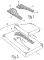
- Fig. 1 is a perspective view of a substantially flat porous blank for a hip stem implant which has been cut from a larger porous pad.
- Fig. 2 is a perspective view illustrating the stamping process used to form the flat porous blank of Fig. 1 into the shape to fit a portion of a hip stem implant.
- Fig. 3 is an exploded perspective view of a hip stem configured for accepting the shaped blanks of Fig. 2.
- Fig. 4 is a perspective view of the hip stem and blanks of Fig. 3 after the welding process is complete.
- Fig. 5 is a cross-sectional view taken along lines 5-5 of Fig. 4.
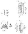
- Fig. 6 is an elevational view of a substantially flat blank formed in an alternative manner such that the metal foil extends beyond the porous material.
- Fig. 7 is a side elevational view of Fig. 6.
- Figs. 8 and 9 illustrate the shaping of the substantially flat blank of Figs. 6 and 7 with a stamping die such that the foil extends along the side edges of the porous material.
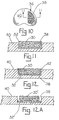
- Fig. 10 is an elevational view illustrating the porous pad of Figs. 6 through 10 positioned within a recess of a tibial plate.
- Fig. 11 is a cross sectional view taken along lines 11-11 of Fig. 10 and prior to welding.
- Fig. 12 illustrates the cross-sectional view of Fig. 11 after the porous pad has been laser welded to the implant.
- Fig. 12A illustrates an alternative method wherein the pad of Fig. 7 is placed into the recess and welded thereto without bending the extending edges upwardly.
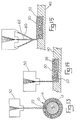
- Fig. 13 is a diagram illustrating the method of laser welding the porous pads to an implant.
- the implant and porous pads are illustrated in cross-section.
- Fig. 14 is an enlarged cross sectional view of the area circled in Fig. 10 and identified by number 14.
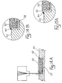
- Fig. 14A is a diagram illustrating the method of laser welding the porous pads within the recess of an implant (only partially shown).
- Fig. 14B is the enlarged cross sectional view of Fig. 14 after the porous pad has been welded to the implant.
- Fig. 15 is a diagram illustrating a method for laser cladding the porous pads to the implant.
- Fig. 15A is an enlarged cross sectional view illustrating the cladded junction between the porous pad and the implant.
- the methods of the invention are illustrated in the figures to yield an implant having a porous structure welded to the body of the implant.
- the method begins with the formation of a porous pad 10 having a porous surface 12 and a thin metal backing 14.
- a large sheet of the porous material such as fiber metal, is diffusion bonded to a similarly sized thin metal sheet or foil.
- blanks 8 are cut from the sheet using laser cutting or a device which can cut through the pad without substantially deforming the edges of the blank. Blanks 8 are then placed within a stamping die 16 having cooperating male and female sections as illustrated in Fig. 2.
- Stamping die 16 includes cooperating male and female parts which come together under force and forms the blanks 8 into pads 10 which substantially conform to a portion of hip implant 17 as shown in Fig. 3.
- implant 17 includes a stem portion 16 which includes a reduced section forming shoulders 18 and 20. The reduced section is provided to accommodate the blanks.
- Shoulders 18 and 20 are provided to abut the distal and proximal ends of the blanks and assist in preventing the shaped pads 10 from shifting longitudinally relative to the implant 17.
- the pads are placed onto the implant and temporarily held in place by a clamp device (not shown).
- a quantity of an adhesive polymer could be placed between the pads and stem to hold the pads in place during welding.
- the polymer would also assist in transferring the load to the stem in use.
- a laser is guided along the seams between the pads 10 forming a weld bead 22 to cause a portion of the pads to melt together thereby forming an integral pad about the body of the implant.
- the intensity of the laser may be controlled to precisely control the depth of the weld bead.
- the intensity of the weld bead is set such that the bead is formed only between the porous pads and does not invade the outer surface of the implant. Once welded, the porous pads are securely held between the shoulders 18, 20 of the implant.
- the laser welder may be guided around the proximal and distal shoulder of the implant to weld the pad to the shoulder of the implant. Therefore, the interface between the pad and the implant is sealed by the laser weld. The sealing of the interface between the pad and the implant would prevent the ingress of the body fluids.
- FIG. 6-12 An alternative method is illustrated in Figs 6 through 12.
- the porous material 30, preferably fiber metal is cut to shape and then diffusion bonded to a thin metal foil 32 having a similar shape.
- the metal foil is slightly larger than the porous material and extends outwardly therefrom as illustrated.
- the fiber metal 30 and foil 32 are diffusion bonded in a known manner and are then placed into a stamping die 34 and stamped such that the portion of the foil extending outwardly from the fiber metal is bent around the side edges of the fiber metal as illustrated in Figs. 8 and 9 to form a fiber metal pad 36 a foil bottom portion and side portions.
- the fiber metal pad 36 is placed within a matching recess 38 of an implant.
- the fiber metal pad 30 is shown positioned within a matching recess 38 on the bone engaging surface of a tibial knee component 40 (partially illustrated). As illustrated, the fiber metal pad stands proud relative to the implant with the foil extending slightly above the implant surface. The small amount of foil extending above the implant provides the material which forms the weld bead 42 during the welding process. After positioning in the matching recess, the pad is laser welded to the implant at the junction between the implant and the foil along the edge of the pad. Figure 12 illustrates the pad 36 after welding to the implant. The weld may be directed completely around the periphery of the fiber metal pad thereby sealing the area between the pad and the implant from the ingress of moisture. Further, the pad may be formed with openings to accommodate screw holes or fixation posts as are well known in the industry. Using the laser welding technique of the invention, the pad may be welded about such openings to enhance fixation of the pad to the implant.
- the stamping process is eliminated. Therefore, as illustrated in Fig. 12A, the foil 32' extends beyond the fiber metal layer 30' a predetermined amount but is shaped so as to closely approximate the cavity 38 formed in the implant 40.
- the laser beam is directed along the extending portion of the foil to secure the foil to the implant along the weld bead as illustrated in Fig. 12A.
- Figure 13 illustrates in diagram form the laser welding of the hip stem of Figs. 1 through 5.
- the particular type of laser welder used is one of choice to the manufacturer and are commercially available. Given that laser welding in general is known, it will not be discussed here. What is important is that the power or intensity of the laser can be controlled such that the laser beam only affects the fiber metal pad locally and does not extend into implant substrate. Laser welding radiates less heat to the body of the implant than other welding techniques such as plasma or arc welding. Therefore the use of the laser is the preferred method to ensure that the metallurgy of the implant is not detrimentally changed by the welding process.
- Figures 14 and 14A illustrate in diagram form the laser welding of the fiber metal pad of Figs. 6 through 12.
- the welding process is joining the metal foil to the implant, some deformation of the implant is necessary to effect the weld.
- the laser welder 50 by use of the laser welder 50, the extent of the deformation will be localized along the weld bead, thereby preventing detrimental metallurgical changes in the implant body.
- a portion of the foil 32 extends above the implant surface and forms the material used in the welding process to form the weld bead 42.
- Figure 14B illustrates the section of 14A after the welding process is completed.
- Figure 15 illustrates in diagram form laser cladding as an acceptable alternative to laser welding a fiber metal pad to an implant body.
- laser cladding calls for the injection of metal powder 60 into the path of the laser beam 62.
- the laser beam 62 melts the powder and deposits the melted metal precisely on the implant.
- the cladding process may be used in association with the embodiment of Figs. 6 through 12 to fill in the space between the sides of the fiber metal pad and the implant.
- the molten metal deposited bonds the implant to the fiber metal pad at a point of contact and forms a fillet 64 of material as shown in Fig. 15A.
- Cladding could be a particular advantage in the process as the tolerances of the implant recess and the fiber metal pad could be reduced with any gap being filled in by the cladding process.
- cladding process utilized in keeping with the method of this invention could also be wire feed cladding or similar know processes for welding.
Landscapes
- Health & Medical Sciences (AREA)
- Orthopedic Medicine & Surgery (AREA)
- Cardiology (AREA)
- Oral & Maxillofacial Surgery (AREA)
- Transplantation (AREA)
- Engineering & Computer Science (AREA)
- Biomedical Technology (AREA)
- Heart & Thoracic Surgery (AREA)
- Vascular Medicine (AREA)
- Life Sciences & Earth Sciences (AREA)
- Animal Behavior & Ethology (AREA)
- General Health & Medical Sciences (AREA)
- Public Health (AREA)
- Veterinary Medicine (AREA)
- Prostheses (AREA)
- Materials For Medical Uses (AREA)
Claims (10)
- Procédé pour former un implant orthopédique comportant une surface extérieure poreuse, caractérisé en ce que le procédé comprend les étapes consistant à(a) former d'abord un coussinet poreux (10) comprenant une feuille plate en matériau poreux (12,30,30') liée à une mince feuille métallique (14,32,32') et ensuite(b) placer le côté de la mince feuille métallique (14) du coussinet poreux (10) en contact avec un implant (17,40),(c) souder la mince feuille métallique (14) à l'implant (17,40).
- Procédé selon la revendication 1, caractérisé en ce que le matériau poreux (12,30,30') est lié par diffusion à la mince feuille métallique (14,32,32').
- Procédé selon la revendication 1 ou la revendication 2, caractérisé en ce qu'il comprend l'étape consistant à découper une ébauche (8) dans le coussinet poreux (10), avant l'étape (b).
- Procédé selon la revendication 1 ou la revendication 2, caractérisé en ce que la mince feuille métallique (14,32,32') est plus grande que la couche poreuse (12,30,30') de telle sorte qu'une portion de la mince feuille métallique (14,32,32') s'étend au-delà de la couche poreuse (12,30,30').
- Procédé selon la revendication 4, caractérisé en ce qu'il comprend l'étape consistant à courber la portion de la mince feuille métallique (14,32,32') s'étendant au-delà de la couche poreuse (12,30,30') selon approximativement quatre-vingt-dix degrés de telle sorte que la portion soit adjacente à un bord périphérique externe de la couche poreuse (12,30,30').
- Procédé selon la revendication 1, incluant en outre l'étape consistant à configurer le coussinet poreux (10) pour qu'il soit conforme au corps de l'implant (17) avant l'étape (b).
- Procédé selon l'une des revendications précédentes, caractérisé en ce que l'étape (c) comprend le soudage à laser.
- Procédé selon la revendication 7, caractérisé en ce qu'il comprend en outre l'étape consistant à diriger un jet de métal en poudre dans le faisceau laser de façon qu'une portion du métal en poudre fonde et soit déposée en étant adjacente à la mince feuille métallique (14,32,32') et à l'implant (17,40).
- Procédé selon la revendication 1, caractérisé en ce qu'il comprend en outre les étapes consistant à:(d) réaliser un premier coussinet poreux (10) ayant une surface de feuille métallique (14) et une surface poreuse (12) et incluant des bords terminaux;(e) former le premier coussinet poreux pour qu'il s'adapte sensiblement à une portion du corps et de la tige d'implant (17);(f) réaliser un second coussinet poreux (10) ayant une surface de feuille métallique (14) et une surface poreuse (12) et incluant des bords terminaux;(g) former le second coussinet poreux pour qu'il s'adapte sensiblement à une portion du corps et de la tige d'implant (17),(h) positionner le premier coussinet poreux (10) et le second coussinet poreux (10) autour de l'implant (17) de façon que les bords terminaux des premier et second coussinets poreux (10) soient adjacents; et(i) former un bourrelet de soudure (22) le long des bords terminaux pour souder le premier coussinet poreux (10) au second coussinet poreux (10).
- Procédé selon la revendication 1, caractérisé en ce que lors de l'étape de soudage, étape (c), un bourrelet de soudure est formé sensiblement autour de la périphérie de la couche poreuse en dirigeant le faisceau de soudage de densité d'énergie élevée autour de la périphérie du coussinet poreux (10) où le bourrelet de soudure lie le coussinet poreux (10) à l'implant (17,40).
Applications Claiming Priority (2)
| Application Number | Priority Date | Filing Date | Title |
|---|---|---|---|
| US08/228,774 US5504300A (en) | 1994-04-18 | 1994-04-18 | Orthopaedic implant and method of making same |
| US228774 | 1994-04-18 |
Publications (3)
| Publication Number | Publication Date |
|---|---|
| EP0678285A2 EP0678285A2 (fr) | 1995-10-25 |
| EP0678285A3 EP0678285A3 (fr) | 1996-01-31 |
| EP0678285B1 true EP0678285B1 (fr) | 2002-01-30 |
Family
ID=22858534
Family Applications (1)
| Application Number | Title | Priority Date | Filing Date |
|---|---|---|---|
| EP95200930A Expired - Lifetime EP0678285B1 (fr) | 1994-04-18 | 1995-04-12 | Procédé pour fabriquer un implant orthopédique |
Country Status (4)
| Country | Link |
|---|---|
| US (2) | US5504300A (fr) |
| EP (1) | EP0678285B1 (fr) |
| JP (1) | JP3694056B2 (fr) |
| DE (1) | DE69525189T2 (fr) |
Families Citing this family (71)
| Publication number | Priority date | Publication date | Assignee | Title |
|---|---|---|---|---|
| US5973222A (en) * | 1994-04-18 | 1999-10-26 | Bristol-Myers Squibb Co. | Orthopedic implant having a porous metal pad |
| US5773789A (en) * | 1994-04-18 | 1998-06-30 | Bristol-Myers Squibb Company | Method of making an orthopaedic implant having a porous metal pad |
| US6132674A (en) * | 1995-10-12 | 2000-10-17 | Bristol-Myers Squibb Company | Method of making an orthopaedic implant having a porous surface |
| BE1011244A3 (nl) * | 1997-06-30 | 1999-06-01 | Bekaert Sa Nv | Gelaagde buisvormige metaalstructuur. |
| US6283998B1 (en) | 1999-05-13 | 2001-09-04 | Board Of Trustees Of The University Of Arkansas | Alloplastic vertebral disk replacement |
| EP1132058A1 (fr) * | 2000-03-06 | 2001-09-12 | Advanced Laser Applications Holding S.A. | Prothèse intravasculaire |
| US8123814B2 (en) | 2001-02-23 | 2012-02-28 | Biomet Manufacturing Corp. | Method and appartus for acetabular reconstruction |
| US6514288B2 (en) * | 2001-02-23 | 2003-02-04 | Zimmer, Inc. | Prosthetic stem with strengthening rib |
| US7597715B2 (en) | 2005-04-21 | 2009-10-06 | Biomet Manufacturing Corp. | Method and apparatus for use of porous implants |
| US6740186B2 (en) * | 2002-02-20 | 2004-05-25 | Zimmer Technology, Inc. | Method of making an orthopeadic implant having a porous metal surface |
| US6945448B2 (en) * | 2002-06-18 | 2005-09-20 | Zimmer Technology, Inc. | Method for attaching a porous metal layer to a metal substrate |
| US7918382B2 (en) * | 2002-06-18 | 2011-04-05 | Zimmer Technology, Inc. | Method for attaching a porous metal layer to a metal substrate |
| US7442278B2 (en) | 2002-10-07 | 2008-10-28 | Georgia-Pacific Consumer Products Lp | Fabric crepe and in fabric drying process for producing absorbent sheet |
| DK1985754T3 (en) * | 2002-10-07 | 2016-09-19 | Georgia Pacific Consumer Products Lp | A process for producing a bæltekreppet absorbent cellulose layer, and absorbent layer |
| DE60300277T2 (de) * | 2002-11-08 | 2006-01-12 | Howmedica Osteonics Corp. | Lasererzeugte poröse Oberfläche |
| US20060147332A1 (en) | 2004-12-30 | 2006-07-06 | Howmedica Osteonics Corp. | Laser-produced porous structure |
| US20040159935A1 (en) * | 2003-02-14 | 2004-08-19 | Prosenjit Ghosh | Thermally optimized conductive block |
| US20040243246A1 (en) * | 2003-05-27 | 2004-12-02 | Lyren Philip S. | Hip implant with porous body |
| US7087853B2 (en) * | 2003-08-26 | 2006-08-08 | The Procter & Gamble Company | Method for joining porous metal structures and structure formed thereby |
| US7666522B2 (en) * | 2003-12-03 | 2010-02-23 | IMDS, Inc. | Laser based metal deposition (LBMD) of implant structures |
| US7001672B2 (en) * | 2003-12-03 | 2006-02-21 | Medicine Lodge, Inc. | Laser based metal deposition of implant structures |
| EP2335650B1 (fr) | 2003-12-11 | 2012-10-03 | Isto Technologies Inc. | Système chondral particulier |
| US8021432B2 (en) * | 2005-12-05 | 2011-09-20 | Biomet Manufacturing Corp. | Apparatus for use of porous implants |
| US8266780B2 (en) | 2005-04-21 | 2012-09-18 | Biomet Manufacturing Corp. | Method and apparatus for use of porous implants |
| US8066778B2 (en) | 2005-04-21 | 2011-11-29 | Biomet Manufacturing Corp. | Porous metal cup with cobalt bearing surface |
| US8292967B2 (en) * | 2005-04-21 | 2012-10-23 | Biomet Manufacturing Corp. | Method and apparatus for use of porous implants |
| WO2007025290A2 (fr) * | 2005-08-26 | 2007-03-01 | Isto Technologies, Inc. | Implants et procedes pour la reparation, le remplacement et le traitement de maladies articulaires |
| JP4909992B2 (ja) * | 2005-09-08 | 2012-04-04 | インキュメッド・リミテッド・ライアビリティ・カンパニー | チタンベースのメッシュをチタンベースの基板に接合するための方法 |
| US8728387B2 (en) * | 2005-12-06 | 2014-05-20 | Howmedica Osteonics Corp. | Laser-produced porous surface |
| EP1803513B1 (fr) * | 2005-12-30 | 2017-03-29 | Howmedica Osteonics Corp. | Methode pour la fabrication d'implants au moyen de laser |
| US7635447B2 (en) * | 2006-02-17 | 2009-12-22 | Biomet Manufacturing Corp. | Method and apparatus for forming porous metal implants |
| US7722735B2 (en) * | 2006-04-06 | 2010-05-25 | C3 Materials Corp. | Microstructure applique and method for making same |
| US8147861B2 (en) | 2006-08-15 | 2012-04-03 | Howmedica Osteonics Corp. | Antimicrobial implant |
| NL1032851C2 (nl) * | 2006-11-10 | 2008-05-14 | Fondel Finance B V | Kit en werkwijze voor het fixeren van een prothese of deel daarvan en/of het vullen van benige defecten. |
| SG143087A1 (en) * | 2006-11-21 | 2008-06-27 | Turbine Overhaul Services Pte | Laser fillet welding |
| US8974540B2 (en) | 2006-12-07 | 2015-03-10 | Ihip Surgical, Llc | Method and apparatus for attachment in a modular hip replacement or fracture fixation device |
| US8579985B2 (en) | 2006-12-07 | 2013-11-12 | Ihip Surgical, Llc | Method and apparatus for hip replacement |
| WO2008069800A1 (fr) | 2006-12-07 | 2008-06-12 | Anatol Podolsky | Procédé et appareil pour un remplacement de hanche total |
| US20080154233A1 (en) * | 2006-12-20 | 2008-06-26 | Zimmer Orthobiologics, Inc. | Apparatus for delivering a biocompatible material to a surgical site and method of using same |
| US8163549B2 (en) | 2006-12-20 | 2012-04-24 | Zimmer Orthobiologics, Inc. | Method of obtaining viable small tissue particles and use for tissue repair |
| US7686203B2 (en) * | 2007-02-09 | 2010-03-30 | Zimmer Technology, Inc. | Direct application of pressure for bonding porous coatings to substrate materials used in orthopaedic implants |
| EP2134297B1 (fr) | 2007-04-12 | 2017-03-08 | Zimmer, Inc. | Dispositif de réparation de tissu |
| US8177849B2 (en) * | 2007-05-07 | 2012-05-15 | Zimmer, Inc. | Methods and apparatuses for attaching tissue to orthopaedic implants |
| US8066770B2 (en) * | 2007-05-31 | 2011-11-29 | Depuy Products, Inc. | Sintered coatings for implantable prostheses |
| US8142886B2 (en) * | 2007-07-24 | 2012-03-27 | Howmedica Osteonics Corp. | Porous laser sintered articles |
| US20090270795A1 (en) * | 2008-04-23 | 2009-10-29 | Medtronic, Inc. | Method for welding a barrier in an implantable drug delivery device |
| US8287572B2 (en) | 2009-02-11 | 2012-10-16 | Howmedica Osteonics Corp. | Intervertebral implant with integrated fixation |
| US8383033B2 (en) | 2009-10-08 | 2013-02-26 | Biomet Manufacturing Corp. | Method of bonding porous metal to metal substrates |
| US8727203B2 (en) | 2010-09-16 | 2014-05-20 | Howmedica Osteonics Corp. | Methods for manufacturing porous orthopaedic implants |
| AU2011329690B2 (en) * | 2010-11-18 | 2015-09-24 | Zimmer, Inc. | Resistance welding a porous metal layer to a metal substrate |
| US10427235B2 (en) * | 2010-11-18 | 2019-10-01 | Zimmer, Inc. | Resistance welding a porous metal layer to a metal substrate |
| US8585770B2 (en) | 2011-07-12 | 2013-11-19 | Biomet Manufacturing, Llc | Implant sleeve for cement hip stems |
| US9364896B2 (en) | 2012-02-07 | 2016-06-14 | Medical Modeling Inc. | Fabrication of hybrid solid-porous medical implantable devices with electron beam melting technology |
| US9180010B2 (en) | 2012-04-06 | 2015-11-10 | Howmedica Osteonics Corp. | Surface modified unit cell lattice structures for optimized secure freeform fabrication |
| US9135374B2 (en) | 2012-04-06 | 2015-09-15 | Howmedica Osteonics Corp. | Surface modified unit cell lattice structures for optimized secure freeform fabrication |
| US20130304227A1 (en) * | 2012-05-14 | 2013-11-14 | Zimmer, Inc. | Method of forming local bonds to fasten a porous metal material to a substrate |
| US20140178343A1 (en) | 2012-12-21 | 2014-06-26 | Jian Q. Yao | Supports and methods for promoting integration of cartilage tissue explants |
| US9949837B2 (en) | 2013-03-07 | 2018-04-24 | Howmedica Osteonics Corp. | Partially porous bone implant keel |
| ITMI20132154A1 (it) * | 2013-12-20 | 2015-06-21 | Adler Ortho S R L | Componente femorale per protesi di ginocchio. |
| US11058521B2 (en) | 2014-08-18 | 2021-07-13 | University of Central Oklahoma | Method and apparatus for improving osseointegration, functional load, and overall strength of intraosseous implants |
| US9809906B2 (en) * | 2014-08-18 | 2017-11-07 | University of Central Oklahoma | Method and apparatus to coat a metal implant with electrospun nanofiber matrix |
| US10932910B2 (en) | 2014-08-18 | 2021-03-02 | University of Central Oklahoma | Nanofiber coating to improve biological and mechanical performance of joint prosthesis |
| US10603182B2 (en) | 2015-01-14 | 2020-03-31 | Stryker European Holdings I, Llc | Spinal implant with fluid delivery capabilities |
| AU2016200179B2 (en) | 2015-01-14 | 2020-09-17 | Stryker European Operations Holdings Llc | Spinal implant with porous and solid surfaces |
| CA2930123A1 (fr) | 2015-05-18 | 2016-11-18 | Stryker European Holdings I, Llc | Implants partiellement resorbables et methodes |
| US11406502B2 (en) | 2017-03-02 | 2022-08-09 | Optimotion Implants LLC | Orthopedic implants and methods |
| US12083027B2 (en) | 2017-03-02 | 2024-09-10 | Optimotion Implants LLC | Universal femoral trial system and methods |
| US10905436B2 (en) * | 2017-03-02 | 2021-02-02 | Optimotion Implants, Llc | Knee arthroplasty systems and methods |
| AU2018203479B2 (en) | 2017-05-18 | 2024-04-18 | Howmedica Osteonics Corp. | High fatigue strength porous structure |
| US10835388B2 (en) | 2017-09-20 | 2020-11-17 | Stryker European Operations Holdings Llc | Spinal implants |
| AU2019213392B2 (en) | 2018-08-09 | 2024-11-28 | Vb Spine Us Opco Llc | Interbody implants and optimization features thereof |
Family Cites Families (43)
| Publication number | Priority date | Publication date | Assignee | Title |
|---|---|---|---|---|
| US3605123A (en) * | 1969-04-29 | 1971-09-20 | Melpar Inc | Bone implant |
| CA962806A (en) * | 1970-06-04 | 1975-02-18 | Ontario Research Foundation | Surgical prosthetic device |
| FR2215927B1 (fr) * | 1973-01-31 | 1976-05-14 | Louyot Comptoir Lyon Alemand | |
| JPS555125A (en) * | 1978-06-26 | 1980-01-16 | Mitsubishi Heavy Ind Ltd | Plasma arc build-up welding method by powder metals or other |
| FR2429589A1 (fr) * | 1978-06-29 | 1980-01-25 | Ceraver | Tige en titane ou alliage de titane pour fixation sans ciment dans un os long pour prothese |
| GB8318483D0 (en) * | 1983-07-08 | 1983-08-10 | Zimmer Deloro Surgical Ltd | Skeletal implants |
| US4536894A (en) * | 1983-08-04 | 1985-08-27 | Galante Jorge O | Hip prosthesis with flared porous bony ingrowth pads |
| US5030233A (en) * | 1984-10-17 | 1991-07-09 | Paul Ducheyne | Porous flexible metal fiber material for surgical implantation |
| CA1264674A (fr) * | 1984-10-17 | 1990-01-23 | Paul Ducheyne | Materiau de fibres metalliques souples et poreuses pour la fabrication d'implants chirurgicaux |
| CH665348A5 (de) * | 1985-01-09 | 1988-05-13 | Sulzer Ag | Implantate. |
| CH665554A5 (de) * | 1985-02-07 | 1988-05-31 | Sulzer Ag | Knochenimplantat. |
| CH665553A5 (de) * | 1985-02-07 | 1988-05-31 | Sulzer Ag | Metallenes knochenimplantat. |
| US4660755A (en) * | 1985-09-09 | 1987-04-28 | Zimmer, Inc. | Method for constructing a surgical implant |
| US4636219A (en) * | 1985-12-05 | 1987-01-13 | Techmedica, Inc. | Prosthesis device fabrication |
| CH668903A5 (de) * | 1986-02-18 | 1989-02-15 | Sulzer Ag | Schaft fuer eine hueftgelenksprothese. |
| JPS6340547A (ja) * | 1986-08-07 | 1988-02-20 | 住友重機械工業株式会社 | 人工骨インプラントおよびその製造方法 |
| IT1214566B (it) * | 1986-12-02 | 1990-01-18 | Cremascoli Spa G | Protesi d'anca a stelo femorale, per la sostituzione protesica di anca umana. |
| US4728335A (en) * | 1986-12-15 | 1988-03-01 | Jurgutis John A | Hip prosthesis |
| US5027998A (en) * | 1987-01-16 | 1991-07-02 | Dynamet, Inc. | Clamping mechanism for making porous metal coated implant |
| JPS642645A (en) * | 1987-06-25 | 1989-01-06 | Sumitomo Heavy Ind Ltd | Structure of artificial bone implant |
| US5013324A (en) * | 1987-08-24 | 1991-05-07 | Zimmer, Inc. | Prosthetic implant with wrapped porous surface |
| US4813963A (en) * | 1987-08-24 | 1989-03-21 | Zimmer, Inc. | Femoral component for a hip prosthesis |
| US4863484A (en) * | 1988-01-04 | 1989-09-05 | Globe-Union Inc. | Process for producing battery electrodes by electrochemical reduction |
| US5139528A (en) * | 1988-02-26 | 1992-08-18 | Sulzer Brothers Limited | Method of securing a mesh to a metal substrate for a bone implant |
| CH674615A5 (fr) * | 1988-02-26 | 1990-06-29 | Sulzer Ag | |
| JPH01300947A (ja) * | 1988-05-31 | 1989-12-05 | Kyocera Corp | 生体補綴部材 |
| US4835357A (en) * | 1988-06-20 | 1989-05-30 | Williams International Corporation | Sheet metal laser welding |
| US5080674A (en) * | 1988-09-08 | 1992-01-14 | Zimmer, Inc. | Attachment mechanism for securing an additional portion to an implant |
| DE3844155C2 (de) * | 1988-12-23 | 1994-01-27 | Johnson & Johnson Professional | Endoprothese und Verfahren zu ihrer Herstellung |
| US5171148A (en) * | 1989-06-30 | 1992-12-15 | Ethicon, Inc. | Dental inserts for treatment of periodontal disease |
| AU644393B2 (en) * | 1989-12-21 | 1993-12-09 | Smith & Nephew, Inc. | Biocompatible low modulus titanium alloy for medical implants |
| US5057108A (en) * | 1990-01-12 | 1991-10-15 | Zimmer, Inc. | Method of surface finishing orthopedic implant devices |
| US5108432A (en) * | 1990-06-24 | 1992-04-28 | Pfizer Hospital Products Group, Inc. | Porous fixation surface |
| JPH0475013A (ja) * | 1990-07-17 | 1992-03-10 | Sumitomo Electric Ind Ltd | 光スイッチ |
| US5246461A (en) * | 1990-11-27 | 1993-09-21 | Laboratorium fur experimentelle Chirurgie, Forschungsinstitut, Davos | Femoral twin-set for a hip endoprosthesis |
| US5198308A (en) * | 1990-12-21 | 1993-03-30 | Zimmer, Inc. | Titanium porous surface bonded to a cobalt-based alloy substrate in an orthopaedic implant device |
| US5242706A (en) * | 1991-07-31 | 1993-09-07 | The United States Of America As Represented By The Secretary Of The Navy | Laser-deposited biocompatible films and methods and apparatuses for producing same |
| DE59108588D1 (de) * | 1991-08-07 | 1997-04-10 | Oscobal Ag | Endoprothese mit einem Metalldrahtwerk |
| US5236457A (en) * | 1992-02-27 | 1993-08-17 | Zimmer, Inc. | Method of making an implant having a metallic porous surface |
| US5245155A (en) * | 1992-03-06 | 1993-09-14 | General Electric Company | Single point powder feed nozzle for use in laser welding |
| US5387243A (en) * | 1992-11-23 | 1995-02-07 | Zimmer, Inc. | Method for converting a cementable implant to a press fit implant |
| US5443510A (en) * | 1993-04-06 | 1995-08-22 | Zimmer, Inc. | Porous coated implant and method of making same |
| US5496375A (en) * | 1994-09-14 | 1996-03-05 | Zimmer, Inc. | Prosthetic implant with circumferential porous pad having interlocking tabs |
-
1994
- 1994-04-18 US US08/228,774 patent/US5504300A/en not_active Expired - Lifetime
-
1995
- 1995-04-12 DE DE69525189T patent/DE69525189T2/de not_active Expired - Lifetime
- 1995-04-12 EP EP95200930A patent/EP0678285B1/fr not_active Expired - Lifetime
- 1995-04-17 JP JP09085795A patent/JP3694056B2/ja not_active Expired - Fee Related
-
1996
- 1996-03-01 US US08/609,210 patent/US5672284A/en not_active Expired - Lifetime
Also Published As
| Publication number | Publication date |
|---|---|
| EP0678285A2 (fr) | 1995-10-25 |
| DE69525189D1 (de) | 2002-03-14 |
| EP0678285A3 (fr) | 1996-01-31 |
| JP3694056B2 (ja) | 2005-09-14 |
| US5504300A (en) | 1996-04-02 |
| JPH0838523A (ja) | 1996-02-13 |
| DE69525189T2 (de) | 2002-10-02 |
| US5672284A (en) | 1997-09-30 |
Similar Documents
| Publication | Publication Date | Title |
|---|---|---|
| US5504300A (en) | Orthopaedic implant and method of making same | |
| US4827100A (en) | Process for the production of a shaped parts from pieces of sheet metal of different thicknesses | |
| JP3633217B2 (ja) | 刃物及びその製造方法 | |
| US5723011A (en) | Prosthetic implant and method of making same | |
| US8127424B2 (en) | Method for assembling components of a microstimulator | |
| US5973222A (en) | Orthopedic implant having a porous metal pad | |
| US6049054A (en) | Method of making an orthopaedic implant having a porous metal pad | |
| US5773789A (en) | Method of making an orthopaedic implant having a porous metal pad | |
| US5344717A (en) | Method of brazing and apparatus | |
| US6932644B1 (en) | Dissimilar metal hermetic connector | |
| GB2310463A (en) | Turbine engine rotor and blade | |
| US5139528A (en) | Method of securing a mesh to a metal substrate for a bone implant | |
| US5306891A (en) | Laser welding process for attaching metal to ceramic substrate | |
| JP2904638B2 (ja) | ロー付け方法及びロー付け接合体 | |
| KR100990005B1 (ko) | 한쪽은 알루미늄 재료 그리고 다른 쪽은 철 또는 티탄재료로 된 두 금속판을 용접-땜납 연결에 의해 연결시키는방법 | |
| JP2757300B2 (ja) | 金属製容器 | |
| JPS6213118B2 (fr) | ||
| US20230398628A1 (en) | Method for foil coating using a laser | |
| JPH11191607A (ja) | 半導体用リードフレーム | |
| MXPA02004319A (es) | Metodo de soldadura de metal depositado. | |
| JPS5978787A (ja) | 細線溶接方法 | |
| JP2523512Y2 (ja) | フラットパッケ−ジ型ic | |
| KR0145392B1 (ko) | 금판이 접착된 시계케이스의 제조방법 | |
| JPH0810737B2 (ja) | チップキャリア及びその製造方法 | |
| JPH0957437A (ja) | ヒータチップ |
Legal Events
| Date | Code | Title | Description |
|---|---|---|---|
| PUAI | Public reference made under article 153(3) epc to a published international application that has entered the european phase |
Free format text: ORIGINAL CODE: 0009012 |
|
| AK | Designated contracting states |
Kind code of ref document: A2 Designated state(s): DE ES FR GB IT |
|
| PUAL | Search report despatched |
Free format text: ORIGINAL CODE: 0009013 |
|
| AK | Designated contracting states |
Kind code of ref document: A3 Designated state(s): DE ES FR GB IT |
|
| 17P | Request for examination filed |
Effective date: 19960731 |
|
| 17Q | First examination report despatched |
Effective date: 19990122 |
|
| RTI1 | Title (correction) |
Free format text: METHOD OF MAKING AN ORTHOPAEDIC IMPLANT |
|
| GRAG | Despatch of communication of intention to grant |
Free format text: ORIGINAL CODE: EPIDOS AGRA |
|
| GRAG | Despatch of communication of intention to grant |
Free format text: ORIGINAL CODE: EPIDOS AGRA |
|
| GRAH | Despatch of communication of intention to grant a patent |
Free format text: ORIGINAL CODE: EPIDOS IGRA |
|
| GRAH | Despatch of communication of intention to grant a patent |
Free format text: ORIGINAL CODE: EPIDOS IGRA |
|
| GRAA | (expected) grant |
Free format text: ORIGINAL CODE: 0009210 |
|
| REG | Reference to a national code |
Ref country code: GB Ref legal event code: IF02 |
|
| AK | Designated contracting states |
Kind code of ref document: B1 Designated state(s): DE ES FR GB IT |
|
| REF | Corresponds to: |
Ref document number: 69525189 Country of ref document: DE Date of ref document: 20020314 |
|
| PG25 | Lapsed in a contracting state [announced via postgrant information from national office to epo] |
Ref country code: ES Free format text: LAPSE BECAUSE OF FAILURE TO SUBMIT A TRANSLATION OF THE DESCRIPTION OR TO PAY THE FEE WITHIN THE PRESCRIBED TIME-LIMIT Effective date: 20020730 |
|
| ET | Fr: translation filed | ||
| PLBE | No opposition filed within time limit |
Free format text: ORIGINAL CODE: 0009261 |
|
| STAA | Information on the status of an ep patent application or granted ep patent |
Free format text: STATUS: NO OPPOSITION FILED WITHIN TIME LIMIT |
|
| 26N | No opposition filed | ||
| REG | Reference to a national code |
Ref country code: GB Ref legal event code: 732E |
|
| REG | Reference to a national code |
Ref country code: FR Ref legal event code: TP |
|
| PGFP | Annual fee paid to national office [announced via postgrant information from national office to epo] |
Ref country code: FR Payment date: 20120503 Year of fee payment: 18 |
|
| PGFP | Annual fee paid to national office [announced via postgrant information from national office to epo] |
Ref country code: IT Payment date: 20120418 Year of fee payment: 18 |
|
| PGFP | Annual fee paid to national office [announced via postgrant information from national office to epo] |
Ref country code: GB Payment date: 20130410 Year of fee payment: 19 Ref country code: DE Payment date: 20130508 Year of fee payment: 19 |
|
| REG | Reference to a national code |
Ref country code: FR Ref legal event code: ST Effective date: 20131231 |
|
| PG25 | Lapsed in a contracting state [announced via postgrant information from national office to epo] |
Ref country code: FR Free format text: LAPSE BECAUSE OF NON-PAYMENT OF DUE FEES Effective date: 20130430 Ref country code: IT Free format text: LAPSE BECAUSE OF NON-PAYMENT OF DUE FEES Effective date: 20130412 |
|
| REG | Reference to a national code |
Ref country code: DE Ref legal event code: R119 Ref document number: 69525189 Country of ref document: DE |
|
| GBPC | Gb: european patent ceased through non-payment of renewal fee |
Effective date: 20140412 |
|
| REG | Reference to a national code |
Ref country code: DE Ref legal event code: R119 Ref document number: 69525189 Country of ref document: DE Effective date: 20141101 |
|
| PG25 | Lapsed in a contracting state [announced via postgrant information from national office to epo] |
Ref country code: DE Free format text: LAPSE BECAUSE OF NON-PAYMENT OF DUE FEES Effective date: 20141101 Ref country code: GB Free format text: LAPSE BECAUSE OF NON-PAYMENT OF DUE FEES Effective date: 20140412 |