EP0678407A1 - Kunststofflager für Stabilisatoren in Kraftfahrzeugen - Google Patents
Kunststofflager für Stabilisatoren in Kraftfahrzeugen Download PDFInfo
- Publication number
- EP0678407A1 EP0678407A1 EP95104162A EP95104162A EP0678407A1 EP 0678407 A1 EP0678407 A1 EP 0678407A1 EP 95104162 A EP95104162 A EP 95104162A EP 95104162 A EP95104162 A EP 95104162A EP 0678407 A1 EP0678407 A1 EP 0678407A1
- Authority
- EP
- European Patent Office
- Prior art keywords
- shells
- plastic bearing
- web
- motor vehicles
- guide elements
- Prior art date
- Legal status (The legal status is an assumption and is not a legal conclusion. Google has not performed a legal analysis and makes no representation as to the accuracy of the status listed.)
- Granted
Links
- 239000003381 stabilizer Substances 0.000 title claims abstract description 10
- 239000000463 material Substances 0.000 claims description 6
- 238000009434 installation Methods 0.000 claims description 5
- 230000000295 complement effect Effects 0.000 claims description 3
- 230000005489 elastic deformation Effects 0.000 claims description 3
- 239000013536 elastomeric material Substances 0.000 description 2
- 238000010276 construction Methods 0.000 description 1
- 230000003247 decreasing effect Effects 0.000 description 1
- 230000002452 interceptive effect Effects 0.000 description 1
- 239000000314 lubricant Substances 0.000 description 1
- 238000004519 manufacturing process Methods 0.000 description 1
- 239000002184 metal Substances 0.000 description 1
- 238000000034 method Methods 0.000 description 1
- 238000004073 vulcanization Methods 0.000 description 1
Images
Classifications
-
- B—PERFORMING OPERATIONS; TRANSPORTING
- B60—VEHICLES IN GENERAL
- B60G—VEHICLE SUSPENSION ARRANGEMENTS
- B60G21/00—Interconnection systems for two or more resiliently-suspended wheels, e.g. for stabilising a vehicle body with respect to acceleration, deceleration or centrifugal forces
- B60G21/02—Interconnection systems for two or more resiliently-suspended wheels, e.g. for stabilising a vehicle body with respect to acceleration, deceleration or centrifugal forces permanently interconnected
- B60G21/04—Interconnection systems for two or more resiliently-suspended wheels, e.g. for stabilising a vehicle body with respect to acceleration, deceleration or centrifugal forces permanently interconnected mechanically
- B60G21/05—Interconnection systems for two or more resiliently-suspended wheels, e.g. for stabilising a vehicle body with respect to acceleration, deceleration or centrifugal forces permanently interconnected mechanically between wheels on the same axle but on different sides of the vehicle, i.e. the left and right wheel suspensions being interconnected
- B60G21/055—Stabiliser bars
- B60G21/0551—Mounting means therefor
-
- F—MECHANICAL ENGINEERING; LIGHTING; HEATING; WEAPONS; BLASTING
- F16—ENGINEERING ELEMENTS AND UNITS; GENERAL MEASURES FOR PRODUCING AND MAINTAINING EFFECTIVE FUNCTIONING OF MACHINES OR INSTALLATIONS; THERMAL INSULATION IN GENERAL
- F16C—SHAFTS; FLEXIBLE SHAFTS; ELEMENTS OR CRANKSHAFT MECHANISMS; ROTARY BODIES OTHER THAN GEARING ELEMENTS; BEARINGS
- F16C33/00—Parts of bearings; Special methods for making bearings or parts thereof
- F16C33/02—Parts of sliding-contact bearings
- F16C33/04—Brasses; Bushes; Linings
- F16C33/20—Sliding surface consisting mainly of plastics
-
- F—MECHANICAL ENGINEERING; LIGHTING; HEATING; WEAPONS; BLASTING
- F16—ENGINEERING ELEMENTS AND UNITS; GENERAL MEASURES FOR PRODUCING AND MAINTAINING EFFECTIVE FUNCTIONING OF MACHINES OR INSTALLATIONS; THERMAL INSULATION IN GENERAL
- F16F—SPRINGS; SHOCK-ABSORBERS; MEANS FOR DAMPING VIBRATION
- F16F1/00—Springs
- F16F1/36—Springs made of rubber or other material having high internal friction, e.g. thermoplastic elastomers
- F16F1/38—Springs made of rubber or other material having high internal friction, e.g. thermoplastic elastomers with a sleeve of elastic material between a rigid outer sleeve and a rigid inner sleeve or pin, i.e. bushing-type
- F16F1/3842—Method of assembly, production or treatment; Mounting thereof
-
- F—MECHANICAL ENGINEERING; LIGHTING; HEATING; WEAPONS; BLASTING
- F16—ENGINEERING ELEMENTS AND UNITS; GENERAL MEASURES FOR PRODUCING AND MAINTAINING EFFECTIVE FUNCTIONING OF MACHINES OR INSTALLATIONS; THERMAL INSULATION IN GENERAL
- F16F—SPRINGS; SHOCK-ABSORBERS; MEANS FOR DAMPING VIBRATION
- F16F1/00—Springs
- F16F1/36—Springs made of rubber or other material having high internal friction, e.g. thermoplastic elastomers
- F16F1/38—Springs made of rubber or other material having high internal friction, e.g. thermoplastic elastomers with a sleeve of elastic material between a rigid outer sleeve and a rigid inner sleeve or pin, i.e. bushing-type
- F16F1/3863—Springs made of rubber or other material having high internal friction, e.g. thermoplastic elastomers with a sleeve of elastic material between a rigid outer sleeve and a rigid inner sleeve or pin, i.e. bushing-type characterised by the rigid sleeves or pin, e.g. of non-circular cross-section
-
- B—PERFORMING OPERATIONS; TRANSPORTING
- B60—VEHICLES IN GENERAL
- B60G—VEHICLE SUSPENSION ARRANGEMENTS
- B60G2204/00—Indexing codes related to suspensions per se or to auxiliary parts
- B60G2204/10—Mounting of suspension elements
- B60G2204/12—Mounting of springs or dampers
- B60G2204/122—Mounting of torsion springs
- B60G2204/1222—Middle mounts of stabiliser on vehicle body or chassis
-
- B—PERFORMING OPERATIONS; TRANSPORTING
- B60—VEHICLES IN GENERAL
- B60G—VEHICLE SUSPENSION ARRANGEMENTS
- B60G2204/00—Indexing codes related to suspensions per se or to auxiliary parts
- B60G2204/40—Auxiliary suspension parts; Adjustment of suspensions
- B60G2204/41—Elastic mounts, e.g. bushings
-
- B—PERFORMING OPERATIONS; TRANSPORTING
- B60—VEHICLES IN GENERAL
- B60G—VEHICLE SUSPENSION ARRANGEMENTS
- B60G2204/00—Indexing codes related to suspensions per se or to auxiliary parts
- B60G2204/40—Auxiliary suspension parts; Adjustment of suspensions
- B60G2204/41—Elastic mounts, e.g. bushings
- B60G2204/4104—Bushings having modified rigidity in particular directions
- B60G2204/41043—Bushings having modified rigidity in particular directions formed by a U-shaped external bracket
-
- F—MECHANICAL ENGINEERING; LIGHTING; HEATING; WEAPONS; BLASTING
- F16—ENGINEERING ELEMENTS AND UNITS; GENERAL MEASURES FOR PRODUCING AND MAINTAINING EFFECTIVE FUNCTIONING OF MACHINES OR INSTALLATIONS; THERMAL INSULATION IN GENERAL
- F16C—SHAFTS; FLEXIBLE SHAFTS; ELEMENTS OR CRANKSHAFT MECHANISMS; ROTARY BODIES OTHER THAN GEARING ELEMENTS; BEARINGS
- F16C2326/00—Articles relating to transporting
- F16C2326/01—Parts of vehicles in general
- F16C2326/05—Vehicle suspensions, e.g. bearings, pivots or connecting rods used therein
Definitions
- the invention relates to a plastic bearing for stabilizers in motor vehicles according to the preamble of claim 1.
- Such a plastic bearing is vulcanized in a form in the preassembled position of the two half-shells in order to achieve the predetermined and centered tubular seat of the two half-shells on the stabilizer during assembly. This requires a relatively extensive and complicated tool.
- the object of the invention is therefore to provide an embodiment of such a plastic bearing, which enables easier production in a simplified tool without impairing the reliability of a precise fit of the preassembled bearing on the stabilizer.
- This design enables the plastic bearing to be manufactured in a one-piece construction in a position that is opened by 180 ° relative to one another and ensures a concentrated tubular fit of the plastic bearing on the stabilizer after assembly.
- the plastic bearing is thus produced in an opened position, in which the parting plane of the two half-shells lies approximately in a common auxiliary plane.
- a plastic bearing can be vulcanized in a significantly simplified tool. The process of demoulding after vulcanization and loading of the mold are simplified.
- inclined surfaces are formed on the guide elements, which inevitably bring about the precisely fitting tubular seat when the two half-shells are folded together.
- the inclined surfaces are formed on complementary projections of the two half-shells, these projections mutually interfering when the two half-shells are folded together and can only be brought into the installation position which is then fixed by material tension, with elastic deformation of the webs. This makes assembly easier and ensures that the plastic bearing arrives safely in the predetermined end position during assembly and then remains in this end position. In addition, incorrectly assembled bearings are easy to identify.
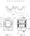
- the plastic bearing with the features of the invention consists of two half-shells 1 and 2, which are vulcanized in one piece or in one piece from an elastomeric material in a suitable mold in the position shown in FIG. 1.
- the sliding surface on the inside of the two half-shells has pockets 3 for receiving a lubricant.
- shell-shaped stiffening inserts 4 and 5 made of sheet metal, harder plastic or the like are provided.
- the two half-shells 1 and 2 are connected to one another by one or, if appropriate, by a plurality of webs 6.
- guide elements 7 and 8 are arranged on the two adjacent longitudinal edges of the half-shells 1 and 8 in the form of projections, which the half-shells when collapsed into the precise intermediate assembly position to lead.
- inclined surfaces 9 and 10 are formed on the projections, which come to rest against each other when the half-shells 1 and 2 are folded together and lead the half-shells on the last part of the folding movement into the exact intermediate assembly position, which can be seen particularly from FIG. 3.
- the pretensioning force can be changed, which has to be overcome during the pre-assembly of the plastic bearing and which holds the two shell halves together after folding into the position shown in FIG.
- This pretensioning force can thus be adapted to different circumstances and increased or decreased accordingly.
- One web 6 or a plurality of webs 6 can also be provided.
- Another variant consists in that on each of the guide elements 7 and 8 mutually opposite inclined surfaces 9 and 10 are formed in order to improve the safety of the snap-in movement achieved during the pre-assembly.
Landscapes
- Engineering & Computer Science (AREA)
- General Engineering & Computer Science (AREA)
- Mechanical Engineering (AREA)
- Manufacturing & Machinery (AREA)
- Vehicle Body Suspensions (AREA)
- Sliding-Contact Bearings (AREA)
- Bearings For Parts Moving Linearly (AREA)
- Support Of The Bearing (AREA)
Abstract
Description
- Die Erfindung bezieht sich auf ein Kunststofflager für Stabilisatoren in Kraftfahrzeugen nach dem Oberbegriff des Patentanspruches 1.
- Aus der DE-OS 42 04 252 ist ein solches Kunststofflager aus einem elastisch verformbaren Werkstoff bekannt, welches in einteiliger und für die Montage aufklappbarer Ausbildung in einer Achsebene geteilt ist, wobei ein Steg beide Halbschalen an einer Längskante miteinander verbindet. Im vormontierten Zustand weisen die Längskanten der beiden Halbschalen quer zur Teilungsebene einen Abstand voneinander auf, so daß die Halbschalen erst bei der Montage durch das Gehäuse zusammengedrückt werden und den Stabilisator dann unter gegenseitiger Berührung ihrer Längskanten zentriert rohrförmig umschließen.
- Ein solches Kunststofflager wird in der vormontierten Stellung der beiden Halbschalen in einer Form vulkanisiert, um bei der Montage den vorbestimmten und zentriert rohrförmigen Sitz der beiden Halbschalen auf dem Stabilisator zu erreichen. Erforderlich ist dazu ein relativ umfangreiches und kompliziertes Werkzeug.
- Aufgabe der Erfindung ist es daher, eine Ausbildung eines solchen Kunststofflagers zu schaffen, welches eine einfachere Herstellung in einem vereinfachten Werkzeug ohne Beeinträchtigung der Zuverlässigkeit eines genauen Sitzes des vormontierten Lagers auf dem Stabilisator ermöglicht.
- Zur Lösung dieser Aufgabe wird nach der Erfindung eine Ausbildung entsprechend dem Patentanspruch 1 vorgeschlagen.
- Diese Ausbildung ermöglicht eine Herstellung des Kunststofflagers in einteiliger Bauweise in einer um 180° gegeneinander aufgeklappten Lage und gewährleistet einen konzentriert rohrförmigen Sitz des Kunststofflagers auf dem Stabilisator nach der Montage. Die Herstellung des Kunststofflagers erfolgt also in einer aufgeklappten Stellung, in der die Teilungsebene beider Halbschalen etwa in einer gemeinsamen Hilfsebene liegt. Gegenüber herkömmlichen Kunststofflagern kann ein solches Kunststofflager in einem wesentlich vereinfachten Werkzeug ausvulkanisiert werden. Der Vorgang der Entformung nach dem Ausvulkanisieren und der Beschickung des Formwerkzeuges werden vereinfacht. Bei der Montage kommen die Führungselemente an den beiden Halbschalen in eine gegenseitige Berührung und sorgen auf dem letzten Weg der Zusammenführung beider Halbschalen für einen paßgenauen, zentriert rohrförmigen Sitz des Kunststofflagers auf dem Stabilisator. Vorzugsweise sind an den Führungselementen Schrägflächen ausgebildet, die den paßgenauen rohrförmigen Sitz beim Zusammenklappen der beiden Halbschalen zwangsläufig herbeiführen. Bei einer bevorzugten Ausbildung des Erfindungsgedankens sind die Schrägflächen an komplementären Vorsprüngen beider Halbschalen ausgebildet, wobei diese Vorsprünge beim Zusammenklappen der beiden Halbschalen sich gegenseitig behindern und nur unter elastischer Verformung der Stege in die dann durch Materialspannung fixierte Einbaulage verbringbar sind. Dadurch wird die Montage erleichtert und sichergestellt, daß das Kunststofflager bei der Montage sicher in die vorbestimmte Endlage gelangt und dann auch in dieser Endlage verbleibt. Außerdem sind falsch montierte Lager optisch leicht zu erkennen.
- Ein Ausführungsbeispiel der Erfindung ist in der Zeichnung dargestellt. Es zeigen:
- Figur 1
- eine Seitenansicht eines aufgeklappt dargestellten Kunststofflagers
- Figur 2
- einen Längsschnitt eines Kunststofflagers in einer Achsebene vor dem Einbau in ein das Kunststofflager umschließendes Gehäuse und
- Figur 3
- einen Querschnitt nach der Linie III - III in Figur 2.
- Das Kunststofflager mit den Erfindungsmerkmalen besteht aus zwei Halbschalen 1 und 2, die einteilig bzw. einstückig aus einem elastomeren Werkstoff in einem dazu geeigneten Formwerkzeug in der entsprechend Figur 1 aufgeklappten Stellung ausvulkanisiert sind. Die Gleitfläche an der Innenseite der beiden Halbschalen weist Taschen 3 zur Aufnahme eines Schmiermittels auf. Innerhalb des Werkstoffes beider Halbschalen 1 und 2 sind schalenförmige Versteifungseinlagen 4 und 5 aus Blech, härterem Kunststoff oder dergleichen vorgesehen. An einer Längskante sind beide Halbschalen 1 und 2 durch einen oder gegebenenfalls durch mehrere Stege 6 miteinander verbunden. Für die paßgenaue Zusammenführung der beiden Halbschalen 1 und 2 beim Zusammenklappen in eine Zwischenmontagestellung gemäß Figuren 2 und 3 sind an den beiden benachbarten Längskanten der Halbschalen 1 und 2 Führungselemente 7 und 8 in Form von Vorsprüngen angeordnet, die die Halbschalen beim Zusammenklappen in die präzise Zwischenmontagestellung führen. Dazu sind an den Vorsprüngen Schrägflächen 9 und 10 ausgebildet, die beim Zusammenklappen der Halbschalen 1 und 2 zur gegenseitigen Anlage kommen und die Halbschalen auf dem letzten Wegstück der Klappbewegung in die exakte Zwischenmontageposition führen, die besonders aus der Figur 3 erkennbar ist. Die beiden Halbschalen werden sodann durch das Gehäuse zusammengedrückt, bis die zuvor einander gegenüberliegenden Längskanten beider Halbschalen, und vor allem der Versteifungseinlagen, sich gegenseitig berühren und den Stabilisator rohrförmig konzentriert umschließen. Zur Fixierung der in den Figuren 2 und 3 dargestellten Zwischenmontageposition ist bei einer besonderen Ausbildung nach der Erfindung vorgesehen, daß die Schrägflächen an komplementären Vorsprüngen beider Halbschalen ausgebildet sind, die beim Gegeneinanderklappen der beiden Halbschalen sich gegenseitig behindern und nur unter elastischer Verformung des Steges 6 in die dann durch Materialspannung fixierte Zwischeneinbaulage verbringbar sind. Der Vorsprung 7 kann nur mit einem gedehnten Steg 6 über den Vorsprung 8 hinweggehoben werden, so daß die Materialspannung des Steges 6 die beiden Halbschalen in der Zwischenmontageposition gemäß Figuren 2 und 3 festhält. Erreicht wird dadurch gleichzeitig eine Erleichterung bei der optischen Überprüfung der richtigen Montageposition. Durch eine Veränderung des Querschnittes des Steges 6 läßt sich die Vorspannkraft verändern, die bei der Vormontage des Kunststofflagers zu überwinden ist und die die beiden Schalenhälften nach dem Zusammenklappen in die in Figur 2 dargestellte Position zusammenhält. Diese Vorspannkraft kann somit an unterschiedliche Gegebenheiten angepaßt und entsprechend vergrößert oder verkleinert werden. Es kann ein Steg 6 oder es können auch mehrere Stege 6 vorgesehen sein. Eine andere Variante besteht darin, daß an jedem der Führungselemente 7 und 8 beidseitig einander gegenüberliegende Schrägflächen 9 und 10 ausgebildet sind, um dadurch die Sicherheit der bei der Vormontage erreichten Einschnappbewegung zu verbessern. Abweichend von den zeichnerischen Darstellungen kann in der vormontierten Posistion auch nur einer der beiden Schlitze 11 oder 12 zwischen den einander gegenüberliegenden Kanten der beiden Schalenhälften offen und der andere Schlitz 11 oder 12 geschlossen sein, wodurch die Vorspannkraft in dem elastomeren Werkstoff bei der Einbaumontage in das Gehäuse beeinflußt werden kann.
-
- 1
- Halbschale
- 2
- Halbschale
- 3
- Vertiefung
- 4
- Versteifungseinlage
- 5
- Versteifungseinlage
- 6
- Steg
- 7
- Führungselement
- 8
- Führungselement
- 9
- Schrägfläche
- 10
- Schrägfläche
- 11
- Schlitz
- 12
- Schlitz
Claims (4)
- Kunststofflager für Stabilisatoren in Kraftfahrzeugen, bestehend aus zwei an einer Längsseite durch Stege einstückig miteinander verbundenen, aufklappbaren Halbschalen, deren Längsränder sich im montierten Zustand gegenseitig berühren, dadurch gekennzeichnet, daß die beiden Halbschalen (1,2) an der Seite ihrer Stegverbindung (6) je eines von zwei Führungselementen (7,8) aufweisen, die die Halbschalen (1,2) bei der Montage in die vorbestimmte Verschlußlage führen.
- Kunststofflager nach Anspruch 1, dadurch gekennzeichnet, daß an den Führungselementen (7,8) beider Halbschalen (1,2) Schrägflächen (9,10) ausgebildet sind.
- Kunststofflager nach den Ansprüchen 1 und 2, dadurch gekennzeichnet, daß die Schrägflächen (9,10) an komplementären Vorsprüngen (7,8) beider Halbschalen (1,2) ausgebildet sind und diese Vorsprünge beim Gegeneinanderklappen der beiden Halbschalen (1,2) sich gegenseitig behindern und nur unter elastischer Verformung des Steges (6) in die dann durch Materialspannung fixierte Einbaulage verbringbar sind.
- Kunststofflager nach den Ansprüchen 1 bis 3, dadurch gekennzeichnet, daß an jedem der Führungselemente (7,8) beidseitig einander gegenüberliegende Schrägflächen (9,10) ausgebildet sind.
Applications Claiming Priority (2)
| Application Number | Priority Date | Filing Date | Title |
|---|---|---|---|
| DE4413666 | 1994-04-20 | ||
| DE4413666A DE4413666C1 (de) | 1994-04-20 | 1994-04-20 | Kunststofflager für Stabilisatoren in Kraftfahrzeugen |
Publications (2)
| Publication Number | Publication Date |
|---|---|
| EP0678407A1 true EP0678407A1 (de) | 1995-10-25 |
| EP0678407B1 EP0678407B1 (de) | 1998-05-20 |
Family
ID=6515928
Family Applications (1)
| Application Number | Title | Priority Date | Filing Date |
|---|---|---|---|
| EP95104162A Expired - Lifetime EP0678407B1 (de) | 1994-04-20 | 1995-03-22 | Kunststofflager für Stabilisatoren in Kraftfahrzeugen |
Country Status (7)
| Country | Link |
|---|---|
| US (1) | US5520465A (de) |
| EP (1) | EP0678407B1 (de) |
| JP (1) | JP2620538B2 (de) |
| KR (1) | KR100188641B1 (de) |
| BR (1) | BR9501732A (de) |
| DE (2) | DE4413666C1 (de) |
| ES (1) | ES2117318T3 (de) |
Families Citing this family (28)
| Publication number | Priority date | Publication date | Assignee | Title |
|---|---|---|---|---|
| US6007058A (en) * | 1996-04-23 | 1999-12-28 | Tokai Rubber Industries, Ltd. | Mounting component for a cylindrical bushing and a mounting body |
| DE19709669C1 (de) * | 1997-03-11 | 1998-06-18 | Mannesmann Boge Gmbh | Gummilager, insbesondere für die Lagerung eines Stabilisatorstabes an einem Kraftfahrzeug |
| FR2766249A1 (fr) * | 1997-07-21 | 1999-01-22 | Caoutchouc Manuf Plastique | Palier elastique pour maintenir la barre de torsion d'un dispositif anti-devers |
| DE19746357C1 (de) * | 1997-10-21 | 1999-05-12 | Vorwerk & Sohn | Gummi/Metall-Lager zur Anlenkung eines Stabilisators an einem Kraftfahrzeugaufbau |
| US6170812B1 (en) | 1997-11-13 | 2001-01-09 | Btr Antivibration Systems, Inc. | Slipper bushing incorporating sealing and torque-reducing characteristics |
| JPH11210713A (ja) * | 1998-01-26 | 1999-08-03 | Orihashi Seisakusho:Kk | ずれ防止固定リング |
| ES2228034T3 (es) * | 1998-04-23 | 2005-04-01 | Nhk Spring Co. Ltd. | Dispositivo de retencion para un elemento de vastago. |
| RU2144152C1 (ru) * | 1999-07-15 | 2000-01-10 | Закрытое акционерное общество "Интеллект" | Подшипник скольжения слоистый |
| DE10006329C1 (de) * | 2000-02-12 | 2001-08-09 | Joern Gmbh | Gelenklager, insbesondere Stabilisatorlager für ein Fahrzeug |
| DE10049611C2 (de) | 2000-10-05 | 2002-08-29 | Zf Lemfoerder Metallwaren Ag | Gummilager mit Versteifungselement |
| DE10132379A1 (de) * | 2001-07-06 | 2003-01-16 | Zf Lemfoerder Metallwaren Ag | Gummilager, vorzugsweise Stabilisatorlager, und Verfahren zur Montage des Lagers |
| DE10144047A1 (de) * | 2001-09-07 | 2003-03-27 | Opel Adam Ag | Lager aus einem Elastomer mit Selbsthemmung |
| US6513801B1 (en) | 2002-07-24 | 2003-02-04 | The Pullman Company | Hinged/split reinforced clam shell bushing |
| US20040119330A1 (en) * | 2002-12-19 | 2004-06-24 | Wen-Hao Chuang | Non-metal hub |
| US6971640B2 (en) * | 2003-04-18 | 2005-12-06 | Research And Manufacturing Corporation Of America | Sway bar bushing |
| DE10354386B3 (de) * | 2003-11-20 | 2005-06-23 | Zf Friedrichshafen Ag | Gummilager zur Lagerung eines Profilstabes |
| FR2888166B1 (fr) * | 2005-07-08 | 2007-10-12 | Allevard Rejna Autosuspensions | Bague d'arret destinee a etre montee sur une barre stabilisatrice d'une suspension de vehicule automobile |
| KR101542956B1 (ko) * | 2011-07-29 | 2015-08-07 | 현대자동차 주식회사 | 자동차용 스태빌라이저 바의 마운트 부시 |
| KR101550598B1 (ko) * | 2011-07-29 | 2015-09-18 | 현대자동차 주식회사 | 자동차용 스태빌라이저 바의 마운트 부시 |
| WO2013121674A1 (ja) * | 2012-02-15 | 2013-08-22 | 本田技研工業株式会社 | ブッシュ |
| US9259812B1 (en) * | 2013-06-26 | 2016-02-16 | The Boeing Company | Clamp assembly and method |
| DE102014116755A1 (de) * | 2014-11-17 | 2016-05-19 | Dr. Ing. H.C. F. Porsche Aktiengesellschaft | Befestigungsvorrichtung |
| DE102015104864A1 (de) * | 2015-03-30 | 2016-10-06 | Thyssenkrupp Ag | Lagerelement für einen Stabilisator eines Fahrzeugs |
| US11035591B2 (en) * | 2015-10-13 | 2021-06-15 | Corosolar Llc | Bearing assembly for solar trackers |
| KR101766111B1 (ko) * | 2016-01-19 | 2017-08-07 | 현대자동차주식회사 | 내부 구성요소의 회전이 가능한 부시와 이를 구비한 스태빌라이저 바 어셈블리 |
| CN108463647B (zh) * | 2016-12-15 | 2020-06-02 | 住友理工株式会社 | 筒形防振装置 |
| DE102018113503A1 (de) * | 2018-06-06 | 2019-12-12 | Vibracoustic Gmbh | Aggregatelager |
| KR102714870B1 (ko) * | 2019-07-19 | 2024-10-08 | 현대자동차주식회사 | 튜닝 자유도 개선형 부시 및 현가 시스템 |
Citations (7)
| Publication number | Priority date | Publication date | Assignee | Title |
|---|---|---|---|---|
| JPS5751036A (en) * | 1980-09-11 | 1982-03-25 | Toyota Motor Corp | Cylindrical bush assembly |
| JPH0272220A (ja) * | 1988-09-02 | 1990-03-12 | Koyo Seiko Co Ltd | 二つ割り外輪の割り方法 |
| EP0381566A1 (de) * | 1989-01-31 | 1990-08-08 | Hutchinson | Drehstablager |
| EP0381945A2 (de) * | 1989-02-04 | 1990-08-16 | Jörn GmbH | Gummmi-Metall-Buchse, insbesondere für die Lagerung eines Stabilisatorstabes an einem Kraftfahrzeug |
| FR2657564A1 (fr) * | 1990-02-01 | 1991-08-02 | Peugeot | Palier elastique a glissement interne. |
| JPH04349012A (ja) * | 1991-05-24 | 1992-12-03 | Nippon Mektron Ltd | スタビライザの支持ブッシュ |
| DE4204252A1 (de) * | 1992-02-13 | 1993-08-19 | Lemfoerder Metallwaren Ag | Kunststofflager fuer stabilisatoren in kraftfahrzeugen |
Family Cites Families (4)
| Publication number | Priority date | Publication date | Assignee | Title |
|---|---|---|---|---|
| US3194615A (en) * | 1962-07-03 | 1965-07-13 | Anthony V Weasler | Shaft organization |
| US3820860A (en) * | 1972-08-03 | 1974-06-28 | Stone Conveyor Inc | Variable bore clearance bearing |
| US5072821A (en) * | 1990-12-07 | 1991-12-17 | Otis Elevator Company | Escalator/people mover bearing |
| DE4312958A1 (de) * | 1993-04-21 | 1994-10-27 | Lemfoerder Metallwaren Ag | Kunststofflager für Stabilisatoren in Kraftfahrzeugen |
-
1994
- 1994-04-20 DE DE4413666A patent/DE4413666C1/de not_active Expired - Fee Related
-
1995
- 1995-03-16 KR KR1019950005396A patent/KR100188641B1/ko not_active Expired - Fee Related
- 1995-03-22 ES ES95104162T patent/ES2117318T3/es not_active Expired - Lifetime
- 1995-03-22 EP EP95104162A patent/EP0678407B1/de not_active Expired - Lifetime
- 1995-03-22 DE DE59502217T patent/DE59502217D1/de not_active Expired - Fee Related
- 1995-04-06 US US08/431,255 patent/US5520465A/en not_active Expired - Lifetime
- 1995-04-19 BR BR9501732A patent/BR9501732A/pt not_active IP Right Cessation
- 1995-04-19 JP JP7094028A patent/JP2620538B2/ja not_active Expired - Fee Related
Patent Citations (7)
| Publication number | Priority date | Publication date | Assignee | Title |
|---|---|---|---|---|
| JPS5751036A (en) * | 1980-09-11 | 1982-03-25 | Toyota Motor Corp | Cylindrical bush assembly |
| JPH0272220A (ja) * | 1988-09-02 | 1990-03-12 | Koyo Seiko Co Ltd | 二つ割り外輪の割り方法 |
| EP0381566A1 (de) * | 1989-01-31 | 1990-08-08 | Hutchinson | Drehstablager |
| EP0381945A2 (de) * | 1989-02-04 | 1990-08-16 | Jörn GmbH | Gummmi-Metall-Buchse, insbesondere für die Lagerung eines Stabilisatorstabes an einem Kraftfahrzeug |
| FR2657564A1 (fr) * | 1990-02-01 | 1991-08-02 | Peugeot | Palier elastique a glissement interne. |
| JPH04349012A (ja) * | 1991-05-24 | 1992-12-03 | Nippon Mektron Ltd | スタビライザの支持ブッシュ |
| DE4204252A1 (de) * | 1992-02-13 | 1993-08-19 | Lemfoerder Metallwaren Ag | Kunststofflager fuer stabilisatoren in kraftfahrzeugen |
Non-Patent Citations (3)
| Title |
|---|
| PATENT ABSTRACTS OF JAPAN vol. 006, no. 124 (M - 141) 9 July 1982 (1982-07-09) * |
| PATENT ABSTRACTS OF JAPAN vol. 014, no. 256 (M - 0980) 4 June 1990 (1990-06-04) * |
| PATENT ABSTRACTS OF JAPAN vol. 017, no. 208 (M - 1401) 23 April 1993 (1993-04-23) * |
Also Published As
| Publication number | Publication date |
|---|---|
| KR100188641B1 (en) | 1999-06-01 |
| DE59502217D1 (de) | 1998-06-25 |
| EP0678407B1 (de) | 1998-05-20 |
| DE4413666C1 (de) | 1995-06-14 |
| JP2620538B2 (ja) | 1997-06-18 |
| ES2117318T3 (es) | 1998-08-01 |
| US5520465A (en) | 1996-05-28 |
| BR9501732A (pt) | 1995-11-14 |
| JPH07301230A (ja) | 1995-11-14 |
Similar Documents
| Publication | Publication Date | Title |
|---|---|---|
| EP0678407A1 (de) | Kunststofflager für Stabilisatoren in Kraftfahrzeugen | |
| EP0618096B1 (de) | Gummilager für den Mittelzapfen einer Blattfederaufhängung in einem Kraftfahrzeug | |
| DE102004052604B3 (de) | Kopfstützenhülse | |
| DE3840176C2 (de) | ||
| DE2655353A1 (de) | Elastische verbindung eines axialgelenks mit dem anschlussgestaenge einer kraftfahrzeuglenkung | |
| DE2337309A1 (de) | Radiallager | |
| DE102009032855A1 (de) | Stirnwandoberteilstruktur eines Fahrzeugs | |
| DE4204252C2 (de) | Kunststofflager für Stabilisatoren in Kraftfahrzeugen | |
| DE112016005943B4 (de) | Röhrenförmige Schwingungsdämpfungsvorrichtung | |
| DE2937083B1 (de) | Radblende,insbesondere fuer die Raeder von Personenkraftwagen | |
| DE10190280B4 (de) | Lenkvorrichtung mit Verlängerbaren Wellen | |
| DE10231014B4 (de) | Pendelstütze mit integriertem Kugelgelenk | |
| DE69813676T2 (de) | Kraftfahrzeug Scheibenwischervorrichtung mit vereinfachten Mitteln zur Montage | |
| US6854765B2 (en) | Steering shaft assembly | |
| EP0462450A1 (de) | Abschlussteil für Kraftfahrzeug | |
| DE2814009A1 (de) | Kunststoff-hammerbuerstenhalter | |
| DE3221293A1 (de) | Stossfaenger fuer kraftfahrzeuge, insbesondere fuer einen personenkraftwagen | |
| DE4334776C5 (de) | Linearführungsvorrichtung mit Gleitdichtung | |
| DE2630656A1 (de) | Kugellager-ausruecker, insbesondere fuer kraftfahrzeugkupplungen | |
| DE10060229A1 (de) | Verschiebeanordnung für eine Gelenkwelle | |
| DE4420487C1 (de) | Hohlzapfengelenk | |
| DE10247757B3 (de) | Drehmomentstütze, insbesondere zum Abstützen des Motors an der Karosserie eines Kraftfahrzeugs | |
| DE19537206C2 (de) | Stoßdämpfer | |
| DE4127381C2 (de) | Deformationselement, insbesondere für ein Kraftfahrzeug | |
| DE3307008C2 (de) |
Legal Events
| Date | Code | Title | Description |
|---|---|---|---|
| PUAI | Public reference made under article 153(3) epc to a published international application that has entered the european phase |
Free format text: ORIGINAL CODE: 0009012 |
|
| AK | Designated contracting states |
Kind code of ref document: A1 Designated state(s): DE ES FR GB IT SE |
|
| 17P | Request for examination filed |
Effective date: 19951020 |
|
| 17Q | First examination report despatched |
Effective date: 19961018 |
|
| GRAG | Despatch of communication of intention to grant |
Free format text: ORIGINAL CODE: EPIDOS AGRA |
|
| GRAG | Despatch of communication of intention to grant |
Free format text: ORIGINAL CODE: EPIDOS AGRA |
|
| GRAH | Despatch of communication of intention to grant a patent |
Free format text: ORIGINAL CODE: EPIDOS IGRA |
|
| GRAH | Despatch of communication of intention to grant a patent |
Free format text: ORIGINAL CODE: EPIDOS IGRA |
|
| GRAA | (expected) grant |
Free format text: ORIGINAL CODE: 0009210 |
|
| AK | Designated contracting states |
Kind code of ref document: B1 Designated state(s): DE ES FR GB IT SE |
|
| GBT | Gb: translation of ep patent filed (gb section 77(6)(a)/1977) |
Effective date: 19980526 |
|
| REF | Corresponds to: |
Ref document number: 59502217 Country of ref document: DE Date of ref document: 19980625 |
|
| ET | Fr: translation filed | ||
| ITF | It: translation for a ep patent filed | ||
| REG | Reference to a national code |
Ref country code: ES Ref legal event code: FG2A Ref document number: 2117318 Country of ref document: ES Kind code of ref document: T3 |
|
| PLBE | No opposition filed within time limit |
Free format text: ORIGINAL CODE: 0009261 |
|
| STAA | Information on the status of an ep patent application or granted ep patent |
Free format text: STATUS: NO OPPOSITION FILED WITHIN TIME LIMIT |
|
| 26N | No opposition filed | ||
| REG | Reference to a national code |
Ref country code: GB Ref legal event code: IF02 |
|
| PGFP | Annual fee paid to national office [announced via postgrant information from national office to epo] |
Ref country code: GB Payment date: 20060322 Year of fee payment: 12 |
|
| PGFP | Annual fee paid to national office [announced via postgrant information from national office to epo] |
Ref country code: IT Payment date: 20060331 Year of fee payment: 12 |
|
| PGFP | Annual fee paid to national office [announced via postgrant information from national office to epo] |
Ref country code: ES Payment date: 20060425 Year of fee payment: 12 |
|
| PGFP | Annual fee paid to national office [announced via postgrant information from national office to epo] |
Ref country code: SE Payment date: 20070307 Year of fee payment: 13 |
|
| PGFP | Annual fee paid to national office [announced via postgrant information from national office to epo] |
Ref country code: DE Payment date: 20070315 Year of fee payment: 13 |
|
| GBPC | Gb: european patent ceased through non-payment of renewal fee |
Effective date: 20070322 |
|
| PG25 | Lapsed in a contracting state [announced via postgrant information from national office to epo] |
Ref country code: GB Free format text: LAPSE BECAUSE OF NON-PAYMENT OF DUE FEES Effective date: 20070322 |
|
| PGFP | Annual fee paid to national office [announced via postgrant information from national office to epo] |
Ref country code: FR Payment date: 20070308 Year of fee payment: 13 |
|
| REG | Reference to a national code |
Ref country code: ES Ref legal event code: FD2A Effective date: 20070323 |
|
| PG25 | Lapsed in a contracting state [announced via postgrant information from national office to epo] |
Ref country code: ES Free format text: LAPSE BECAUSE OF NON-PAYMENT OF DUE FEES Effective date: 20070323 |
|
| EUG | Se: european patent has lapsed | ||
| REG | Reference to a national code |
Ref country code: FR Ref legal event code: ST Effective date: 20081125 |
|
| PG25 | Lapsed in a contracting state [announced via postgrant information from national office to epo] |
Ref country code: SE Free format text: LAPSE BECAUSE OF NON-PAYMENT OF DUE FEES Effective date: 20080323 Ref country code: DE Free format text: LAPSE BECAUSE OF NON-PAYMENT OF DUE FEES Effective date: 20081001 |
|
| PG25 | Lapsed in a contracting state [announced via postgrant information from national office to epo] |
Ref country code: FR Free format text: LAPSE BECAUSE OF NON-PAYMENT OF DUE FEES Effective date: 20080331 |
|
| PG25 | Lapsed in a contracting state [announced via postgrant information from national office to epo] |
Ref country code: IT Free format text: LAPSE BECAUSE OF NON-PAYMENT OF DUE FEES Effective date: 20070322 |