EP0678435A1 - Train de roulement pour véhicules ferroviaires - Google Patents
Train de roulement pour véhicules ferroviaires Download PDFInfo
- Publication number
- EP0678435A1 EP0678435A1 EP95105232A EP95105232A EP0678435A1 EP 0678435 A1 EP0678435 A1 EP 0678435A1 EP 95105232 A EP95105232 A EP 95105232A EP 95105232 A EP95105232 A EP 95105232A EP 0678435 A1 EP0678435 A1 EP 0678435A1
- Authority
- EP
- European Patent Office
- Prior art keywords
- idler wheels
- idler
- chassis
- steering
- coupling
- Prior art date
- Legal status (The legal status is an assumption and is not a legal conclusion. Google has not performed a legal analysis and makes no representation as to the accuracy of the status listed.)
- Granted
Links
- 238000010168 coupling process Methods 0.000 claims abstract description 25
- 238000005859 coupling reaction Methods 0.000 claims abstract description 25
- 230000008878 coupling Effects 0.000 claims description 24
- 230000000694 effects Effects 0.000 description 2
- 238000000034 method Methods 0.000 description 2
- 230000003068 static effect Effects 0.000 description 2
- 230000003247 decreasing effect Effects 0.000 description 1
- 238000011161 development Methods 0.000 description 1
- 230000018109 developmental process Effects 0.000 description 1
- 238000006073 displacement reaction Methods 0.000 description 1
- 238000005516 engineering process Methods 0.000 description 1
- 230000002349 favourable effect Effects 0.000 description 1
- 239000013641 positive control Substances 0.000 description 1
- 230000000717 retained effect Effects 0.000 description 1
- 230000033764 rhythmic process Effects 0.000 description 1
Images


Classifications
-
- B—PERFORMING OPERATIONS; TRANSPORTING
- B61—RAILWAYS
- B61F—RAIL VEHICLE SUSPENSIONS, e.g. UNDERFRAMES, BOGIES OR ARRANGEMENTS OF WHEEL AXLES; RAIL VEHICLES FOR USE ON TRACKS OF DIFFERENT WIDTH; PREVENTING DERAILING OF RAIL VEHICLES; WHEEL GUARDS, OBSTRUCTION REMOVERS OR THE LIKE FOR RAIL VEHICLES
- B61F3/00—Types of bogies
- B61F3/16—Types of bogies with a separate axle for each wheel
-
- B—PERFORMING OPERATIONS; TRANSPORTING
- B61—RAILWAYS
- B61F—RAIL VEHICLE SUSPENSIONS, e.g. UNDERFRAMES, BOGIES OR ARRANGEMENTS OF WHEEL AXLES; RAIL VEHICLES FOR USE ON TRACKS OF DIFFERENT WIDTH; PREVENTING DERAILING OF RAIL VEHICLES; WHEEL GUARDS, OBSTRUCTION REMOVERS OR THE LIKE FOR RAIL VEHICLES
- B61F5/00—Constructional details of bogies; Connections between bogies and vehicle underframes; Arrangements or devices for adjusting or allowing self-adjustment of wheel axles or bogies when rounding curves
- B61F5/38—Arrangements or devices for adjusting or allowing self- adjustment of wheel axles or bogies when rounding curves, e.g. sliding axles, swinging axles
Definitions
- the invention relates to a chassis for rail vehicles, in particular low-floor light rail vehicles, with four idler gears, of which the two idler gears arranged in a transverse plane of the chassis each form a pair of idler gears without coupling the rotary movement of these idler gears.
- a torsionally rigid wheel set shaft that is to say also coupled in terms of their speed.
- Such a wheel set has the property of automatically controlling itself in the track channel along a sine-like line, i. that is, the wheelset always strives to run in the middle of the track channel.
- the wheel flange remains largely free of executives, at least in the straight line and in curves with a large radius.
- wheels that are not tangential to the rail must be moved across the rail in the direction of travel. This so-called turning movement takes place with the participation of the flanges against the effect of the coefficient of friction between the wheel and the rail.
- the coefficient of static friction is reduced due to the presence of the longitudinal slippage.
- EP-A-0 511 949 discloses a method for controlling a chassis without rigid axle connections, in which at least two opposite idler wheels are individually driven by separately controllable electric motors.
- the power of the electric motors of opposing wheels is periodically increased or decreased within predetermined ranges, the power change being in phase opposition he follows.
- Special control devices are required to generate such an artificial clock-push-pull rhythm.
- DE-C-38 08 593 describes a motor bogie with idler gears, of which two idler gears opposite one another in the transverse direction are connected in a torsionally rigid manner by means of gears. This should largely maintain the guiding properties of a wheelset with a continuous wheelset shaft.
- the gear means used as a replacement for the wheelset shaft are subject to extremely high loads, especially when driving through narrow bends.
- the prior art also includes a driven undercarriage with steerable individual drives with positive control (EP-B-0 439 574).
- the articulation angle of articulated car bodies is transmitted to the individual drives for their radial radial adjustment via a steering linkage.
- Such a forced control always means a higher structural effort, the desired radial curve setting of the drives when entering and exiting the articulated trolley into or out of a track curve cannot be exactly present.
- the invention has for its object to give the idler gears of a carriage of the generic type the property of the automatic tangential attitude to the rail, which property should consist both in the straight line and in any track curve.
- the idler wheels arranged one behind the other in the longitudinal direction of the undercarriage are coupled in terms of their speed, the idler wheels being able to pivot to any other vehicle parts independently of the position of the undercarriage about any vertical pivot axis arranged within their track width, and the idler wheels are coupled in their swiveling or steering movements.
- a running gear with the above-mentioned features can advantageously assume a position in the track channel automatically in all situations, which enables the idler wheels to roll without longitudinal and transverse slip without a contact angle to the rail.
- the coupling of the steering movements of the idler gears takes place according to a preferred embodiment of the invention such that the steering angle of the idler gears arranged one behind the other is always of the same magnitude, but in the opposite direction, while the steering angle of the idler wheels each assigned to a transverse plane of the chassis are the same or differ only by the amount that is useful for compensating for the difference in radius between the outer rail and the inner rail.
- positive-locking connection means are provided for the speed coupling of the idler wheels arranged one behind the other, which include length compensation corresponding to the steering movements of the idler wheels.
- Chains or toothed belts with associated gear wheels attached to the respective idler gear are conceivable as form-fitting connecting means.
- the connecting means are each formed from at least two angular gears and a coupling shaft which is variable in length.
- An angular gear of each chassis longitudinal side can be connected to the drive shaft of a traction motor, which, for. B. is arranged on or in the body of the rail vehicle.
- a next embodiment of the invention consists in that the connecting means each have two angular gears, a longitudinal drive motor connected to them, and a compensating clutch arranged between the respective angular gear and the idler wheel.
- the idler wheels are cushioned by primary springs, the springs permitting movements of the idler wheels corresponding to their elasticity not only in the vertical direction but also in the transverse direction and especially for the steering movements of the idler wheels in the longitudinal direction.
- the vertical spring movements of the idler wheels can be compensated for by the same compensating clutches that allow the steering movements of the idler wheels to each other.
- a further, favorable embodiment of the invention consists in the fact that the swivel axes of the idler gears are designed virtually.
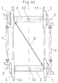
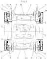
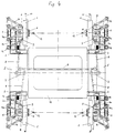
- FIG. 1a, 1b, 2, 3 and 4 each show the principle of a coupling wheel undercarriage in a top view.
- the undercarriage has a total of four idler wheels 1, which are rotatably mounted in pairs on an axle bridge 2 each.
- the non-rotating axle bridges 2 can be cranked in the direction of the level of the rails 11 in order to enable a low-floor light rail car with a low-lying floor in the area of the running gear.
- the speed of the idler wheels 1, which are arranged one behind the other in the longitudinal direction of the running gear, are coupled in terms of their speed by form-fitting connecting means. According to FIGS. 1a and 1b, this coupling takes place via an angular gear 3 connected to each idler gear 1 and a coupling shaft 4 in each case. According to FIG. 2, the idler gears 1 are on each chassis side With the help of a traction motor 5 and the angular gear 3 coupled in the embodiment with further spur gears 3a in their speed and of course driven.
- the two pairs of wheels formed from idler gears 1 of a chassis transverse plane are coupled with one another in their steering movements about vertical pivot axes 12 arranged in the longitudinal center axis of the chassis such that the steering angles of these wheel pairs are always of the same magnitude, but in the opposite direction.
- the steering coupling of the idler gear pairs takes place, for example, through the handlebar 8 shown in FIG. 1b or through the lever 7 and handlebar 8 shown in FIG. 1a and FIG. 2.
- the pivot axes 12 can be physically designed (FIGS. 1a and 1b) or as virtual ones Axes exist (Fig. 2).
- each idler gear 1 and the gear means are telescopically variable in length, for. B. by integrated gears.
- compensating clutches 6 arranged between each idler gear 1 and the gear means enable said steering movements.
- the steering angle is on the order of 2 ° (with one pair of idler gear + 2 °, with the other - 2 °).
- the axle bridges 2 can be cushioned against a chassis frame 10 via primary springs 9.
- the springs 9 - preferably flexicoil springs - should also allow spring movements of the respective axle bridge 2 in the longitudinal direction corresponding to their elasticity, in order to enable the desired steering movement of the idler gear pairs.
- the steering coupling of the two wheel pairs shown in FIG. 2 as an example also allows a transverse elastic wheel pair guidance via these primary springs 9 in the chassis frame 10, without transverse movements of the wheel pairs influencing the steering coupling.
- the compensating clutches 6 compensate for all spring movements of the axle bridges 2 in relation to the chassis frame 10 and any spring movements of the motor-gear units (parts 5 and 3 or 3a), which in turn can be suspended elastically on the chassis frame 10.
- each idler wheel 1 is a separate one within the track width assigned pivot axis 12 assigned.
- the advantage of these separate swivel axes 12 is that, with comparable swivel angles, smaller longitudinal displacement paths of the idler gears 1 compared to the gear means 3 and 3a occur, and the design of the compensating clutches 6 is thereby simplified.
- the idler gears 1 are each rotatably mounted on a steering knuckle 13.
- the steering knuckles 13 of the idler wheels 1 assigned to a transverse plane of the chassis are in turn each fastened to an axle bridge 2 so as to be steerable about the pivot axes 12.
- the axle bridges 2 cannot be pivoted relative to the chassis frame 10; the steering movements are carried out only by the idler wheels 1 and the associated steering knuckles 13, the steering movements of which are in turn coupled via the handlebars 8 and levers 7.
- each idler gear 1 is individually virtual. This is done with the aid of lower wheel links 14, the intersection of the elongated longitudinal axes of the two lower wheel links 14 assigned to an idler gear 1 representing the virtual pivot axis 12.
- the lower wheel control arms 14 take over together with upper wheel links 14a, the transverse guidance of the idler gears 1.
- the idler gears 1 are supported vertically by primary springs 9, specifically in this exemplary embodiment with respect to the drive block formed by the drive motor 5 and the gear means. This drive block thus fulfills the load-bearing function of a longitudinal member of the undercarriage, so that the remaining undercarriage frame 10 can be designed very simply and essentially only has the task of maintaining the track dimension.
- the steering coupling of the idler wheels 1 is also carried out in the example of FIG. 4 by the handlebars 8 and levers 7.
- the handlebars 8 and levers 7 By appropriately arranging the points of engagement of the links 8 on the levers 7, either the same steering angle or according to a desired one can be easily achieved for the idler wheels 1 of a transverse chassis plane Compensation of the difference in radii between the outer rail and the inner rail slightly different steering angles can be achieved.
- This opposite change in the wheelbase on the left and right side of the chassis is synonymous with a pivoting movement of the idler wheels 1 about their respective pivot axis 12.
- the steering angle of the idler wheels 1 is therefore corrected as long as the wheels running one behind the other do not roll on the same diameter.
- the system therefore always endeavors to correct incorrect steering angles, which result in the change in the position of the wheel contact points and thus in the change in the effective wheel diameter.
- this system will drive without a wrong steering angle. If you drive without a wrong steering angle, the centering property of an idler gear, even if it is only slight, can ultimately have an effect.
Landscapes
- Engineering & Computer Science (AREA)
- Mechanical Engineering (AREA)
- Automatic Cycles, And Cycles In General (AREA)
- Handcart (AREA)
- Fittings On The Vehicle Exterior For Carrying Loads, And Devices For Holding Or Mounting Articles (AREA)
- Steering-Linkage Mechanisms And Four-Wheel Steering (AREA)
Applications Claiming Priority (2)
| Application Number | Priority Date | Filing Date | Title |
|---|---|---|---|
| DE4414293 | 1994-04-23 | ||
| DE4414293A DE4414293C1 (de) | 1994-04-23 | 1994-04-23 | Fahrwerk für Schienenfahrzeuge |
Publications (2)
| Publication Number | Publication Date |
|---|---|
| EP0678435A1 true EP0678435A1 (fr) | 1995-10-25 |
| EP0678435B1 EP0678435B1 (fr) | 1998-06-24 |
Family
ID=6516314
Family Applications (1)
| Application Number | Title | Priority Date | Filing Date |
|---|---|---|---|
| EP95105232A Expired - Lifetime EP0678435B1 (fr) | 1994-04-23 | 1995-04-07 | Train de roulement pour véhicules ferroviaires |
Country Status (4)
| Country | Link |
|---|---|
| EP (1) | EP0678435B1 (fr) |
| AT (1) | ATE167649T1 (fr) |
| DE (2) | DE4414293C1 (fr) |
| ES (1) | ES2117321T3 (fr) |
Cited By (3)
| Publication number | Priority date | Publication date | Assignee | Title |
|---|---|---|---|---|
| FR2826328A1 (fr) * | 2001-06-26 | 2002-12-27 | Alstom | Bogie moteur pour vehicule ferroviaire a plancher bas integral |
| CN108657213A (zh) * | 2017-03-30 | 2018-10-16 | 比亚迪股份有限公司 | 转向架及具有其的轨道车辆和轨道交通系统 |
| CN114407958A (zh) * | 2020-10-28 | 2022-04-29 | 湖南中车智行科技有限公司 | 一种用于铰接式汽车列车的胶轮导向转向架装置 |
Citations (8)
| Publication number | Priority date | Publication date | Assignee | Title |
|---|---|---|---|---|
| FR680756A (fr) * | 1928-08-24 | 1930-05-06 | Cie J G Brill | Perfectionnements aux voitures de chemins de fer |
| FR1014449A (fr) * | 1950-03-14 | 1952-08-14 | Bogie à roues indépendantes pour véhicules sur rails | |
| FR2511962A1 (fr) * | 1981-08-31 | 1983-03-04 | South African Inventions | Train de roues pour vehicule ferroviaire stabilise |
| GB2202813A (en) * | 1987-03-31 | 1988-10-05 | Krauss Maffei Ag | Track vehicle |
| DE3808593A1 (de) * | 1988-03-15 | 1989-09-28 | Gutehoffnungshuette Man | Radsatzfuehrung fuer drehgestelle von schienenfahrzeugen, insbesondere fahrzeuge des nahverkehrs |
| EP0369241A2 (fr) * | 1988-11-17 | 1990-05-23 | Bergische Stahl-Industrie | Suspension spatiale de roues individuelles de véhicules ferroviaires |
| WO1991002673A1 (fr) * | 1989-08-21 | 1991-03-07 | Sig Schweizerische Industrie-Gesellschaft | Chassis entraine a appareils de roulement individuels man×uvrables |
| EP0511949A2 (fr) * | 1991-04-30 | 1992-11-04 | SGP Verkehrstechnik Gesellschaft m.b.H. | Procédé de commande d'un train de roues sans liaison par essieu rigide |
Family Cites Families (1)
| Publication number | Priority date | Publication date | Assignee | Title |
|---|---|---|---|---|
| DE3478852D1 (en) * | 1983-11-28 | 1989-08-10 | Duewag Ag | Double drive for rail vehicles |
-
1994
- 1994-04-23 DE DE4414293A patent/DE4414293C1/de not_active Expired - Fee Related
-
1995
- 1995-04-07 AT AT95105232T patent/ATE167649T1/de not_active IP Right Cessation
- 1995-04-07 ES ES95105232T patent/ES2117321T3/es not_active Expired - Lifetime
- 1995-04-07 EP EP95105232A patent/EP0678435B1/fr not_active Expired - Lifetime
- 1995-04-07 DE DE59502630T patent/DE59502630D1/de not_active Expired - Fee Related
Patent Citations (9)
| Publication number | Priority date | Publication date | Assignee | Title |
|---|---|---|---|---|
| FR680756A (fr) * | 1928-08-24 | 1930-05-06 | Cie J G Brill | Perfectionnements aux voitures de chemins de fer |
| FR1014449A (fr) * | 1950-03-14 | 1952-08-14 | Bogie à roues indépendantes pour véhicules sur rails | |
| FR2511962A1 (fr) * | 1981-08-31 | 1983-03-04 | South African Inventions | Train de roues pour vehicule ferroviaire stabilise |
| GB2202813A (en) * | 1987-03-31 | 1988-10-05 | Krauss Maffei Ag | Track vehicle |
| DE3808593A1 (de) * | 1988-03-15 | 1989-09-28 | Gutehoffnungshuette Man | Radsatzfuehrung fuer drehgestelle von schienenfahrzeugen, insbesondere fahrzeuge des nahverkehrs |
| EP0369241A2 (fr) * | 1988-11-17 | 1990-05-23 | Bergische Stahl-Industrie | Suspension spatiale de roues individuelles de véhicules ferroviaires |
| WO1991002673A1 (fr) * | 1989-08-21 | 1991-03-07 | Sig Schweizerische Industrie-Gesellschaft | Chassis entraine a appareils de roulement individuels man×uvrables |
| EP0439574A1 (fr) * | 1989-08-21 | 1991-08-07 | Sig Schweiz Industrieges | Chassis entraine a appareils de roulement individuels man uvrables. |
| EP0511949A2 (fr) * | 1991-04-30 | 1992-11-04 | SGP Verkehrstechnik Gesellschaft m.b.H. | Procédé de commande d'un train de roues sans liaison par essieu rigide |
Cited By (7)
| Publication number | Priority date | Publication date | Assignee | Title |
|---|---|---|---|---|
| FR2826328A1 (fr) * | 2001-06-26 | 2002-12-27 | Alstom | Bogie moteur pour vehicule ferroviaire a plancher bas integral |
| EP1270359A1 (fr) * | 2001-06-26 | 2003-01-02 | Alstom | Bogie moteur pour vehicule ferroviaire a plancher bas integral |
| US6601520B2 (en) | 2001-06-26 | 2003-08-05 | Alstom | Motor bogie for a vehicle having an integral low-slung floor |
| AU779297B2 (en) * | 2001-06-26 | 2005-01-13 | Alstom Transport Technologies | A motor bogie for a vehicle having an integral low-slung floor |
| CN108657213A (zh) * | 2017-03-30 | 2018-10-16 | 比亚迪股份有限公司 | 转向架及具有其的轨道车辆和轨道交通系统 |
| CN108657213B (zh) * | 2017-03-30 | 2020-04-24 | 比亚迪股份有限公司 | 转向架及具有其的轨道车辆和轨道交通系统 |
| CN114407958A (zh) * | 2020-10-28 | 2022-04-29 | 湖南中车智行科技有限公司 | 一种用于铰接式汽车列车的胶轮导向转向架装置 |
Also Published As
| Publication number | Publication date |
|---|---|
| EP0678435B1 (fr) | 1998-06-24 |
| ES2117321T3 (es) | 1998-08-01 |
| ATE167649T1 (de) | 1998-07-15 |
| DE59502630D1 (de) | 1998-07-30 |
| DE4414293C1 (de) | 1995-09-14 |
Similar Documents
| Publication | Publication Date | Title |
|---|---|---|
| DE69428683T2 (de) | Sich selbsttätig einstellendes drehgestell | |
| CH676220A5 (fr) | ||
| DE19538379C1 (de) | Zweirädiges Fahrwerk für spurgeführte Fahrzeuge | |
| DE3827412C2 (fr) | ||
| DE19826448C2 (de) | Fahrwerk für ein Schienenfahrzeug | |
| DE102017003528B4 (de) | Fahrzeug mit hoher Manövrierbarkeit und vier unabhängig voneinander antreibbaren Antriebsrädern | |
| EP0308616B1 (fr) | Groupe de propulsion pour véhicules ferroviaires | |
| EP0649782B1 (fr) | Véhicule ferroviaire et train de roulement pour un tel véhicule | |
| EP3272614A1 (fr) | Train de roulement pour un véhicule sur rail | |
| EP0135877A2 (fr) | Train de roulement pour véhicules ferroviaires | |
| EP0168578B1 (fr) | Train de roues pour véhicules ferroviaires | |
| EP0678435B1 (fr) | Train de roulement pour véhicules ferroviaires | |
| EP0630797B1 (fr) | Véhicule ferroviaire à plancher bas | |
| EP0580995A1 (fr) | Système de véhicules guidés consistant d'au moins deux véhicules avec des trains de roulement commandés avec des trains de roues uniques | |
| EP0410407B1 (fr) | Sous-châssis de roulement pour un véhicule ou un bogie ferroviaires | |
| EP2939898B1 (fr) | Boggie pour véhicules sur rails ayant trois essieux montés | |
| EP0855326A2 (fr) | Train de roulement avec deux essieux pour système de transport sur rails. | |
| DE9406843U1 (de) | Fahrwerk für Schienenfahrzeuge | |
| WO1999046155A1 (fr) | Dispositif pour transmettre les forces longitudinales d'un bati tournant sur la caisse d'un vehicule sur rails, notamment d'un vehicule moteur a force de traction elevee | |
| CH671929A5 (fr) | ||
| DE9409044U1 (de) | Niederflur-Gelenktriebwagen, insbesondere für den Personenverkehr auf innerstädtischen Schienennetzen | |
| EP0444015B1 (fr) | Guidage d'essieux pour bogies ferroviaires | |
| EP0679561A1 (fr) | Bogie auto-directeur à trois essieux avec poutres de direction | |
| EP4091903A1 (fr) | Châssis et véhicule ferroviaire | |
| EP0444017B1 (fr) | Guidage d'essieux pour véhicules sur rail |
Legal Events
| Date | Code | Title | Description |
|---|---|---|---|
| PUAI | Public reference made under article 153(3) epc to a published international application that has entered the european phase |
Free format text: ORIGINAL CODE: 0009012 |
|
| AK | Designated contracting states |
Kind code of ref document: A1 Designated state(s): AT BE CH DE DK ES FR GB GR IE IT LI NL PT SE |
|
| 17P | Request for examination filed |
Effective date: 19951215 |
|
| 17Q | First examination report despatched |
Effective date: 19961031 |
|
| GRAG | Despatch of communication of intention to grant |
Free format text: ORIGINAL CODE: EPIDOS AGRA |
|
| GRAG | Despatch of communication of intention to grant |
Free format text: ORIGINAL CODE: EPIDOS AGRA |
|
| GRAH | Despatch of communication of intention to grant a patent |
Free format text: ORIGINAL CODE: EPIDOS IGRA |
|
| GRAH | Despatch of communication of intention to grant a patent |
Free format text: ORIGINAL CODE: EPIDOS IGRA |
|
| GRAA | (expected) grant |
Free format text: ORIGINAL CODE: 0009210 |
|
| AK | Designated contracting states |
Kind code of ref document: B1 Designated state(s): AT BE CH DE DK ES FR GB GR IE IT LI NL PT SE |
|
| PG25 | Lapsed in a contracting state [announced via postgrant information from national office to epo] |
Ref country code: NL Free format text: LAPSE BECAUSE OF FAILURE TO SUBMIT A TRANSLATION OF THE DESCRIPTION OR TO PAY THE FEE WITHIN THE PRESCRIBED TIME-LIMIT Effective date: 19980624 Ref country code: GR Free format text: LAPSE BECAUSE OF NON-PAYMENT OF DUE FEES Effective date: 19980624 Ref country code: GB Free format text: LAPSE BECAUSE OF FAILURE TO SUBMIT A TRANSLATION OF THE DESCRIPTION OR TO PAY THE FEE WITHIN THE PRESCRIBED TIME-LIMIT Effective date: 19980624 |
|
| REF | Corresponds to: |
Ref document number: 167649 Country of ref document: AT Date of ref document: 19980715 Kind code of ref document: T |
|
| REG | Reference to a national code |
Ref country code: CH Ref legal event code: EP |
|
| REF | Corresponds to: |
Ref document number: 59502630 Country of ref document: DE Date of ref document: 19980730 |
|
| REG | Reference to a national code |
Ref country code: ES Ref legal event code: FG2A Ref document number: 2117321 Country of ref document: ES Kind code of ref document: T3 |
|
| ET | Fr: translation filed | ||
| ITF | It: translation for a ep patent filed | ||
| REG | Reference to a national code |
Ref country code: IE Ref legal event code: FG4D Free format text: GERMAN |
|
| PG25 | Lapsed in a contracting state [announced via postgrant information from national office to epo] |
Ref country code: SE Free format text: LAPSE BECAUSE OF FAILURE TO SUBMIT A TRANSLATION OF THE DESCRIPTION OR TO PAY THE FEE WITHIN THE PRESCRIBED TIME-LIMIT Effective date: 19980924 Ref country code: PT Free format text: LAPSE BECAUSE OF FAILURE TO SUBMIT A TRANSLATION OF THE DESCRIPTION OR TO PAY THE FEE WITHIN THE PRESCRIBED TIME-LIMIT Effective date: 19980924 Ref country code: DK Free format text: LAPSE BECAUSE OF FAILURE TO SUBMIT A TRANSLATION OF THE DESCRIPTION OR TO PAY THE FEE WITHIN THE PRESCRIBED TIME-LIMIT Effective date: 19980924 |
|
| NLV1 | Nl: lapsed or annulled due to failure to fulfill the requirements of art. 29p and 29m of the patents act | ||
| GBV | Gb: ep patent (uk) treated as always having been void in accordance with gb section 77(7)/1977 [no translation filed] |
Effective date: 19980624 |
|
| PG25 | Lapsed in a contracting state [announced via postgrant information from national office to epo] |
Ref country code: IE Free format text: LAPSE BECAUSE OF NON-PAYMENT OF DUE FEES Effective date: 19990219 |
|
| REG | Reference to a national code |
Ref country code: IE Ref legal event code: FD4D |
|
| PLBE | No opposition filed within time limit |
Free format text: ORIGINAL CODE: 0009261 |
|
| STAA | Information on the status of an ep patent application or granted ep patent |
Free format text: STATUS: NO OPPOSITION FILED WITHIN TIME LIMIT |
|
| 26N | No opposition filed | ||
| REG | Reference to a national code |
Ref country code: CH Ref legal event code: PUE Owner name: DUEWAG AKTIENGESELLSCHAFT TRANSFER- SIEMENS DUEWAG Ref country code: CH Ref legal event code: NV Representative=s name: SCHMAUDER & PARTNER AG PATENTANWALTSBUERO |
|
| REG | Reference to a national code |
Ref country code: FR Ref legal event code: TP |
|
| PGFP | Annual fee paid to national office [announced via postgrant information from national office to epo] |
Ref country code: AT Payment date: 20030319 Year of fee payment: 9 |
|
| PGFP | Annual fee paid to national office [announced via postgrant information from national office to epo] |
Ref country code: ES Payment date: 20030422 Year of fee payment: 9 |
|
| PGFP | Annual fee paid to national office [announced via postgrant information from national office to epo] |
Ref country code: BE Payment date: 20030428 Year of fee payment: 9 |
|
| PGFP | Annual fee paid to national office [announced via postgrant information from national office to epo] |
Ref country code: FR Payment date: 20030429 Year of fee payment: 9 |
|
| PGFP | Annual fee paid to national office [announced via postgrant information from national office to epo] |
Ref country code: DE Payment date: 20030616 Year of fee payment: 9 |
|
| PGFP | Annual fee paid to national office [announced via postgrant information from national office to epo] |
Ref country code: CH Payment date: 20030711 Year of fee payment: 9 |
|
| PG25 | Lapsed in a contracting state [announced via postgrant information from national office to epo] |
Ref country code: AT Free format text: LAPSE BECAUSE OF NON-PAYMENT OF DUE FEES Effective date: 20040407 |
|
| PG25 | Lapsed in a contracting state [announced via postgrant information from national office to epo] |
Ref country code: ES Free format text: LAPSE BECAUSE OF NON-PAYMENT OF DUE FEES Effective date: 20040410 |
|
| PG25 | Lapsed in a contracting state [announced via postgrant information from national office to epo] |
Ref country code: LI Free format text: LAPSE BECAUSE OF NON-PAYMENT OF DUE FEES Effective date: 20040430 Ref country code: CH Free format text: LAPSE BECAUSE OF NON-PAYMENT OF DUE FEES Effective date: 20040430 Ref country code: BE Free format text: LAPSE BECAUSE OF NON-PAYMENT OF DUE FEES Effective date: 20040430 |
|
| BERE | Be: lapsed |
Owner name: *SIEMENS DUEWAG SCHIENENFAHRZEUGE G.M.B.H. Effective date: 20040430 |
|
| PG25 | Lapsed in a contracting state [announced via postgrant information from national office to epo] |
Ref country code: DE Free format text: LAPSE BECAUSE OF NON-PAYMENT OF DUE FEES Effective date: 20041103 |
|
| REG | Reference to a national code |
Ref country code: CH Ref legal event code: PL |
|
| PG25 | Lapsed in a contracting state [announced via postgrant information from national office to epo] |
Ref country code: FR Free format text: LAPSE BECAUSE OF NON-PAYMENT OF DUE FEES Effective date: 20041231 |
|
| REG | Reference to a national code |
Ref country code: FR Ref legal event code: ST |
|
| PG25 | Lapsed in a contracting state [announced via postgrant information from national office to epo] |
Ref country code: IT Free format text: LAPSE BECAUSE OF NON-PAYMENT OF DUE FEES Effective date: 20050407 |
|
| REG | Reference to a national code |
Ref country code: ES Ref legal event code: FD2A Effective date: 20040410 |