EP0678444A1 - Dispositif de freinage pour bicyclettes - Google Patents
Dispositif de freinage pour bicyclettes Download PDFInfo
- Publication number
- EP0678444A1 EP0678444A1 EP95302569A EP95302569A EP0678444A1 EP 0678444 A1 EP0678444 A1 EP 0678444A1 EP 95302569 A EP95302569 A EP 95302569A EP 95302569 A EP95302569 A EP 95302569A EP 0678444 A1 EP0678444 A1 EP 0678444A1
- Authority
- EP
- European Patent Office
- Prior art keywords
- lever
- brake
- brake lever
- pivot shaft
- resistance
- Prior art date
- Legal status (The legal status is an assumption and is not a legal conclusion. Google has not performed a legal analysis and makes no representation as to the accuracy of the status listed.)
- Granted
Links
- 230000036316 preload Effects 0.000 claims 4
- 230000002401 inhibitory effect Effects 0.000 claims 1
- 230000003247 decreasing effect Effects 0.000 description 2
- 230000000694 effects Effects 0.000 description 2
- 239000000463 material Substances 0.000 description 2
- 230000007246 mechanism Effects 0.000 description 2
- 230000037396 body weight Effects 0.000 description 1
- 230000007423 decrease Effects 0.000 description 1
- 230000006866 deterioration Effects 0.000 description 1
- 230000005489 elastic deformation Effects 0.000 description 1
- 238000005096 rolling process Methods 0.000 description 1
Images



Classifications
-
- B—PERFORMING OPERATIONS; TRANSPORTING
- B62—LAND VEHICLES FOR TRAVELLING OTHERWISE THAN ON RAILS
- B62L—BRAKES SPECIALLY ADAPTED FOR CYCLES
- B62L3/00—Brake-actuating mechanisms; Arrangements thereof
- B62L3/02—Brake-actuating mechanisms; Arrangements thereof for control by a hand lever
Definitions
- the present invention is directed to braking devices for bicycles and, more particularly, to a braking device which is constructed so that the operating force of the brake lever can be varied as the brake lever is pulled.
- a conventional bicycle brake is shown Fig. 8.
- a brake lever (3) is mounted via a pivot shaft (4) in a manner which allows said brake lever to pivot on a lever bracket (2) which is fastened to a handle-bar (1).
- a coil spring (21) is attached to the aforementioned lever bracket (2) via a bolt (20), so that when the brake lever (3) is pulled, an extension part (3b) extending from said brake lever (3) contacts the free end of the aforementioned coil spring (21) after the brake lever (3) has pivoted through a fixed stroke.
- the present invention is directed to a bicycle braking device which ordinarily operates with a light operating force but which helps to prevent wheel locking even when the cyclist grasps the brake lever with a strong force.
- the braking device of the present invention is equipped with a resistance element which acts so that, when the brake device is operated by pulling a brake lever to a set operating position where the wheel braking force produced by brake shoes reaches a certain set value, a discretely increased force resists operation of the brake lever so that further operation of said brake lever is inhibited until a pulling force which is greater than the resistance force is thereafter applied to the brake lever.
- a brake lever is pivotally mounted to a mounting member, and a resistance means is disposed between the lever and the mounting member.
- the resistance means discretely increases resistance to movement of the lever when the lever moves to a desired position so that further movement of the lever is inhibited until a desired force is applied to the lever.
- the brake lever is pivotally mounted to a lever bracket through a pivot shaft so that a grip part of the brake lever extends from the pivot shaft in one direction and an extension part extends from the pivot shaft in another direction.
- a resistance element is disposed between the extension part of the brake lever and mounting member.
- the resistance element comprises rod having first and second portions.
- An abutment is disposed on the first portion for receiving a first end of a coil spring, and the second end of the rod extends past the mounting member so that a second end of the coil spring is received by the mounting member.
- the coil spring is precompressed so that, when the extension part contacts the resistance element, the resistance element instantly increases resistance to movement of the lever in a step-wise manner so that further movement of the lever is inhibited until a desired force is applied to the lever.
- the amount of precompression of the coil spring may be adjusted to suit different riders.
- a stepped surface is disposed on one of the lever or the mounting member, and an engaging member is coupled to the other one of the lever or mounting member. A portion of the engaging member moves along the stepped surface so that contact between the step and the engaging member resists further movement of the lever.
- the brake lever is mounted to the mounting member at a mounting location and is adapted both to pivot about the mounting location and to move linearly relative to the mounting location.
- the brake lever includes a grip portion extending from the mounting location, and a resistance element is located so that the brake lever pivots about the mounting location until the resistance element contacts an engaging member, and thereafter the lever pivots about the point of contact between the resistance element and the engaging member.
- a distance between the point of contact of the resistance element and the engaging member to the grip portion of the brake lever in a direction perpendicular to the grip portion of the brake lever is greater than a distance between the mounting location and the grip portion of the brake lever in a direction perpendicular to the grip portion of the brake lever. Consequently, the torque applied to the brake lever instantly decreases when the brake lever begins to pivot about the point of contact between the resistance element and the engaging member.
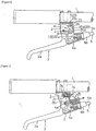
- a first embodiment of a bicycle braking device will be described with reference to Figure 1.
- a lever bracket (2) for the brake lever is attached to the handle-bar (1) of the bicycle, and a brake lever (3) is mounted on the lever bracket (2) by means of a pivot shaft (4) so that the brake lever (3) is free to pivot.
- An attachment part (6a) which is used to attach one end of the inner wire (5a) of the brake wire (5) to the brake lever (3) is pivot-mounted on the brake lever (3) in a position located further toward the grip part (3a) of the brake lever (3) than the pivot shaft (4).
- An attachment part (6b) for the outer wire (5b) of the brake wire (5) is screw-attached to the lever bracket (2).
- the other end of the inner wire (5a) attached to the inner-wire attachment part (6a) is coupled to an ordinary cantilever brake (7).
- the brake shoes (8) the brake shoes (8) of the cantilever brake (7) press against both sides of the rim of the rear wheel (9) of the bicycle so that a braking force is applied to the rear wheel (9).
- the brake lever (3) is released, the brake lever (3) is elastically returned to its original position in the same manner as in a conventional braking device by a return spring (not shown) installed on the cantilever brake (7) or a return spring installed on the brake lever (3), etc.
- a cylindrical body (2a) which is closed at one end is formed as an integral part of the lever bracket (2), and a rod-form body (10) which has a male screw part formed at one end is positioned inside this cylindrical body (2a).
- the male screw part of this rod-form body (10) is passed through a through-holed formed in the bottom of the cylindrical body (2a) so that the male screw parts extends to the outside, and a nut member (11) is screwed onto this male screw part.
- a flange (10a) is formed as an integral part of the rod-form body (10) on the other end of the rod-form body (10), and a contact member (12) which consists of a wear-resistant material is fastened to the flange (10a).
- a coil spring (13) which is mounted around the outside of the rod-form body (10) is interposed in a compressed state between the flange (10a) and the bottom of the cylindrical body (2a), so that the contact member (12) is elastically driven toward the open end of the cylindrical body (2a).
- An extension part (3b) used for pushing is formed as an integral extension of the brake lever (3) on the opposite side of the pivot shaft (4) from the grip part (3), so that when the brake lever (3) is gripped and pulled, the extension part (3b) contacts the contact member (12) after the brake lever (3) is pivoted through a fixed stroke, thus temporarily preventing further pivoting of the brake lever (3).
- the pivoting operation of the brake lever (3) is temporarily prevented by the action of a resistance means (14) consisting of the rod-form body (10) and coil spring (13), etc.
- the coil spring (13) is not installed in a fully extended free state, but is instead installed in a preloaded state with a load of approximately 3 kilograms to 8 kilograms applied. Accordingly, even if an attempt is made to pull the brake lever (3) further from the position of operating point (B), the operating force merely increases without causing any pivoting of the brake lever (3). As a result, the braking force remains level as shown in Figures 3 and 5.
- the braking device of the present invention is designed so that there is a region where the braking force remains constant at the set value (P) while only the operating force of the brake lever (3) increases as indicated by the region extending from operating point (B) to operating point (C) in Figure 3.
- this set value (P) at a value which is slightly lower than the locking braking force value (Q), and setting the preloading value at an appropriate value, it is possible to prevent the braking force from suddenly reaching the locking braking force value (Q), even if (for example) the force required in order to operate the brake lever (3) in the region extending from operating point (A) to operating point (B) is greatly reduced.
- most braking is performed with a braking force which is less than the locking braking force value (Q)
- safe braking which is suited to actual conditions can be achieved. Even so, there may be cases in which a braking force greater than the locking braking force value (Q) is required. In such cases, a rather large operating force is required; nevertheless, a braking force exceeding the locking braking force value (Q) can be reliably obtained by applying an operating force exceeding that shown at operating point (C).
- the above mentioned locking braking force value (Q) is influenced by the physical build of the cyclist, and especially by the cyclist's body weight. Adjustments can be made for this by increasing or decreasing the extension of the brake wire (5). It would also be possible to deal with this problem by installing a multiple number of coil springs (13) with different elastic modulus values or lengths (e. g., one spring for use by children, one for use by adults, one for use by women, etc.), and selecting the appropriate spring from this multiple number of springs.
- the preloading value of the coil spring (13) is ordinarily in the range of 3 kilograms to 8 kilograms; however, this is also influenced by the strength of the cyclist's grip, etc. Accordingly, the preloading value can be adjusted to suit individual cyclists by adjusting the nut member (11), and depending on the case, it might also be possible to replace the coil spring (13) with a more appropriate coil spring.
- Fig. 4 illustrates a second embodiment of a bicycle brake device according to the present inventio.
- a lever bracket (2) is fastened to the handle-bar (1) of the bicycle, and a brake lever (3) is mounted on the lever bracket (2) by means of a pivot shaft (4) so that the brake lever (3) is free to pivot.
- An attachment part (6a) for the inner wire (5a) is pivot-mounted on the brake lever (3) in a position located further toward the grip part (3a) of the brake lever (3) than the pivot shaft (4), and an attachment part (6b) for the outer wire (5b) is screw-attached to the lever bracket (2).
- the brake lever (3) is coupled to a cantilever brake (not shown) by the inner wire (5a), so that braking can be accomplished by pulling the brake lever (3).
- This second embodiment differs from the first embodiment in terms of the concrete structure of the resistance means (14).
- another pivot shaft (15) is mounted on the lever bracket (2) in a location closer to the handle-bar (1) than the pivot shaft (4), and a pivoting arm (16) is attached to the pivot shaft (15) so that the pivoting arm (16) is free to pivot.
- a rotating roller (16a) is attached to the free end of this pivoting arm (16) so that the roller (16) is free to rotate, and this rotating roller (16) is elastically driven by a torsion coil spring (17) interposed between the pivoting arm (16) and lever bracket (2), so that the roller (16) is maintained in contact with the inside surface of the brake lever (3).
- a cam surface (18) which has a resistance step part (18a) is formed on the inside surface of the brake lever (3), so that a resistance means (14) is constituted by this cam surface (18), the pivoting arm (16) and rotating roller (16a), and the spring (17), etc.
- the braking force increases in proportion to the operating force in the region extending from operating point (A) to the set operating position (B) (following "empty pulling"), as is shown in Figure 5.
- This set operating position (B) is the position where the rotating roller (16a) reaches the resistance step part (18a) of the cam surface (18) of the brake lever (3) (as indicated by the imaginary lines in Figure 4) after rolling across the cam surface (18) during the pulling operation of the brake lever (3). Even if an attempt is made to pull the brake lever (3) further, the operating force merely increases without any pivoting of the brake lever (3); accordingly, the braking force is maintained at the set value (P).
- the rotating roller (16) slips over the resistance step part (18a) (as indicated by the imaginary lines in Figure 4) so that the brake lever (3) reaches the stroke end (D).
- the resistance means (14) consisting of the rotating roller (16a) and cam surface (18), etc., produces an effect similar to that obtained in the first embodiment.
- the operating force at the stroke end (D) is clearly larger than the operating force at operating point (C); furthermore, since force is required for the elastic deformation of the coil spring (13) in the region extending from operating point (C) to the stroke end (D), the slope of the curve shown in Figure 3 is somewhat gentler in the region extending from operating point (C) to the stroke end (D) than it is in the region extending from operating point (A) to the set operating position (B).
- a cantilever brake (7) was described as an example of the brake used. However, there are no particular restrictions on the brake itself; a hand brake, coaster brake or any of various other types of brakes may also be used.
- the cylindrical body (2a) was formed as an integral part of the lever bracket (2) from the same material as the lever bracket (2). However, it would also be possible to form the cylindrical body (2a) separately from the lever bracket (2). Furthermore, in addition to forming the cylindrical body (2a) as a separate part, it would also be possible to construct the cylindrical body (2a) so that it can slide relative to the bracket (2), and so that it can be fixed in place as desired, thus making it possible to alter the stroke of the brake lever (3) to the operating point (B).
- the elastic body (13) is not limited to a coil spring. Various other types of elastic bodies could be used; for example, the elastic body (13) could be formed from ordinary rubber, or a part combining rubber and a spring, etc., could be used.
- a resistance means (14) offers a braking performance similar to that obtained in the first embodiment illustrated in Figure 3.
- a brake lever (3) is mounted on a lever bracket (2) by means of a pivot shaft (4) so that the brake lever (3) is free to pivot, and a cam surface (22) is formed as an integral part of the brake lever (3) near the pivot shaft (4).
- This cam surface (22) consists of (a) a circular-arc-form first cam surface (22a) which has a constant radius of R centered on the pivot shaft (4), (b) an involute-curve-form third cam surface (22c) whose distance from the pivot shaft (4) is greater than the constant radius R, with the distance from the pivot shaft (4) showing a gradual increase, and (c) a projection-form second cam surface (22b) which connects the cam surfaces (22a) and (22c).
- a pivoting member (24) is mounted on the lever bracket (2) by means of a pivot shaft (23) which is separate from the pivot shaft (4) of the brake lever (3), so that the pivoting member (24) is free to pivot.
- the outer wire (5b) of the brake wire is attached to an attachment part (6b) which is screw-fastened to the pivoting member (24), so that the pivoting member (24) is driven toward the cam surface (22) in a pivoting motion about the pivot shaft (23) by the reaction force of the outer wire (5b).
- a roller (24a) which contacts the cam surface (22) and acts as a cam follower is pivot-mounted on the pivoting member (24) so that the roller (24a) is free to rotate.
- a resistance means (14) is constituted by the pivoting part (24) (including the roller (24a)), the cam surface (22) and the outer wire (5b) which drives the pivoting part (24).
- the roller (24a) moves along the first cam surface (22a) of the cam surface (22) during so-called "empty pulling", and during the period in which the operating force gradually increases from operating point (A) where the brake shoes (8) contact the rim. Accordingly, there is no particular pivoting motion of the pivoting member (24), and the braking force increases in proportion to the pulling operation of the brake lever (3).
- the second cam surface (22b) formed on the brake lever (3) contacts the roller (24a) so that operating point (B) shown in Figure 3 is reached.
- the second cam surface (22b) is formed so that it projects abruptly outward from the first cam surface (22a).
- the operating force merely increases without causing any pivoting of the brake lever (3). Accordingly, the braking force remains level.
- the embodiment shown in Figure 7 is also a structure in which a brake lever (3) is mounted on a lever bracket (2) by means of a pivot shaft (4a) so that the brake lever (3) is free to pivot; in this structure, however, the pivot shaft (4a) is engaged in a slot (2b) formed in the lever bracket (2), so that the pivot shaft (4a) can move along the slot (2b). Furthermore, the pivot shaft (4a) is elastically driven in the direction indicated by the arrow in Figure 7 by a coil spring (25).
- a projecting pin (3c) which can engage with a recess (2c) formed in the lever bracket (2) is installed on the brake lever (3). Accordingly, a resistance means (14) is constituted by the above mentioned recess (2c), pin (3c), slot (2b) and pivot shaft (4a), etc.
- the brake lever (3) pivots about the pivot shaft (4a) during so-called "empty pulling", and during the period in which the operating force gradually increases from operating point (A) where the brake shoes (8) contact the rim. Accordingly, the braking force increases in proportion to the pulling operation of the brake lever (3).
- the projecting pin (3c) installed on the brake lever (3) engages with the recess (2b) formed in the lever bracket (2), so that operating point (B) shown in Figure 3 is reached.
- the resistance means By constructing the resistance means from a preloaded elastic body, it is possible to obtain a resistance means which has a complicated action by means of a relatively simple structure. Furthermore, by making the preloading applied to the elastic body adjustable, it is possible not only to deal with changes in elasticity caused by deterioration of the elastic body, but also to adjust the device so that it can be used under optimal conditions in accordance with the grasping force applied by various individual cyclists.
- the device is constructed so that (a) the elastic body consists of a coil spring, (b) the adjustment part consists of a nut member, (c) a rod-form body which is mounted inside the coil spring is passed through the lever bracket in such a manner that said rod-form body can move freely through said lever bracket, (d) the coil spring is mounted between (i) a contact member (which contacts the brake lever) installed on one end of the rod-form body, and (ii) the lever bracket, and (e) the nut member is screw-engaged with the other end of the rod-form body passed through the lever bracket, the structure obtained is relatively simple, and all of the above mentioned mechanisms can be mounted in a compact manner on the lever bracket.
Landscapes
- Engineering & Computer Science (AREA)
- Mechanical Engineering (AREA)
- Braking Arrangements (AREA)
Applications Claiming Priority (2)
| Application Number | Priority Date | Filing Date | Title |
|---|---|---|---|
| JP08421694A JP3577102B2 (ja) | 1994-04-22 | 1994-04-22 | 自転車用ブレーキ装置 |
| JP84216/94 | 1994-04-22 |
Publications (2)
| Publication Number | Publication Date |
|---|---|
| EP0678444A1 true EP0678444A1 (fr) | 1995-10-25 |
| EP0678444B1 EP0678444B1 (fr) | 1998-11-18 |
Family
ID=13824290
Family Applications (1)
| Application Number | Title | Priority Date | Filing Date |
|---|---|---|---|
| EP19950302569 Expired - Lifetime EP0678444B1 (fr) | 1994-04-22 | 1995-04-18 | Dispositif de freinage pour bicyclettes |
Country Status (3)
| Country | Link |
|---|---|
| EP (1) | EP0678444B1 (fr) |
| JP (1) | JP3577102B2 (fr) |
| DE (1) | DE69506025T2 (fr) |
Cited By (1)
| Publication number | Priority date | Publication date | Assignee | Title |
|---|---|---|---|---|
| US6155383A (en) * | 1996-06-11 | 2000-12-05 | Shimano, Inc. | Bicycle brake device |
Families Citing this family (1)
| Publication number | Priority date | Publication date | Assignee | Title |
|---|---|---|---|---|
| CN106143765B (zh) * | 2015-04-14 | 2019-04-16 | 核工业西南物理研究院 | 辅助安全刹车装置及其骑行车辆 |
Citations (4)
| Publication number | Priority date | Publication date | Assignee | Title |
|---|---|---|---|---|
| FR1349334A (fr) * | 1962-11-30 | 1964-01-17 | Nouveau dispositif permettant simultanément de freiner et de couper les gaz, en particulier dans le cas des vélomoteurs | |
| DE3923176A1 (de) * | 1988-07-15 | 1990-02-01 | Shimano Industrial Co | Bremsenregelvorrichtung fuer fahrraeder |
| DE9203082U1 (de) * | 1992-03-09 | 1992-05-07 | Fichtel & Sachs Ag, 8720 Schweinfurt | Handbetätigungseinrichtung für Bremsen an Fahrrädern o.dgl. mit Kraftbegrenzung |
| JPH0516865A (ja) * | 1991-07-10 | 1993-01-26 | Shimano Inc | 自転車用のブレーキ操作装置 |
-
1994
- 1994-04-22 JP JP08421694A patent/JP3577102B2/ja not_active Expired - Fee Related
-
1995
- 1995-04-18 EP EP19950302569 patent/EP0678444B1/fr not_active Expired - Lifetime
- 1995-04-18 DE DE1995606025 patent/DE69506025T2/de not_active Expired - Fee Related
Patent Citations (4)
| Publication number | Priority date | Publication date | Assignee | Title |
|---|---|---|---|---|
| FR1349334A (fr) * | 1962-11-30 | 1964-01-17 | Nouveau dispositif permettant simultanément de freiner et de couper les gaz, en particulier dans le cas des vélomoteurs | |
| DE3923176A1 (de) * | 1988-07-15 | 1990-02-01 | Shimano Industrial Co | Bremsenregelvorrichtung fuer fahrraeder |
| JPH0516865A (ja) * | 1991-07-10 | 1993-01-26 | Shimano Inc | 自転車用のブレーキ操作装置 |
| DE9203082U1 (de) * | 1992-03-09 | 1992-05-07 | Fichtel & Sachs Ag, 8720 Schweinfurt | Handbetätigungseinrichtung für Bremsen an Fahrrädern o.dgl. mit Kraftbegrenzung |
Non-Patent Citations (1)
| Title |
|---|
| PATENT ABSTRACTS OF JAPAN vol. 17, no. 288 (M - 1423) 3 June 1993 (1993-06-03) * |
Cited By (1)
| Publication number | Priority date | Publication date | Assignee | Title |
|---|---|---|---|---|
| US6155383A (en) * | 1996-06-11 | 2000-12-05 | Shimano, Inc. | Bicycle brake device |
Also Published As
| Publication number | Publication date |
|---|---|
| DE69506025D1 (de) | 1998-12-24 |
| EP0678444B1 (fr) | 1998-11-18 |
| JP3577102B2 (ja) | 2004-10-13 |
| JPH07291173A (ja) | 1995-11-07 |
| DE69506025T2 (de) | 1999-07-15 |
Similar Documents
| Publication | Publication Date | Title |
|---|---|---|
| US5924328A (en) | Braking device for bicycles | |
| US4974469A (en) | Support for the brake-operating lever and the gear-operating lever of bicycles and the like | |
| US6296082B1 (en) | Scooter rear wheel brake | |
| EP1342655B1 (fr) | Appareil d'ajustement pour dispositif de commande de frein de bicyclette | |
| EP0640051A1 (fr) | Mecanisme d'actionnement d'un ma tre cylindre hydraulique | |
| EP0934872B1 (fr) | Dérailleur arrière avec dispositif amortisseur | |
| JP2537504B2 (ja) | ブレ―キ圧接力制御装置 | |
| US4862999A (en) | Device for braking a bicycle | |
| EP0831020A2 (fr) | Frein sur jante de bicyclette | |
| EP0678444B1 (fr) | Dispositif de freinage pour bicyclettes | |
| US5566789A (en) | Bicycle anti-locking brake | |
| US4015690A (en) | Bicycle brake with force modifying means | |
| US4903799A (en) | Brake-operating lever, with an adjustable transmission ratio | |
| US6112614A (en) | Brake lever stroke adjusting mechanism | |
| US4579189A (en) | Two-wheeled motor vehicle anti-lift device | |
| CN101214815B (zh) | 一种工业车辆的制动器 | |
| EP0709284B1 (fr) | Dispositif de commande de frein pour bicyclettes | |
| JP2901381B2 (ja) | 自転車用のブレーキ操作装置 | |
| US8333266B2 (en) | Brake system and method and two-wheeled vehicle using the same | |
| WO2001038151A1 (fr) | Pedale et tringlerie de reduction de force | |
| CN1051514C (zh) | 自行车用制动装置 | |
| WO2021105891A1 (fr) | Dispositif pour le réglage automatique du jeu d'un frein de stationnement | |
| JPH0343914Y2 (fr) | ||
| CA2192872A1 (fr) | Frein a moyeu pour bicyclettes | |
| GB2344859A (en) | A bicycle v-type brake |
Legal Events
| Date | Code | Title | Description |
|---|---|---|---|
| PUAI | Public reference made under article 153(3) epc to a published international application that has entered the european phase |
Free format text: ORIGINAL CODE: 0009012 |
|
| AK | Designated contracting states |
Kind code of ref document: A1 Designated state(s): DE FR GB IT |
|
| 17P | Request for examination filed |
Effective date: 19960109 |
|
| 17Q | First examination report despatched |
Effective date: 19970227 |
|
| GRAG | Despatch of communication of intention to grant |
Free format text: ORIGINAL CODE: EPIDOS AGRA |
|
| RAP1 | Party data changed (applicant data changed or rights of an application transferred) |
Owner name: SHIMANO INC. |
|
| GRAG | Despatch of communication of intention to grant |
Free format text: ORIGINAL CODE: EPIDOS AGRA |
|
| GRAH | Despatch of communication of intention to grant a patent |
Free format text: ORIGINAL CODE: EPIDOS IGRA |
|
| GRAH | Despatch of communication of intention to grant a patent |
Free format text: ORIGINAL CODE: EPIDOS IGRA |
|
| GRAA | (expected) grant |
Free format text: ORIGINAL CODE: 0009210 |
|
| AK | Designated contracting states |
Kind code of ref document: B1 Designated state(s): DE FR GB IT |
|
| REF | Corresponds to: |
Ref document number: 69506025 Country of ref document: DE Date of ref document: 19981224 |
|
| ITF | It: translation for a ep patent filed | ||
| ET | Fr: translation filed | ||
| PGFP | Annual fee paid to national office [announced via postgrant information from national office to epo] |
Ref country code: GB Payment date: 19990406 Year of fee payment: 5 |
|
| PLBE | No opposition filed within time limit |
Free format text: ORIGINAL CODE: 0009261 |
|
| STAA | Information on the status of an ep patent application or granted ep patent |
Free format text: STATUS: NO OPPOSITION FILED WITHIN TIME LIMIT |
|
| 26N | No opposition filed | ||
| PG25 | Lapsed in a contracting state [announced via postgrant information from national office to epo] |
Ref country code: GB Free format text: LAPSE BECAUSE OF NON-PAYMENT OF DUE FEES Effective date: 20000418 |
|
| GBPC | Gb: european patent ceased through non-payment of renewal fee |
Effective date: 20000418 |
|
| PGFP | Annual fee paid to national office [announced via postgrant information from national office to epo] |
Ref country code: IT Payment date: 20090422 Year of fee payment: 15 Ref country code: FR Payment date: 20090417 Year of fee payment: 15 Ref country code: DE Payment date: 20090420 Year of fee payment: 15 |
|
| REG | Reference to a national code |
Ref country code: FR Ref legal event code: ST Effective date: 20101230 |
|
| PG25 | Lapsed in a contracting state [announced via postgrant information from national office to epo] |
Ref country code: DE Free format text: LAPSE BECAUSE OF NON-PAYMENT OF DUE FEES Effective date: 20101103 |
|
| PG25 | Lapsed in a contracting state [announced via postgrant information from national office to epo] |
Ref country code: IT Free format text: LAPSE BECAUSE OF NON-PAYMENT OF DUE FEES Effective date: 20100418 |
|
| PG25 | Lapsed in a contracting state [announced via postgrant information from national office to epo] |
Ref country code: FR Free format text: LAPSE BECAUSE OF NON-PAYMENT OF DUE FEES Effective date: 20100430 |