EP0678449A1 - Dispositif pour mesurer et distribuer des quantités prédeterminées d'un matériau pulvérulent - Google Patents
Dispositif pour mesurer et distribuer des quantités prédeterminées d'un matériau pulvérulent Download PDFInfo
- Publication number
- EP0678449A1 EP0678449A1 EP95105552A EP95105552A EP0678449A1 EP 0678449 A1 EP0678449 A1 EP 0678449A1 EP 95105552 A EP95105552 A EP 95105552A EP 95105552 A EP95105552 A EP 95105552A EP 0678449 A1 EP0678449 A1 EP 0678449A1
- Authority
- EP
- European Patent Office
- Prior art keywords
- distributors
- shaft
- carrousel
- regulation
- volume
- Prior art date
- Legal status (The legal status is an assumption and is not a legal conclusion. Google has not performed a legal analysis and makes no representation as to the accuracy of the status listed.)
- Withdrawn
Links
Images


Classifications
-
- A—HUMAN NECESSITIES
- A61—MEDICAL OR VETERINARY SCIENCE; HYGIENE
- A61J—CONTAINERS SPECIALLY ADAPTED FOR MEDICAL OR PHARMACEUTICAL PURPOSES; DEVICES OR METHODS SPECIALLY ADAPTED FOR BRINGING PHARMACEUTICAL PRODUCTS INTO PARTICULAR PHYSICAL OR ADMINISTERING FORMS; DEVICES FOR ADMINISTERING FOOD OR MEDICINES ORALLY; BABY COMFORTERS; DEVICES FOR RECEIVING SPITTLE
- A61J3/00—Devices or methods specially adapted for bringing pharmaceutical products into particular physical or administering forms
- A61J3/07—Devices or methods specially adapted for bringing pharmaceutical products into particular physical or administering forms into the form of capsules or similar small containers for oral use
- A61J3/071—Devices or methods specially adapted for bringing pharmaceutical products into particular physical or administering forms into the form of capsules or similar small containers for oral use into the form of telescopically engaged two-piece capsules
- A61J3/074—Filling capsules; Related operations
-
- B—PERFORMING OPERATIONS; TRANSPORTING
- B65—CONVEYING; PACKING; STORING; HANDLING THIN OR FILAMENTARY MATERIAL
- B65B—MACHINES, APPARATUS OR DEVICES FOR, OR METHODS OF, PACKAGING ARTICLES OR MATERIALS; UNPACKING
- B65B1/00—Packaging fluent solid material, e.g. powders, granular or loose fibrous material, loose masses of small articles, in individual containers or receptacles, e.g. bags, sacks, boxes, cartons, cans, or jars
- B65B1/30—Devices or methods for controlling or determining the quantity or quality or the material fed or filled
- B65B1/36—Devices or methods for controlling or determining the quantity or quality or the material fed or filled by volumetric devices or methods
- B65B1/38—Devices or methods for controlling or determining the quantity or quality or the material fed or filled by volumetric devices or methods by pistons co-operating with measuring chambers
- B65B1/385—Devices or methods for controlling or determining the quantity or quality or the material fed or filled by volumetric devices or methods by pistons co-operating with measuring chambers moving in an endless path
Definitions
- the invention relates to machines for packaging doses of medicinal product in hard gelatine capsules.
- the invention relates to an apparatus for measuring and dispensing predetermined amounts of powdered material used in composite machines of the type which operate intermittently and are provided with at least one vertical axis carrousel, to which there are attached the bodies of tube-type volumetric distributors which are also vertical, with the open end of the tube oriented downwards, at which end a movable plunger is thrust upwards by elastic means, and is provided radially with a projection which extends from the said body through a longitudinal slot, and which is normally supported against stops which are supported by a plate fitted onto the said carrousel, and connected to the latter by axial adjustment means.
- the said plate with the stops can be lowered or raised in order to raise or lower the plunger of the distributors, and thus respectively increase or decrease the useful volume of the tube of the distributors.
- the tube-type distributors are mounted on the carrousel in two opposite groups, and the carrousel is alternately rotated by 180° and raised and lowered in order to insert the tube of a group of distributors in a store beneath, which contains a correct layer of the product in powder and/or granule form to be distributed, such that the free chamber of the tube is filled uniformly with product.
- the distributors are plunged into the store of product, then raised, rotated by 180° and aligned with the bases of capsules which are supported by the carrousel for handling the hard gelatine capsules.
- the distributors with the dose of product are lowered and abutted with the base of the capsules into which they unload the dose of product when respective thrust devices act on the movement pieces of the distributors.
- the thrust devices rise in order to enable the plunger of the distributors to return resiliently into the high, cycle start position, after which the distributors are also raised and returned to co-operate with the store of product, for repetition of a new work cycle.
- the object of the invention is to eliminate these and other disadvantages, by means of the following solution.
- the shaft of the carrousel is axially hollow, and another shaft is inserted therein, the upper end of which is kinematically connected to the means of axial adjustment of the plate with the stops for stopping the movement pieces of the tube-type distributors.
- the lower ends of the two shafts are grooved, and are kinematically connected to one another by means of two sets of gears and a reduction/differential gear unit which supports a two-way electric motor provided with a brake which is fitted on the adjustment shaft.
- An encoder is also provided, for detecting the phase and speed of rotation of the said inner shaft of the distributor carrousel.
- the kinematic mechanism which comprises the said reduction/differential gear unit is such that the rotation which the main motor of the machine transmits to the said outer shaft of the distributor carrousel, is transmitted to the inner shaft at the same speed and in the same direction.
- the said adjustment motor of the reduction/differential gear unit is actuated in the direction of rotation required, thus giving rise to rotation of the inner shaft in the correct direction relative to the outer shaft, and to consequent axial movement of the upper plate with the stops for the movement pieces of the distributors, to which the necessary correction is thus made.
- This adjustment can be carried out whether the distributor carrousel is at a standstill or rotating.
- a processor monitors the speed of rotation of the two co-axial shafts, and controls and monitors the extent of sliding to be imparted to these shafts, with activation of the inner shaft, in order to obtain the necessary correction of volume of the distributors.
- This processor is provided with the data for setting the volume of the distributors and/or for the necessary corrections of the volume, via a keyboard and screen, and via the weighing system which monitors cyclically the weight of the full capsules of product when closed and unloaded from the machine.
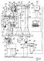
- 1 indicates a carrousel of a known type for supporting tube-type volumetric distributors, the vertical shaft 2 of which is supported such as to rotate by the support 3, and is provided in an intermediate part with a pinion 4 of a height suitably greater than the axial movement to which this shaft is cyclically subjected (see below), and which by means of the gear pair 5 is connected to a device 6 of a known type, the input 7 of which is connected to the main motor unit 100 (figure 3) of the carrousel 200 for handling the capsules of hard gelatine (see below), and which at each rotational step of this carrousel, transmits to the said shaft 2 an alternate 180° rotation, as indicated by the arrow 8.
- the same shaft 2 is provided in an intermediate part with an annular recess 9 which is engaged by the rollers 10 of the forked end of a lever 11, which is pivoted at 12 to a fixed support, and which by means of an intermediate button 13 co-operates with the profile of a cam 14 which rotates on the shaft 15, and is activated by the device of a known type schematically indicated 6, connected in phase with the carrousel 200 for handling the hard gelatine capsules, all such that after each alternate 180° rotation, when the said carrousel 200 is at a standstill, the shaft 2 is raised and lowered by the correct amount.
- a small piston 18 which is associated with a piece 19 which is driven axially in the body of the distributors, is thrust upwards by a spring 20, and in its top part is provided radially with a pin 21 which projects from the said body through at least one longitudinal slot, not shown, and is normally supported on the stops 22 of a plate 23 which is parallel to the carrousel 1 and is provided with holes 24 for free passage of the body of the distributors.
- the plate 23 is normally provided with guide bushes 25 through which there slide vertical pins 26 which are integral with the carrousel 1, and is provided in its centre with a barrel nut 27 which co-operates with the screw 28, which according to the known art is mounted such as to rotate on the said carrousel 1.
- the screw 28 provides axial connection of the plate 23 to the carrousel 1, whereas the bushes and pins 25, 26 provide the necessary guidance between the two parts.
- the axial position of the plate 23 determines the distance between the small piston 18 and the lower free edge of the tubes of the distributors, and thus the volume of the product distribution chamber. In order to vary this volume, it is necessary to screw or unscrew the screw 28, as described in the introduction of the present description.
- the tube-type distributors 116 are disposed for example above a store 29 containing a correct layer of product 30 into which the distributors are plunged such that their lower chamber is filled with product.
- optional thrust devices 31 which are mounted in a known manner on a structure 82 with the interposition of registers 32, which thrust devices compact correctly the dose of product inserted in the lower chamber of the distributors, after which the said thrust devices are raised, and the carrousel 1 is also raised in order to extract the distributors from the store 29, and is then rotated in order to transfer the distributors 116 to the position of those 16 and vice versa.
- the distributors 116 Whilst the distributors 116 are aligned with the store 29 and are lowered into the latter in order to collect the dose of product as previously described, on the opposite side the distributors 16 containing the dose of product 33 are lowered above the base 34 of a hard gelatine capsule, which is supported by one of the angularly equidistant and radially mobile seats 35 of the carrousel 200, which handles the capsules (see below), and which supports, above the seats 35, corresponding fixed seats 36 for accommodating the cover 37 of the capsules.
- the thrust devices 131 which are mounted on the structure 82 with registers 132 act, in order to thrust axially downwards the plunger 18 of the distributors, and to unload the dose of product 33 into the base 34 of the capsule, after which the thrust devices 131 are raised and the carrousel 200 rotates by one step in order to allow the distributors 16 to return to the condition required for the purpose of dosing the product.
- the base of the capsules can co-operate with a plurality of distribution carrousels for various products, after which the supports 35 are returned to the original position in which the base 34 is aligned axially with the cover 37, such that appropriate means can raise the base in order to connect it to the cover, and then unload from the carrousel into the station indicated 300 the hard gelatine capsules which are closed and contain the dose or doses of product.
- the capsules which are unloaded from the station 300 of the carrousel 200 reach the means 38 of unloading via an exchange device 39 which is activated cyclically in order to divert the capsules one at a time to at least one weighing unit 40 from which the capsules are then returned to the means 38 of unloading, if their weight is correct, or otherwise are unloaded into other collection means.
- the weighing unit 40 provides the data concerning the weight of the capsules full of product, which data is used according to the known art in order to inform the operator of any need to regulate the volume of the distributors and, within the context of the present invention, is used as described above.
- the parts 27 and 28 are made with precision components, for example of the recirculating ball type, and as illustrated in figure 1, the screw 28 is released from the carrousel 1 and is attached to the upper end of a shaft 41 which passes axially through the shaft 2, which is hollow for this purpose.
- the lower ends of the two shafts each have a grooved shape, as indicated at 42 and 43, such that one projects from the other, and both are inserted in a laterally sealed manner in a fixed box 44, in which the following kinematic devices operate with an oil bath.
- the grooved end 42 of the shaft 2 engages with the mating inner profile 142 of a ring gear 45 which is supported such as to rotate by the support 46, whereas the grooved end 43 of the shaft 41 co-operates with the mating inner profile 143 of a ring gear 47 which is supported such as to rotate by the support 48, both the supports 46 and 48 being attached to the inner projection 49 of the said box 44.
- a hollow hub 50 which projects from the base of the box 44 through lateral sealing means 51, is supported such as to rotate on the bearings 52 by the support 53 which is attached to the base of the box 44, and to the lower part of which there is flanged the body of an encoder 54, the axis of which is connected to the hub 50 by connecting means 55.
- the support 53 is for example surrounded by a robust bush 56 flanged at the upper end to the base of the box 44, and attached at its lower end to an extension of the base 57 of the carrousel 1.
- the electrical cable of the encoder 54 passes out through a window 58 in the said support bush 56.
- the axial cavities of the ring gears 45, 47, and the axial cavity of the hub 50 have dimensions such as to permit the necessary axial movement of the shaft 2 and the associated shaft 41 of the carrousel 1.
- the inner part 67 On the intermediate part of the shaft 61 there is keyed by means of the key 66 the inner part 67, the so-called wave generator, of a type HDUA-2F HARMONIC DRIVE reduction / differential gear, with any suitable reduction ratio, the structural details of which are not described as they are known.
- 68 and 69 indicate the outer rings of input and output of motion into and from the reduction/differential gear unit, known respectively as the circular spline and dynamic spline.
- the rings 68 and 69 are attached co-axially to respective ring gears 70, 71, which are mounted such as to rotate on the shaft 61 with the bearings 72, 73 and which engage with respective idle toothed wheels 74, 75 mounted such as to rotate freely on the shaft 76, which is supported by the inner projection 49 of the box 44 and is parallel to the shaft 61.
- the dimensions of the gears 45, 74, 70, and 71, 75, 47 depend on the reduction ratio of the Harmonic Drive used, and are such that when the motor 63 is at a standstill, the inner shaft 41 rotates at exactly the same speed and in the same direction as the shaft 2 of the carrousel 1.
- the system in figure 2 is also such that when the machine is operating, if the motor 63 is actuated to rotate in either direction, by means of the Harmonic Drive a very slow acceleration or deceleration of the shaft 41 is induced, in the direction appropriate for screwing or unscrewing the screw 28, and consequently raising or lowering the plate 23 in figure 1, for the required regulation of volume of the distributors.
- the system in figure 2 is also such that when the machine is at a standstill, if the motor 63 is actuated to rotate in either direction, this gives rise to slow rotation of the shaft 41 in the fixed shaft 2, for volumetric setting of the distributors to the condition required in the individual cases in the work cycle (see below).
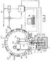
- FIG 3 shows that the data obtained from the weighing unit 40 is transmitted to a central processing unit or processor 77, which by means of an interface activates cyclically the exchange 39.
- a central processing unit or processor 77 Adjacent to this unit 77, there is a keyboard/screen unit 78 for the operations of programming and interrogation, and also connected are the encoder 54, and by means of an interface, the above-mentioned motor 63; there is also connected thereto the encoder 79 which measures the rotation and phase of the carrousel 200 for handling the hard gelatine capsules, and all the parts which derive motion directly from this carrousel, including the outer shaft 2 of the distributor carrousel.
- a sensor 80 which is attached for example to an arm 81 which is integral with a fixed part of the carrousel 200, and which, as illustrated in figure 1, is located so as to detect the position of maximum raising of the plate 23, and the consequent condition of maximum volume of the tube distributors of the carrousel 1.
- the plate 23 automatically goes into the highest raised position, in co-operation with the said sensor 80.
- the torque limiter 64 permits stoppage of the plate 23 against end of travel stops, not shown, without the system being damaged.
- the limiter 64 also intervenes in the event of obstacles to regulation.
- the volume of the distributors is regulated to the predetermined value.
- the processor 77 activates the motor 63 in the correct direction, detects the extent of movement in progress via the encoder 54, and when the predetermined values have been reached, stops the said motor which to this end will be provided with a brake.
- the processor 77 reads the weight information of the full capsules which are unloaded from the station 300 of the machine 200, and are weighed cyclically by the unit 40, and compares the data read with that initially obtained from the keyboard 78. If the weight data read differs from that programmed, the processor detects whether these values are deficient or in excess, determines the extent thereof, and if necessary, rotates the motor 63 in the correct direction in order to implement the required regulation of volume of the distributors, which is checked by comparison of the signals obtained from the encoders 79 and 54, all in a manner which can be devised and easily performed by persons skilled in the art.
- the processor 77 stops operation of the machine, and can be set to indicate the cause of stoppage to the unit 78.
- the improved machine according to the invention can be controlled even by employees who are not highly qualified, since it carries out automatically regulations of volume of the distributors, without needing any stoppage, and since it can eliminate with the greatest possible safety and technological reliability all the disadvantages of the known art. All the means which regulate the volume of the distributors are disposed externally, and below the working environment of the distributors, where conditions of controlled atmosphere can optionally be introduced, such as to prevent any pollution of this environment.
- the said thrust devices 31-131 In order to operate the thrust devices 31-131 with the necessary force for the compression of the product insulated in the tubes of the distributors and thereafter for the expulsion of the dose compressed by the said distributors, the said thrust devices are usually shifted with mechanical systems cam or lever operated and with the interposition of mechanical registers 32-132 enabling a correct setting up of the machine during its construction.
- the mechanical movement systems works with a predetermined and fixed stroke, so that in order to maintain constant the degree of compression of the dose of product in the distributors, each time that same are registered in volume by their own means, it is necessary to register, through the registers 32 the position in height of the thrust devices 31, in a measure which is directly proportional to the lifting of the piston of the said distributors.
- This registration is instead not requested for the thrust devices 131 for discharging the doses of product from the distributors, which operate with a fixed stroke which is necessary for the expulsion of the greater and higher dose.
- the rod 83 is lowered together and in synchrony with the shaft 2 and as the latter is stopped, the said rod continues in its downward movement with a fixed stroke by effect of which the thrust devices 31-131 effect respectively the compression of the doses of product in the distributors 116 and the expulsion of the product doses from the distributors 16. Thereafter the shaft 2 is lifted thus lifting also the rod 83, by such a law that when the said shaft is lifted up, the thrust devices 31-131 are out of cooperation with the distributors and are in their high position of starting of a cycle.
- the body of the registers 32 is mounted with the possibility of axial shifting within suitable vertical guide seats 86 carried by the said structure together with means for the axial registration which for example comprise a vertical screw 87 rotatably supported at the ends by the same structure 82 which is fork-like shaped for this purpose and which cooperates with a nut screw 88 secured to a support 188 to which the body of the registers 32 is secured.
- means for the axial registration which for example comprise a vertical screw 87 rotatably supported at the ends by the same structure 82 which is fork-like shaped for this purpose and which cooperates with a nut screw 88 secured to a support 188 to which the body of the registers 32 is secured.
- the structure 82 supports rotatably, for example through its portion 182 supporting also the upper end of the screw 87, the upper portion of a vertical shaft 89 sliding in the suitable fixed guide 90 and which, by its lower end penetrates in the basement of the machine to cooperate with the means which will be described later.
- the shaft 89 is lifted and lowered together with the structure 82 and with the rod 83.
- the same portion 182 of the structure 82 is carrying a box 191 containing a positive motion transmission , and for example a gear 91, connecting kinematically the shaft 89 to the screw 87.
- the lower end of the shaft 89 is, for example provided with longitudinal grooves 189 by which the same shaft is axially shifted while remaining concurrently coupled to an axially grooved pinion 192 of a gear 92 accomodated inside of a box 93 secured to a support 156 and on which the body of a motor 94 with electronic speed and phase control and provided with own braking means is flanged.
- the motor 63 effecting the remote adjustment of the volume of the distributors is preferably of the same kind as the motor 94 previously described.
- transducers for linear movements for example of the kind known under the name LVDT, utilizing the principle of the electric differential transformer and which transform the distance between the two parts on which they are mounted, in an electric signal which varies with the variation of the distance.
- One of said transducers 154 is substituting the one 54 of Figure 2 and is mounted between the carousel 1 and the plate 23 so as to detect the reciprocal movement of said two parts as a consequence of the variations in volume of the distributors.
- the other transducer 95 is mounted between the supports 188 and 82 so as to detect the linear movement between said two components in consequence of the variations of position in height of the registers 32.
- the processor 77 Each time that the processor 77 detects from the weighing unit 40 an improper weight value and controls the activation of the motor 63 for the registering of the volume of the distributors, with control in feedback through the transducer 154, at the same time the same processor controls the activation of the motor 94 so as to register according to a predetermined algorithm the position in height of the registers 32 which is controlled in feedback through the transducer 95.
- the guide 90 can be eliminated and that the shaft 89 can be arranged axially inside of the rod 83, thus semplifying also the trasmission 91 of the movement, in a manner which is easily conceivable and which may be easily made by an expert in this field.
- the rod 83 will be blocked by known mens against rotation about its axis, which is a condition which in the solution of Figure 4 is assured by the shaft 89 and by the guide 90.
- the bellows-like protections for the screws 87 and 28 have been omitted, as well as other safety means, also of the structural type, inasmuch as not necessary for the comprehension of the invention and because they are evident to the experts and also because they are in part known.
Landscapes
- Health & Medical Sciences (AREA)
- Engineering & Computer Science (AREA)
- Veterinary Medicine (AREA)
- Chemical & Material Sciences (AREA)
- Life Sciences & Earth Sciences (AREA)
- Animal Behavior & Ethology (AREA)
- General Health & Medical Sciences (AREA)
- Public Health (AREA)
- Medicinal Chemistry (AREA)
- Pharmacology & Pharmacy (AREA)
- Quality & Reliability (AREA)
- Mechanical Engineering (AREA)
- Basic Packing Technique (AREA)
- Apparatus For Radiation Diagnosis (AREA)
- Details Of Television Systems (AREA)
- Closed-Circuit Television Systems (AREA)
Applications Claiming Priority (2)
| Application Number | Priority Date | Filing Date | Title |
|---|---|---|---|
| IT94BO000175A ITBO940175A1 (it) | 1994-04-22 | 1994-04-22 | Dispositivo per la teleregolazione del volume di dosatori montati su una giostra, particolarmente per le macchine adibite al |
| ITBO940175 | 1994-04-22 |
Publications (1)
| Publication Number | Publication Date |
|---|---|
| EP0678449A1 true EP0678449A1 (fr) | 1995-10-25 |
Family
ID=11339734
Family Applications (1)
| Application Number | Title | Priority Date | Filing Date |
|---|---|---|---|
| EP95105552A Withdrawn EP0678449A1 (fr) | 1994-04-22 | 1995-04-12 | Dispositif pour mesurer et distribuer des quantités prédeterminées d'un matériau pulvérulent |
Country Status (3)
| Country | Link |
|---|---|
| US (1) | US5626171A (fr) |
| EP (1) | EP0678449A1 (fr) |
| IT (1) | ITBO940175A1 (fr) |
Cited By (6)
| Publication number | Priority date | Publication date | Assignee | Title |
|---|---|---|---|---|
| WO2000032151A1 (fr) * | 1998-12-03 | 2000-06-08 | I.M.A. Industria Macchine Automatiche S.P.A. | Dispositif de verification et de commande, utile dans des machines de conditionnement sous gelules |
| EP1240885A3 (fr) * | 2001-03-16 | 2002-12-11 | H.P.F. S.r.l. | Dispositif pour remplir des gélules d'au moins un produit |
| EP1240884A3 (fr) * | 2001-03-16 | 2002-12-11 | H.P.F. S.r.l. | Machine pour remplir des capsules avec un produit pulvérulent |
| WO2002092430A3 (fr) * | 2001-05-15 | 2003-01-30 | Ima Spa | Machine automatique de remplissage de flacons de materiau pulverulent et mecanisme d'entrainement associe |
| US7051771B2 (en) | 2002-02-07 | 2006-05-30 | Pfizer Limited | Method and apparatus for introducing powder into a pocket |
| ITSA20120013A1 (it) * | 2012-10-30 | 2014-05-01 | Auria Cosimo D | Macchina pneumatica dispenser di basilico in foglia |
Families Citing this family (24)
| Publication number | Priority date | Publication date | Assignee | Title |
|---|---|---|---|---|
| IT1290425B1 (it) * | 1996-10-22 | 1998-12-03 | Dott Bonapace & C Srl | Dispositivo dosatore di sostanze pulverulente per macchine per il riempimento di opercoli |
| DE10001068C1 (de) * | 2000-01-13 | 2001-05-31 | Bosch Gmbh Robert | Vorrichtung zum Dosieren und Abgeben von Pulver in Hartgelatinekapseln oder dergleichen |
| US6347650B1 (en) * | 2000-06-16 | 2002-02-19 | Discovery Partners International, Inc. | Device and method for dispensing particulate material |
| DE10211118A1 (de) * | 2002-03-14 | 2003-09-25 | Bosch Gmbh Robert | Vorrichtung zum Dosieren von pulverförmigen Füllgut |
| ITBO20020282A1 (it) * | 2002-05-13 | 2003-11-13 | Bl Macchine Automatiche | Incapsulatrice per il confezionamento di prodotti incoerenti in capsule di gelatina dura |
| ITBO20040599A1 (it) * | 2004-09-27 | 2004-12-27 | Mg 2 Srl | Macchina riempitrice di capsule o similari |
| DE102004047464A1 (de) * | 2004-09-30 | 2006-04-06 | Robert Bosch Gmbh | Verfahren zur Dosierung von Pulvern und Vorrichtung zur Durchführung desselben |
| DE602005020334D1 (de) * | 2005-12-29 | 2010-05-12 | Mg2 Srl | Vorrichtung zum Befüllen von Kapseln mit einem Produkt |
| DE102007031856A1 (de) * | 2007-07-09 | 2009-01-15 | Robert Bosch Gmbh | Vorrichtung zum Dosieren von pulverförmigem Füllgut |
| EP2090279B1 (fr) * | 2008-02-18 | 2012-06-27 | MG2 S.r.l. | Machine pour remplir des récipients d'au moins un produit |
| DE102008011733A1 (de) * | 2008-02-28 | 2009-09-03 | GM Global Technology Operations, Inc., Detroit | Kraftstoffbefüllvorrichtung |
| EP2100581A1 (fr) * | 2008-03-12 | 2009-09-16 | MG2 S.r.l | Machine pour remplir des récipients d'au moins un produit en poudre |
| IT1394027B1 (it) * | 2009-05-11 | 2012-05-25 | Mg 2 Srl | Macchina per il riempimento di capsule con prodotti farmaceutici |
| ITBO20130178A1 (it) * | 2013-04-19 | 2014-10-20 | Mg 2 Srl | Macchina rotativa continua per il riempimento di capsule con prodotti farmaceutici |
| DE102013114693A1 (de) * | 2013-12-20 | 2015-06-25 | Fette Engineering GmbH | Stopfstempelstation und Verfahren zum Füllen von Kapseln in einer Stopfstempelstation |
| ES2602497T3 (es) * | 2014-08-14 | 2017-02-21 | Capsugel Belgium Nv | Aparato y proceso para verter materiales particulados |
| WO2019170180A1 (fr) * | 2018-03-07 | 2019-09-12 | Ds-Technology Gmbh | Dispositif permettant le remplissage dosé d'un contenant avec un produit de remplissage |
| US20220054359A1 (en) * | 2018-11-24 | 2022-02-24 | Scitech Centre | Continuous Production of Filled Capsules and Method Thereof |
| IT201900016925A1 (it) * | 2019-09-23 | 2021-03-23 | Altergon Sa | Punzone per pompa a siringa per macchina incapsulatrice di capsule molli, e pompa a siringa comprendente uno o più di detti punzoni |
| USD939476S1 (en) * | 2019-12-23 | 2021-12-28 | Bose Corporation | Audio headset |
| USD945401S1 (en) * | 2019-12-23 | 2022-03-08 | Bose Corporation | Audio headset |
| CN115666488A (zh) * | 2020-04-13 | 2023-01-31 | 科技中心公司 | 封闭站、胶囊填充机及其方法 |
| CN112224457A (zh) * | 2020-10-26 | 2021-01-15 | 星德科包装技术(杭州)有限公司 | 胶囊填充机节粉装置 |
| CN114985733B (zh) * | 2022-08-04 | 2022-10-21 | 烟台市标准计量检验检测中心(国家蒸汽流量计量烟台检定站、烟台市质量技术监督评估鉴定所) | 一种粉末冶金用定量填料装置 |
Citations (4)
| Publication number | Priority date | Publication date | Assignee | Title |
|---|---|---|---|---|
| BE699953A (fr) * | 1967-06-14 | 1967-11-16 | ||
| DE2130159A1 (de) * | 1970-09-10 | 1972-03-16 | Nagema Veb K | Vorrichtung zum Dosieren |
| EP0319131A1 (fr) * | 1987-10-07 | 1989-06-07 | Glaxo Group Limited | Machine de remplissage de poudre |
| DE4140305A1 (de) * | 1990-12-07 | 1992-06-11 | Macofar Spa | Maschine fuer die dosierung und einfuehrung von pulverfoermigen produkten in behaelter |
Family Cites Families (8)
| Publication number | Priority date | Publication date | Assignee | Title |
|---|---|---|---|---|
| US3656517A (en) * | 1966-10-20 | 1972-04-18 | Perry Ind Inc | Powder filling machine and method |
| IT1033874B (it) * | 1975-04-07 | 1979-08-10 | Zanasi Nigris Spa | Procedimento e dispositivo per il dosaggio di prodotti pastosi piu o meno densi,da immettere in un qualsivoglia contenitore |
| IT1069354B (it) * | 1976-03-05 | 1985-03-25 | Zanasi Nigris Spa | Perfezionamenti nei dosatori volume trici |
| US4060109A (en) * | 1976-05-14 | 1977-11-29 | Kewpie Kabushiki Kaisha | Filling quantity regulating system in container filling apparatus |
| US4108221A (en) * | 1976-08-06 | 1978-08-22 | Gerhart Engineering & Machine Co. | Container filling machine |
| US4122876A (en) * | 1977-09-30 | 1978-10-31 | John R. Nalbach Engineering Co., Inc. | Apparatus for filling containers |
| US4326568A (en) * | 1980-02-07 | 1982-04-27 | Rexham Corporation | Packaging machine with continuous motion filler |
| US5111642A (en) * | 1991-01-23 | 1992-05-12 | Macofar S.P.A. | Machine for the dosage of powders in capsules, in particular for the pharmaceutical industry |
-
1994
- 1994-04-22 IT IT94BO000175A patent/ITBO940175A1/it unknown
-
1995
- 1995-04-12 EP EP95105552A patent/EP0678449A1/fr not_active Withdrawn
- 1995-04-19 US US08/424,617 patent/US5626171A/en not_active Expired - Fee Related
Patent Citations (4)
| Publication number | Priority date | Publication date | Assignee | Title |
|---|---|---|---|---|
| BE699953A (fr) * | 1967-06-14 | 1967-11-16 | ||
| DE2130159A1 (de) * | 1970-09-10 | 1972-03-16 | Nagema Veb K | Vorrichtung zum Dosieren |
| EP0319131A1 (fr) * | 1987-10-07 | 1989-06-07 | Glaxo Group Limited | Machine de remplissage de poudre |
| DE4140305A1 (de) * | 1990-12-07 | 1992-06-11 | Macofar Spa | Maschine fuer die dosierung und einfuehrung von pulverfoermigen produkten in behaelter |
Cited By (11)
| Publication number | Priority date | Publication date | Assignee | Title |
|---|---|---|---|---|
| WO2000032151A1 (fr) * | 1998-12-03 | 2000-06-08 | I.M.A. Industria Macchine Automatiche S.P.A. | Dispositif de verification et de commande, utile dans des machines de conditionnement sous gelules |
| CN1330286C (zh) * | 1998-12-03 | 2007-08-08 | I.M.A.工业机械自动装置股份公司 | 用于胶囊包装机的检查和控制装置 |
| EP1240885A3 (fr) * | 2001-03-16 | 2002-12-11 | H.P.F. S.r.l. | Dispositif pour remplir des gélules d'au moins un produit |
| EP1240884A3 (fr) * | 2001-03-16 | 2002-12-11 | H.P.F. S.r.l. | Machine pour remplir des capsules avec un produit pulvérulent |
| US6585013B2 (en) | 2001-03-16 | 2003-07-01 | H.P.F. S.R.L. | Machine for filling capsules with at least one product |
| US6595249B2 (en) | 2001-03-16 | 2003-07-22 | H.P.F. S.R.L. | Machine for filling capsules with a powdered product |
| WO2002092430A3 (fr) * | 2001-05-15 | 2003-01-30 | Ima Spa | Machine automatique de remplissage de flacons de materiau pulverulent et mecanisme d'entrainement associe |
| US6755223B1 (en) | 2001-05-15 | 2004-06-29 | I.M.A. Industria Macchine Automatiche S.P.A. | Automatic machine for filling bottles with powered material and the relative drive mechanism |
| CN100448746C (zh) * | 2001-05-15 | 2009-01-07 | I·M·A·工业机械自动装置股份公司 | 用粉末材料充填瓶子的自动机器 |
| US7051771B2 (en) | 2002-02-07 | 2006-05-30 | Pfizer Limited | Method and apparatus for introducing powder into a pocket |
| ITSA20120013A1 (it) * | 2012-10-30 | 2014-05-01 | Auria Cosimo D | Macchina pneumatica dispenser di basilico in foglia |
Also Published As
| Publication number | Publication date |
|---|---|
| ITBO940175A0 (it) | 1994-04-22 |
| US5626171A (en) | 1997-05-06 |
| ITBO940175A1 (it) | 1995-10-22 |
Similar Documents
| Publication | Publication Date | Title |
|---|---|---|
| US5626171A (en) | Apparatus for measuring and dispensing predetermined amounts of powdered material | |
| EP0927141B1 (fr) | Outil de bouchage de bouteilles avec des bouchons a vis | |
| EP1052961B1 (fr) | Machines de conditionnement sous gélules avec dispositif de vérification et de commande | |
| US8333052B2 (en) | Machine for filling capsules with pharmaceutical products | |
| US4060109A (en) | Filling quantity regulating system in container filling apparatus | |
| US5087398A (en) | Process and apparatus for compressing, and monitoring the compression of, pulverulent materials and a press applying same | |
| US4084626A (en) | Automatically operational net weight filling machine | |
| CN105564671B (zh) | 一种散装中药自动化定量分拣设备 | |
| CN208585437U (zh) | 一种洗漱用品生产用自动化洗发水灌装设备 | |
| EP0296801B1 (fr) | Appareil de remplissage de liquides | |
| US2433061A (en) | Apparatus for filling containers with measured charges of material | |
| CN105564677B (zh) | 一种散装中药的自动出药装置 | |
| US4545412A (en) | Machine for filling a container with pharmaceutical products formed by paste | |
| CN201808235U (zh) | 一种等密度控制压机 | |
| US8359815B2 (en) | Machine for filling capsules with pharmaceutical products | |
| US4635688A (en) | Method and apparatus for monitoring and controlling production line filling of receptacles with a predetermined weight of variable density material | |
| JPS60168025A (ja) | 容器を装填する方法及び容器装填設備 | |
| CN115610717B (zh) | 胶囊灌装机 | |
| CN106726595A (zh) | 防漏粉可调式充填回转装置 | |
| CN217171013U (zh) | 饲料自动定量包装装置 | |
| CN206511913U (zh) | 一种饮料灌装生产用的定量灌装机 | |
| CN206813434U (zh) | 一种罐头的加工传送设备 | |
| JP3676942B2 (ja) | 被包装物充填装置 | |
| CN217456408U (zh) | 一种量杯式转盘模块 | |
| GB690324A (en) | A volumetric filling machine |
Legal Events
| Date | Code | Title | Description |
|---|---|---|---|
| PUAI | Public reference made under article 153(3) epc to a published international application that has entered the european phase |
Free format text: ORIGINAL CODE: 0009012 |
|
| AK | Designated contracting states |
Kind code of ref document: A1 Designated state(s): CH DE FR IT LI NL |
|
| 17P | Request for examination filed |
Effective date: 19960122 |
|
| 17Q | First examination report despatched |
Effective date: 19970117 |
|
| GRAG | Despatch of communication of intention to grant |
Free format text: ORIGINAL CODE: EPIDOS AGRA |
|
| GRAG | Despatch of communication of intention to grant |
Free format text: ORIGINAL CODE: EPIDOS AGRA |
|
| GRAH | Despatch of communication of intention to grant a patent |
Free format text: ORIGINAL CODE: EPIDOS IGRA |
|
| STAA | Information on the status of an ep patent application or granted ep patent |
Free format text: STATUS: THE APPLICATION IS DEEMED TO BE WITHDRAWN |
|
| 18D | Application deemed to be withdrawn |
Effective date: 19980506 |