EP0678471A2 - Ascenseur à moteur linéaire - Google Patents
Ascenseur à moteur linéaire Download PDFInfo
- Publication number
- EP0678471A2 EP0678471A2 EP95302589A EP95302589A EP0678471A2 EP 0678471 A2 EP0678471 A2 EP 0678471A2 EP 95302589 A EP95302589 A EP 95302589A EP 95302589 A EP95302589 A EP 95302589A EP 0678471 A2 EP0678471 A2 EP 0678471A2
- Authority
- EP
- European Patent Office
- Prior art keywords
- stator
- counterweight
- linear motor
- cage
- hoistway
- Prior art date
- Legal status (The legal status is an assumption and is not a legal conclusion. Google has not performed a legal analysis and makes no representation as to the accuracy of the status listed.)
- Withdrawn
Links
Images




Classifications
-
- B—PERFORMING OPERATIONS; TRANSPORTING
- B66—HOISTING; LIFTING; HAULING
- B66B—ELEVATORS; ESCALATORS OR MOVING WALKWAYS
- B66B11/00—Main component parts of lifts in, or associated with, buildings or other structures
- B66B11/04—Driving gear ; Details thereof, e.g. seals
- B66B11/0407—Driving gear ; Details thereof, e.g. seals actuated by an electrical linear motor
Definitions
- This invention relates to elevators, and more particularly to elevators that employ a linear electric motor as drive source.
- Fig. 7 of the accompanying drawings is a view showing a prior art elevator using such a linear motor an example of the hoistway on which this elevator is arranged.
- (b) is a side view and (a) is a cross-sectional view along the line A-A of Fig. 7(b).
- Fig. 7 at the top of an hoistway 24, there are arranged two pairs of channel-section steel beams 26. These pairs are arranged in the direction perpendicular to the plane of the paper in Fig. 7(a) and parallel to the plane of the paper in Fig. 7(b). Between each pair of beams 26, there are mounted a pair of sheaves 25, each freely rotatable on a shaft passing through the beams.
- a cylindrical pillar 28 is erected under the pair of girders 29.
- a mounting plate 30 welded to the top of cylindrical pillar 28 is fixed by means of bolts, not shown, to the undersurface of the pair of girders 29. It should be noted that, in Fig. 7, the external diameter of cylindrical pillar 28, is shown exaggerated relative to the other components such as beams 26 and girders 29. The middle of a bracket 31 is welded to the bottom end of cylindrical pillar 28.
- the aforementioned screw rods 33 pass vertically through holes formed in the left and right ends of this bracket 31 as shown in Fig. 7(a), and coil springs 32 are freely fitted over the top ends of the screw rods 33. These coil springs 32 are compressed by seats 33b into which the top ends of screw rods 33 are inserted and nuts 33a threaded on to screw rods 33 from above.
- a pair of main ropes 23 are wound on respective pairs of sheaves 25 described above. At one end of these main ropes 23 there is suspended a cage 21. At the other ends of main ropes 23 there is suspended a counterweight 22.
- Guide rollers 36 are arranged, as will be described later with reference to Fig. 8, above and below this counterweight 22. These guide rollers 36 roll along one of the top face and both side faces of each of guide rails 37, respectively, which are arranged vertically along the wall of hoistway 24, facing both sides of counterweight 22.
- Guide rollers are also arranged above and below cage 21 respectively. These guide rollers roll along one of the top face and both side faces respectively of guide rails, not shown, vertically arranged in hoistway 24, facing both sides of cage 21.
- a cylindrical stator 27, shown at the center of counterweight 22, will be described in detail with reference to Fig. 8.
- Fig. 8 is a detail view, to a larger scale, showing counterweight 22 shown in Fig. 7.
- four steel uprights 38 are arranged vertically and in parallel. The upper and lower ends of these uprights 38 are fixed by bolts 39a respectively, to crossheads 39A and 39B provided transversely on the outside face of the upper and lower ends of these uprights 38.
- weights 40 In the lower part of counterweight 22, between left-side pair of uprights 38, and between the right-side pair of uprights, there are provided two stacks of weights 40 over crossheads 39B consisting of a plurality of sheets of soft steel plate. The upper ends of these weights 40 are pressed from above by pressing elements 50 each of which is clamped in the middle region of one of uprights 38, respectively.
- Thick straps 52 are respectively welded to the central portions of the upper and lower ends of the pair of uprights 38 provided at the left and right ends. In the middle region of each of these straps 52 in the direction perpendicular to the plane of the paper, the bottom ends of three levers 51 are fixed by bolts through mounting bases. At the top ends of these three levers 51, there are respectively mounted three guide rollers 36, described above with reference to Fig. 7.
- Cylindrical pillar 28 passes vertically through the central part of a space defined by the two central uprights 38.
- a cylindrical stator 27 supported by pressing elements 41, to be described later, is freely coaxially fitted over the outside of cylindrical pillar 28 with a predetermined small gap therebetween.
- Annular roller bases 42 are fixed by a plurality of bolts to the respective upper and lower end faces of stator 27.
- U-shaped roller bearings 44 are fixed in radially symmetrical manner in plan view on the outer faces of these roller bases 42.
- Rollers 46 are freely fitted in these roller bearings 44.
- Each roller 46 is freely rotatably supported and pressed against cylindrical pillar 28, by means of a roller shaft passing through roller bearings 44 and bearings, not shown, that press on this roller shaft.
- a pair of T-shaped fixing elements 43 are symmetrically provided to the left and right respectively on the outer faces of roller bases 42, and are fixed by means of bolts to roller bases 42.
- the tips of fixing elements 43 are respectively freely fitted with the tips of fixing elements 41 which are fixed to uprights 38, and are respectively fixed to fixing elements 41 by stepped screw-threaded pins 45 passing through fixing elements 41.
- roller bearings 44 and stator 27 are assembled by means of a jig in which a tube is assembled beforehand having the same diameter as that of cylindrical pillar 28 before assembly with counterweight 22. Assembly is effect by find adjustment of the position of rollers 46 along the roller shaft which is inserted into these rollers 46, such that the internal circumference of stator 27 and cylindrical pillar 28 are coaxial.
- stator 27 Furthermore, at the inner portion of stator 27, it is very difficult to make a gap between stator 27 and cylindrical pillar 28 exactly to a predetermined value.
- Direct visual checking of the gap can be carried out only at the top and bottom portions of stator 27.
- a risk arises that the difference between the actual gap and the predetermined value may increase.
- a further aspect is that the propulsive force of the stator has to be designed and manufacture of the stator has to be carried out taking into consideration the rating of the cage every time. This increases the types of stator. Furthermore, the stator has to be manufactured for each order, so that the manufacturing equipment also is individual or corresponds to small lots. Manufacture of the stator therefore takes much time and costs for the manufacture are increased.
- an object of this invention is to provide a linear motor elevator wherein flexing of a secondary conductor due to the electromagnetic force acting between the secondary conductor and a stator can be avoided.
- Another object of this invention is to provide a linear motor elevator wherein the difference between the actual gap between a secondary conductor and stator and a predetermined value can be reduced.
- Still another object of this invention is to provide a linear motor elevator which is easy to manufacture without lowering the running efficiency of the elevator.
- a linear motor elevator driven by a linear motor and elevated up and down in a hoistway, including a cage, a counterweight, and a hoisting mechanism having two ends by and from which the cage and the counterweight are respectively suspended so as to be alternatingly elevated up and down in the hoistway.
- the linear motor elevator further includes a secondary conductor pillar secured in the hoistway and a stator member secured to either one of the cage ad the counterweight at a position surrounding a portion of the secondary conductor pillar with a small gap therebetween.
- the stator member is composed of a plurality of tubular stators vertically linked and constituting a primary conductor of the linear motor.
- the linear motor elevator also includes a guide member secured to the stator member at the top and bottom thereof for guiding the elevation of the stator member in the hoistway and maintaining the gap.
- the linear motor is composed of the stator member and the secondary conductor pillar, and the cage and the counterweight are elevated up and down by an electromagnetic force acting between the stator member and the secondary conductor pillar.
- a linear motor elevator driven by a linear motor and elevated up and down in a hoistway, including a cage, a counterweight, and a hoisting mechanism having two ends by and from which the cage and the counterweight are respectively suspended so as to be alternatingly elevated up and down in the hoistway.
- the linear motor elevator further includes a secondary conductor pillar secured in the hoistway and a stator member secured to either one of the cage and the counterweight at a position surrounding a portion of the secondary conductor pillar with a small gap therebetween.
- the stator member is composed of a plurality of tubular stators vertically linked and constituting a primary conductor of the linear-motor.
- the linear motor elevator also includes a guide member secured to the stator member at the top and bottom thereof and between the tubular stators for guiding the elevation of the stator member in the hoistway and maintaining the gap.
- the linear motor is composed of the stator member and the secondary conductor pillar, and the cage and the counterweight are elevated up and down by an electromagnetic force acting between the stator member and the secondary conductor pillar.
- a pair of short stators 2 whose length is approximately one half of that of the stator 27 shown in Fig. 8 and whose propulsive force is also approximately one half are fitted freely in a vertically symmetrical manner and coaxially with cylindrical pillar 28.
- these stators 2 are assembled such that the axes of the inner circumferences of two stators 2 are on the same axis line, by means of linking elements 3, to be described later.
- linking elements 3 are constituted by annular end plates 3a and a pair of spacing plates 3b.
- Each of end plates 3a has the same configuration as that of roller base 42.
- End plates 3a are respectively fixed by a plurality of bolts to the lower and upper end faces of upper stator 2 and lower stator 2.
- Each of spacing plates 3b is approximately I-shaped with its upper and lower flanges. Spacing plates 3b are arranged between facing planes of these end plates 3a and with their upper and lower flanges fixed to end plates 3a by bolts.
- the linear motor elevator constructed as shown in Fig. 1 can be operated the same as the prior art linear motor elevator shown in Figs. 7 and 8.
- two short stators 2 are linked by means of linking elements 3, it is possible to confirm the gap between stator 2 and cylindrical pillar 28 at the lower end of upper stator 2 and at the upper end of lower stator 2.
- stator 27 shown in Fig. 8 it is impossible to confirm visually the gap between stator 27 and cylindrical pillar 28 at cental portion 28a. So, the assembly of two stators 2 on uprights 38 of counterweight 1 shown in Fig. 1 can be carried out with higher precision than the assembly of stator 27 on uprights 38 of counterweight 22 shown in Fig. 8.
- Fig. 2 is a front view showing a main part of a linear motor elevator according to another embodiment of this invention. It should be notes that, in Fig. 2, guide rollers 36 shown at the upper and lower ends of Fig. 1 and the mounting portions of these guide rollers 36 are omitted to save space on paper.
- Fig. 2 shows the case where this invention is applied to an elevator in which a rating of 1.5 times the propulsive force of balancing weigh 1 shown in Fig. 1 is required.
- three of stators 2 shown in Fig. 1 are serially linked, and linkage between stators 2 positioned at the upper and lower ends and top and bottom ends of stator 2 positioned in the middle are achieved by linking elements 3, respectively.
- each stator 2 and linking elements 3 linkage between each stator 2 and linking elements 3 is performed by means of a jig, not shown, before assembly with the counterweight. After confirming that each stator 2 is coaxial, combination and overlapping positions on assembly of stators 2 with linking elements 3 are marked and the assembly is then dismantled: the counterweight can then be reassembled at the installation site of the elevator. This facilitates transportation of stators 2, and also facilitates the operation of installation of the counterweight within the hoistway. It may be noted that although in Fig. 2 the case was described where three stators 2 were linked together, the number to be linked could be four or five or another number depending on the rating of the elevator cage.
- Fig. 3 is a front view showing a main part of a linear motor elevator according to a further embodiment of this invention, and illustrates the case where stators of different length are assembled and linked.
- the length of stator 2A is two times that of stator 2.
- the linear motor elevator can be operated the same as that of Fig. 2.
- the centering time can be shortened, by reducing the number of stators.
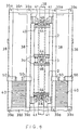
- Fig. 4 is a front view showing a main part of a linear motor elevator according to still another embodiment of this invention. It shows the case where rollers 46 are added between the pair of stators 2, in comparison with the counterweight shown in Fig. 1.
- roller bearings 44 shown in Fig. 8 are arranged hanging down symmetrically and radially from end plate 3a of upper stator 2.
- each roller 46 is freely rotatably supported and is pressed against cylindrical pillar 28.
- the linear motor elevator can be operated the same as that of Fig. 1.
- flexing of the cylindrical pillar 28 can be further reduced in comparison with the case of the counterweight shown in Fig. 1.
- Fig. 5 is a front view showing a main part of a linear motor elevator according to a further embodiment of this invention, and is a view corresponding to Fig. 2.
- Fig. 5 three of the stators 2 assembled in Fig. 4 are linked together.
- Fig. 5 shows the case where the stators are applied to an elevator that requires a propulsive force of 1.5 times that needed for the counterweight shown in Fig. 4.
- Fig. 6 is a front view showing a main part of a linear motor elevator according to another embodiment of this invention. This is an example in which flexing of cylindrical pillar 28 within the stators having an increased linkage length is prevented by the addition of rollers 46 between stator 2A and stator 2 of the counterweight shown in Fig. 3.
- stators of only a few different types of lengths can cope with cages of many different ratings, by linking stators of different length and inserting rollers at this linkage part.
- the prescribed propulsive characteristic can therefore be obtained without difficulty.
- rollers are arranged at the bottom of upper and intermediate stator. But this invention is not limited to these embodiments. Rollers may be arranged at the top of lower and intermediate stator.
- the assembly of the stators on the uprights can be carried out with a higher precision than the prior art.
- rollers for maintaining the gap between the inside face of the stators and the secondary conductor pillar are provided between the stators.
- the difference between the actual gap between the secondary conductor pillar and the stator and the predetermined value can be reduced.
Landscapes
- Engineering & Computer Science (AREA)
- Civil Engineering (AREA)
- Mechanical Engineering (AREA)
- Structural Engineering (AREA)
- Types And Forms Of Lifts (AREA)
- Cage And Drive Apparatuses For Elevators (AREA)
Applications Claiming Priority (2)
| Application Number | Priority Date | Filing Date | Title |
|---|---|---|---|
| JP8282894A JPH07285758A (ja) | 1994-04-21 | 1994-04-21 | リニアモータエレベータ |
| JP82828/94 | 1994-04-21 |
Publications (2)
| Publication Number | Publication Date |
|---|---|
| EP0678471A2 true EP0678471A2 (fr) | 1995-10-25 |
| EP0678471A3 EP0678471A3 (fr) | 1996-02-14 |
Family
ID=13785266
Family Applications (1)
| Application Number | Title | Priority Date | Filing Date |
|---|---|---|---|
| EP95302589A Withdrawn EP0678471A3 (fr) | 1994-04-21 | 1995-04-19 | Ascenseur à moteur linéaire. |
Country Status (2)
| Country | Link |
|---|---|
| EP (1) | EP0678471A3 (fr) |
| JP (1) | JPH07285758A (fr) |
Family Cites Families (5)
| Publication number | Priority date | Publication date | Assignee | Title |
|---|---|---|---|---|
| GB1150174A (en) * | 1966-09-29 | 1969-04-30 | Morris Ltd Herbert | Improvements in an Overhead Travelling Crane or Lift Driven by a Linear Induction Motor. |
| FR2491045A1 (fr) * | 1980-09-30 | 1982-04-02 | Otis Elevator Co | Ascenseur automoteur utilisant comme contrepoids un moteur electrique lineaire |
| JP2659582B2 (ja) * | 1989-02-28 | 1997-09-30 | オーチス エレベータ カンパニー | 円筒型リニアモータのエアギャップ調整装置 |
| JPH04255455A (ja) * | 1991-02-05 | 1992-09-10 | Nippon Otis Elevator Co | リニアモータ |
| US5203430A (en) * | 1991-10-17 | 1993-04-20 | Otis Elevator Company | Elevator flat linear motor secondary |
-
1994
- 1994-04-21 JP JP8282894A patent/JPH07285758A/ja active Pending
-
1995
- 1995-04-19 EP EP95302589A patent/EP0678471A3/fr not_active Withdrawn
Also Published As
| Publication number | Publication date |
|---|---|
| JPH07285758A (ja) | 1995-10-31 |
| EP0678471A3 (fr) | 1996-02-14 |
Similar Documents
| Publication | Publication Date | Title |
|---|---|---|
| US5183980A (en) | Linear motor elevator device with a null-flux position adjustment | |
| US5566785A (en) | Elevator drive machine placed in the counterweight | |
| KR100208425B1 (ko) | 엘리베이터 장치 | |
| US5086881A (en) | Elevator driven by a flat linear motor | |
| KR20070006648A (ko) | 승강 시설용 구동 엔진 및 구동 엔진 설치 방법 | |
| JP2501392B2 (ja) | エレベ―タ | |
| JPH07137964A (ja) | カウンタウエイトに配置したエレベータ駆動装置 | |
| US7165653B2 (en) | Elevator gearless traction machine construction | |
| US5226507A (en) | Roping method of an elevator | |
| EP0678471A2 (fr) | Ascenseur à moteur linéaire | |
| CN117255766A (zh) | 用于构造电梯的方法以及这样的电梯 | |
| GB2281664A (en) | Linear motor and elevator and conveyer using same | |
| JPH05207726A (ja) | リニアモータ | |
| JPH08324924A (ja) | リニアモータエレベータ | |
| WO2002027901A1 (fr) | Moteur lineaire pour ascenseur | |
| EP0385254A1 (fr) | Dispositif d'entrefer pour moteur linéaire toroidal | |
| US11349366B2 (en) | Winding overhang | |
| JPH0881158A (ja) | エレベータ用円筒形リニヤモータ | |
| CN221876271U (zh) | 电梯对重装置以及电梯 | |
| KR102076420B1 (ko) | 엘리베이터용 리니어 모터 | |
| JP2934924B2 (ja) | エレベーター主ロープ保持装置 | |
| EP1947049A1 (fr) | Construction d'une machine de traction sans boîte de vitesse de profondeur | |
| CN100393601C (zh) | 电梯装置 | |
| JP7559251B2 (ja) | 昇降路上部構造体、昇降路上部構造体の設置方法、及び、エレベーター | |
| US7874404B1 (en) | Elevator system having drive motor located between elevator car and hoistway sidewall |
Legal Events
| Date | Code | Title | Description |
|---|---|---|---|
| PUAI | Public reference made under article 153(3) epc to a published international application that has entered the european phase |
Free format text: ORIGINAL CODE: 0009012 |
|
| 17P | Request for examination filed |
Effective date: 19950502 |
|
| AK | Designated contracting states |
Kind code of ref document: A2 Designated state(s): DE FR GB |
|
| PUAL | Search report despatched |
Free format text: ORIGINAL CODE: 0009013 |
|
| AK | Designated contracting states |
Kind code of ref document: A3 Designated state(s): DE FR GB |
|
| 17Q | First examination report despatched |
Effective date: 19991112 |
|
| STAA | Information on the status of an ep patent application or granted ep patent |
Free format text: STATUS: THE APPLICATION IS DEEMED TO BE WITHDRAWN |
|
| 18D | Application deemed to be withdrawn |
Effective date: 20000323 |