EP0678648A1 - Schliessvorrichtung - Google Patents
Schliessvorrichtung Download PDFInfo
- Publication number
- EP0678648A1 EP0678648A1 EP95302657A EP95302657A EP0678648A1 EP 0678648 A1 EP0678648 A1 EP 0678648A1 EP 95302657 A EP95302657 A EP 95302657A EP 95302657 A EP95302657 A EP 95302657A EP 0678648 A1 EP0678648 A1 EP 0678648A1
- Authority
- EP
- European Patent Office
- Prior art keywords
- slat
- arrangement according
- formation
- projection
- relative movement
- Prior art date
- Legal status (The legal status is an assumption and is not a legal conclusion. Google has not performed a legal analysis and makes no representation as to the accuracy of the status listed.)
- Withdrawn
Links
- 230000015572 biosynthetic process Effects 0.000 claims abstract description 58
- 239000000463 material Substances 0.000 claims description 13
- 230000000717 retained effect Effects 0.000 claims description 4
- 230000000295 complement effect Effects 0.000 claims description 3
- 230000001419 dependent effect Effects 0.000 claims 2
- 241001417494 Sciaenidae Species 0.000 abstract description 12
- 238000001125 extrusion Methods 0.000 abstract description 4
- 238000005755 formation reaction Methods 0.000 description 37
- 238000004080 punching Methods 0.000 description 3
- 238000010276 construction Methods 0.000 description 2
- 238000000034 method Methods 0.000 description 2
- 238000003825 pressing Methods 0.000 description 2
- 239000000853 adhesive Substances 0.000 description 1
- 230000001070 adhesive effect Effects 0.000 description 1
- 239000002390 adhesive tape Substances 0.000 description 1
- 238000005452 bending Methods 0.000 description 1
- 238000005520 cutting process Methods 0.000 description 1
- 238000009434 installation Methods 0.000 description 1
- 238000004519 manufacturing process Methods 0.000 description 1
- 239000002184 metal Substances 0.000 description 1
- 238000012986 modification Methods 0.000 description 1
- 230000004048 modification Effects 0.000 description 1
- 229920003023 plastic Polymers 0.000 description 1
- 239000004033 plastic Substances 0.000 description 1
- 238000003860 storage Methods 0.000 description 1
Images



Classifications
-
- E—FIXED CONSTRUCTIONS
- E06—DOORS, WINDOWS, SHUTTERS, OR ROLLER BLINDS IN GENERAL; LADDERS
- E06B—FIXED OR MOVABLE CLOSURES FOR OPENINGS IN BUILDINGS, VEHICLES, FENCES OR LIKE ENCLOSURES IN GENERAL, e.g. DOORS, WINDOWS, BLINDS, GATES
- E06B9/00—Screening or protective devices for wall or similar openings, with or without operating or securing mechanisms; Closures of similar construction
- E06B9/02—Shutters, movable grilles, or other safety closing devices, e.g. against burglary
- E06B9/08—Roll-type closures
- E06B9/11—Roller shutters
- E06B9/15—Roller shutters with closing members formed of slats or the like
-
- E—FIXED CONSTRUCTIONS
- E06—DOORS, WINDOWS, SHUTTERS, OR ROLLER BLINDS IN GENERAL; LADDERS
- E06B—FIXED OR MOVABLE CLOSURES FOR OPENINGS IN BUILDINGS, VEHICLES, FENCES OR LIKE ENCLOSURES IN GENERAL, e.g. DOORS, WINDOWS, BLINDS, GATES
- E06B9/00—Screening or protective devices for wall or similar openings, with or without operating or securing mechanisms; Closures of similar construction
- E06B9/02—Shutters, movable grilles, or other safety closing devices, e.g. against burglary
- E06B9/08—Roll-type closures
- E06B9/11—Roller shutters
- E06B9/115—Roller shutters specially adapted for furniture
Definitions
- the present invention relates to closure arrangements, such as doors and shutters, and particularly, but not exclusively to tambour doors.
- a tambour door consists of a plurality of slats which are arranged alongside each other. Each slat is connected in a hinged manner to both adjacent slats. The slats can be arranged to form a substantially planar door. The hinged connections also allow the door to be rolled. In a common arrangement, a roller is located horizontally across the top of a doorway or other opening, or vertically to one side of the opening, and the tambour door is rolled onto the roller in order to open the door or rolled off the roller to close the opening. Tambour doors of this general form are widely used for various types of office furniture, such as filing cabinets and storage cupboards, and similar arrangements are used for other purposes, such as blinds and security shutters.
- Adhesive can transfer to the front face of the door, where it attracts dirt and becomes unsightly.
- a closure arrangement comprising a plurality of slat members hingedly connected together to form a closure member which may move between a closed condition, in which the slats form a closure member which closes an opening, and an open condition to which the closure member may move by virtue of the hinged connections, the slats being retained substantially contiguous and at least one slat member comprising at least one formation which may engage an adjacent slat member to prevent or limit relative movement of adjacent slat members generally parallel to the length of the slat members, and wherein the or each formation is so formed as to prevent or limit relative movement in either sense.
- Each slat member may comprise a first hinge portion and a second hinge portion able to engage a first hinge portion of a like slat member to provide a hinged connection therebetween.
- the first or second hinge portions is preferably modified at least at one position to provide an engaging formation as aforesaid.
- the other hinge portion is preferably modified to provide a complementary formation for receiving the or each engaging formation.
- Each first hinge portion may comprise an elongate channel portion and each second hinge portion may comprise an elongate portion which is received, in use, in the channel portion of another slat member to provide a hinged connection by rotation of the elongate portion in the channel portion.
- One or both of the hinge portions may be modified at least at one position to provide an engaging formation.
- a wall portion of the channel portion may project into the channel to provide the engaging formation.
- a portion of the second hinge portion may be removed to form a recess for receiving the engaging formation.
- one or both of the channel portion and the elongate portion extend along substantially the whole length of the slat member.
- the or each engaging formation may be formed by deforming part of the material of the slat member to form the formation in a slat member.
- Each slat member may comprise at least one cut-out for receiving an engaging formation.
- each slat member comprises at least one formation as aforesaid.
- at least one formation comprises a projection engageable with another slat member.
- the projection may have a first region engageable with another slat member at a first location to prevent or limit relative movement in a first sense, and a second region engageable with the other slat member at a second location to prevent or limit relative movement in a second sense.
- the projection preferably has first and second faces providing the said first and second regions.
- each slat member comprises a recess for receiving a projection as aforesaid, wherein relative movement is prevented or limited by abutment of the projection with the recess walls.
- the slat members are so formed that the or each engaging formation is substantially not visible from said front face.
- the invention provides a closure arrangement comprising a plurality of slat members hingedly connected together to form a closure member which may move between a closed condition, in which the slats form a closure member which closes an opening and has a front face, and an open condition to which the closure member may move by virtue of the hinged connections, the slat members being retained contiguous and at least one slat member comprising at least one formation which may engage an adjacent slat member to prevent or limit relative movement of adjacent slat members generally parallel to the length of the slat members, and wherein the slat members are so formed that the or each engaging formation is not visible from the said front face, preferably when the closure member is in the closed condition.
- Each slat member may comprise a first hinge portion and a second hinge portion able to engage a first hinge portion of a like slat member to provide a hinged connection therebetween.
- the first or second hinge portions is preferably modified at least at one position to provide an engaging formation as aforesaid.
- the other hinge portion is preferably modified to provide a complementary formation for receiving the or each engaging formation.
- Each first hinge portion may comprise an elongate channel portion and each second hinge portion may comprise an elongate portion which is received, in use, in the channel portion of another slat member to provide a hinged connection by rotation of the elongate portion in the channel portion.
- One or both of the hinge portions is preferably modified at least at one position to provide the said engaging formations.
- a wall portion of the channel portion may project into the channel to provide the engaging formation.
- a portion of the second hinge portion may be removed to form a recess for receiving the engaging formation.
- One or both of the channel portion and the elongate portion preferably extend along substantially the whole length of the slat member.
- the or each engaging formation may be formed by deforming part of the material of the slat member to form the formation in a slat member.
- Each slat member may comprise at least one cut-out for receiving an engaging formation.
- each slat member comprises at least one formation as aforesaid.
- the slat members may provide a substantially continuous front face when the closure member is in the closed condition.
- At least one formation preferably comprises a projection engageable with another slat member.
- the formation is preferably located wholly behind the front face.
- the formation may project from the rear face towards the front face.
- the formation may be formed by deforming part of the material of the slat, preferably of the rear face of a slat member.
- Each slat member preferably comprises a recess for receiving a projection as aforesaid, wherein relative movement is prevented or limited by abutment of the projection with the recess walls.
- the or each formation may be so formed as to prevent or limit relative movement in either sense.
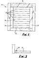
- Fig. 1 shows a tambour door arrangement 10.
- the arrangement 10 comprises a plurality of slat members 12 hingedly connected together to form a door 14 which may slide between a closed condition (shown in Fig. 1), in which the slats form a door 14 closing an opening 16, and an open condition in which the door adopts a rolled condition around a roller 18, by virtue of the hinged connections.
- Each slat is an identical length of extruded material, preferably synthetic plastics material. Other materials, such as metal, could be used, and techniques other than extrusion could be used to form the slats.
- the slats 12 each have a box section central region 20 and male and female edge regions 22,24 which can fit together to provide a hinged connection.
- the central region 20 has two cavities 26 in the example shown.
- the male edge 22 consists of a circular cylindrical head 28 parallel to the length of the extrusion, and attached to the central region 20 by means of an arm 30.
- a circular cylindrical sleeve 32 is formed and is sufficiently large to receive the head 28 of an adjacent slat 12.
- the mouth 34 of the sleeve 32 is sufficiently wide to allow at least limited hinging movement of one slat relative to another when the head 28 of the one slat is fitted in the sleeve 32 of the other, to be rotatable therein.
- Fig. 2 shows three slats connected at two joints 36,38.
- the upper and middle slats are aligned so that the front faces 40 of the slats form a substantially continuous front face to the door.
- the continuous nature of the front face is further enhanced by the presence of a lip 42 at the female edge 24.
- the head 28 has rotated in the sleeve 32 so that the lowest slat 12 has rotated relative to the middle slat and is close to the other extreme position. It can be seen that the front face 40 of the door has now been broken but that the articulation would allow a door formed of many slats to be wound onto a roller of sufficiently large radius.
- the slats remain substantially contiguous. That is, there are substantially no gaps between them. This, and the continuous nature of the sleeves 32 and heads 28 along substantially the whole length of the slats ensures that slats cannot be separated to allow access or viewing through the closure member. This represents an important security feature in many applications.
- a roller 18 would normally be mounted horizontally above the door 14 (as shown), or vertically to one side of the opening.
- the door 14 can then be rolled onto the roller 18 to open the door, or pulled from the roller 18 to close the door. Movement of the door is assisted by guide channels 44 placed vertically at the sides of the opening 16, as shown schematically in Fig. 3.
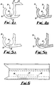
- each slat 12 has at least one formation 46 (Figs. 4A,4B etc.) which may engage an adjacent slat 12 to prevent or limit movement of adjacent slats generally parallel to the length of the slats.
- Each formation is formed to prevent or limit relative movement in either sense, as will be described.
- the formation 46 is a projection formed by pressing or punching the material of the wall of the sleeve 32, at one or locations along the slat. This deforms the wall to form the projection.
- Figs. 4A and 4B show one alternative for forming the projection 46 by breaking the material of the sleeve 32 along part of its length, and bending a leaf of material to project into the channel. This leaf of material can be attached to the slat 12 at either edge, according to how it is formed, and these two alternatives are shown in Figs. 4A,4B and 5A,5B.
- Figs. 4A and 5A are end elevations of the sleeve 32 showing an end face 48 of the projection 46.
- Figs. 4B and 5B are sections at the projection 46.
- Fig. 6 is a side view of the sleeve 32 showing the length of the projection 46. It is to be noted that the projection 46 does not extend the whole way along the sleeve and that it has two end faces 48. It is also to be noted that in most situations, the slat will be very much longer than the projection 46, so that the length of the projection 46 and its position along the slat can be selected to ensure it is adequately strong for the intended application, taking into account the material used and the forces expected, but without being limited by the length of the slat. Using a projection with two oppositely-directed end faces allows relative movement in either direction to be prevented by a single projection. Thus, the projection is of virtually arbitrary length and can be virtually arbitrarily located.
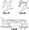
- the male edge 22 (Figs. 7A,7B,8) is adapted to receive the projection 46 by cutting away part of the head 28 to leave a recess 50.
- the length of the recess 50 (parallel to the main length of the slat 12) is chosen to be slightly longer than the corresponding length of the projection 46.
- the two end faces 52 of the recess 50 provide surfaces for abutment of the end faces 48, as will be described.
- Figs. 9A and 98 correspond to the views of Figs. 4A,4B respectively, but show a hinge formed by inter-connecting the edges 22,24 of adjacent slats 12. It can be seen from Figs. 9A,9B that the projection 46 is received in the recess 50. Since the recess 50 is slightly longer than the projection 46, there will be slight clearance between the corresponding end faces 48,52 but abutment of these end faces at one or other end of the recess 50 will limit relative movement of the slats 12.
- each slat In order for the hinge shown in Figs. 9A and 9B to be formed, it is necessary to provide each slat with a projection 46 and recess 50 at the same locations along their lengths, so that any pair of slats 12 can be mated with the projection 46 of one engaging the recess 50 of the other.
- the projection 46 projects forward from the rear face of the slat, towards the front face, it is expected that it can be readily formed by a punching or pressing operation.
- the strength of the engagement between adjacent slats can be improved by increasing the length of the projections 46 (and the recesses 50) or by forming additional projections and recesses at other locations along the slats.
- FIGS. 10 and 11 show a projection 54 formed by punching a short length of the wall of the sleeve 32 through into the interior of the sleeve, close to one end 56 of the slat 12. This exposes a face 58 within the sleeve 32.
- Figs. 12 and 13 show that a length of the head 28 at the end 56 is cut away to leave a gap 60 and an abutment face 62.
- the gap 60 can receive the projection 54 when the hinge is assembled as indicated in Figs. 14 and 15. It can be seen from these views that the gap 60 is slightly over length relative to the projection 54, providing clearance at 64, so that a little play is available, but abutment of the faces 58,62 limits relative movement of the slats.
- each slat would be formed as a mirror image of the forms shown in Figs. 10 to 15, so that at each end of the slat, there is a formation limiting relative move in one sense, but neither being visible from the front face of the door.
Landscapes
- Engineering & Computer Science (AREA)
- Structural Engineering (AREA)
- Architecture (AREA)
- Civil Engineering (AREA)
- Operating, Guiding And Securing Of Roll- Type Closing Members (AREA)
Applications Claiming Priority (2)
| Application Number | Priority Date | Filing Date | Title |
|---|---|---|---|
| GB9408072A GB9408072D0 (en) | 1994-04-22 | 1994-04-22 | Closure arrangement |
| GB9408072 | 1994-04-22 |
Publications (1)
| Publication Number | Publication Date |
|---|---|
| EP0678648A1 true EP0678648A1 (de) | 1995-10-25 |
Family
ID=10754005
Family Applications (1)
| Application Number | Title | Priority Date | Filing Date |
|---|---|---|---|
| EP95302657A Withdrawn EP0678648A1 (de) | 1994-04-22 | 1995-04-21 | Schliessvorrichtung |
Country Status (2)
| Country | Link |
|---|---|
| EP (1) | EP0678648A1 (de) |
| GB (2) | GB9408072D0 (de) |
Cited By (2)
| Publication number | Priority date | Publication date | Assignee | Title |
|---|---|---|---|---|
| EP2039871A1 (de) * | 2007-09-20 | 2009-03-25 | Peter Bichler | Rolladen und Glied dafür |
| FR3136806A1 (fr) * | 2022-06-20 | 2023-12-22 | Faurecia Interieur Industrie | Rideau de fermeture d’un réceptacle comprenant des éléments rigides articulés |
Families Citing this family (1)
| Publication number | Priority date | Publication date | Assignee | Title |
|---|---|---|---|---|
| GB2311797A (en) * | 1996-03-30 | 1997-10-08 | Webb Ronald R | Preventing longitudinal movement between adjacent slats of a roller shutter |
Citations (4)
| Publication number | Priority date | Publication date | Assignee | Title |
|---|---|---|---|---|
| BE637053A (de) * | ||||
| DE338382C (de) * | 1920-01-28 | 1921-06-18 | Ernst Wohlfahrt | Rolladen aus falzartig an den Laengskanten ineinandergreifenden Metallschienen |
| GB894260A (en) * | 1959-06-30 | 1962-04-18 | Henri Martinage | Improvements in or relating to roller shutters made of plastic or metal |
| DE8702763U1 (de) * | 1987-02-24 | 1987-09-03 | Hetal-Werke Franz Hettich Gmbh & Co, 7297 Alpirsbach | Verschiebsicherung von Rolladen-Profilstäben |
Family Cites Families (6)
| Publication number | Priority date | Publication date | Assignee | Title |
|---|---|---|---|---|
| GB265873A (en) * | 1926-09-04 | 1927-02-17 | Tomitaro Sudzki | Improvement in fire-proof shutters |
| GB875884A (en) * | 1958-12-15 | 1961-08-23 | Mueller Hermann | Lattice blinds for windows, doors or the like |
| GB921987A (en) * | 1960-10-17 | 1963-03-27 | Meyers Taylor Pty Ltd | Improvements in slat assemblies for awnings, screens, blinds, doors or the like |
| GR69905B (de) * | 1979-10-31 | 1982-07-20 | Steineberg Kurt | |
| GB2141471B (en) * | 1983-04-21 | 1986-07-02 | De La Rue Syst | Injection moulded slat for a shutter |
| GB2188967A (en) * | 1986-03-26 | 1987-10-14 | Rotalac Plastics | Slatted shutters |
-
1994
- 1994-04-22 GB GB9408072A patent/GB9408072D0/en active Pending
-
1995
- 1995-04-21 GB GB9508176A patent/GB2288626A/en not_active Withdrawn
- 1995-04-21 EP EP95302657A patent/EP0678648A1/de not_active Withdrawn
Patent Citations (4)
| Publication number | Priority date | Publication date | Assignee | Title |
|---|---|---|---|---|
| BE637053A (de) * | ||||
| DE338382C (de) * | 1920-01-28 | 1921-06-18 | Ernst Wohlfahrt | Rolladen aus falzartig an den Laengskanten ineinandergreifenden Metallschienen |
| GB894260A (en) * | 1959-06-30 | 1962-04-18 | Henri Martinage | Improvements in or relating to roller shutters made of plastic or metal |
| DE8702763U1 (de) * | 1987-02-24 | 1987-09-03 | Hetal-Werke Franz Hettich Gmbh & Co, 7297 Alpirsbach | Verschiebsicherung von Rolladen-Profilstäben |
Cited By (2)
| Publication number | Priority date | Publication date | Assignee | Title |
|---|---|---|---|---|
| EP2039871A1 (de) * | 2007-09-20 | 2009-03-25 | Peter Bichler | Rolladen und Glied dafür |
| FR3136806A1 (fr) * | 2022-06-20 | 2023-12-22 | Faurecia Interieur Industrie | Rideau de fermeture d’un réceptacle comprenant des éléments rigides articulés |
Also Published As
| Publication number | Publication date |
|---|---|
| GB9408072D0 (en) | 1994-06-15 |
| GB9508176D0 (en) | 1995-06-07 |
| GB2288626A (en) | 1995-10-25 |
Similar Documents
| Publication | Publication Date | Title |
|---|---|---|
| US6129130A (en) | Door edge debris block and air seal | |
| US6328091B1 (en) | Upward acting sectional door with pinch resistant edge profile between door panels | |
| US4631894A (en) | Hardware for panel doors | |
| NZ242269A (en) | Door and frame smoke seal with integral casing and seal member | |
| IE52236B1 (en) | Adjustable door jamb assembly | |
| EP0121307B1 (de) | Halterung für die Kopfschiene einer Lamellenjalousie | |
| US4846247A (en) | Silent tambour slats | |
| EP0233021B1 (de) | Drehzapfenlagerblock für Falttüren | |
| US8191603B1 (en) | Accordion-type transparent segmented shutter and shutter assembly | |
| GB2288626A (en) | Slatted closure | |
| EP3500717A1 (de) | Anordnung aus einer tür- und türrahmen mit geringerem risiko von quetschverletzungen | |
| JPH02171488A (ja) | カーテン用スラット及びスラット式カーテン | |
| WO2018034572A1 (en) | Assembly of door and door frame with reduced risk of squeeze caused injuries | |
| US20110120021A1 (en) | Door Assembly | |
| BE1014653A5 (nl) | Verbeterde schuifdeur. | |
| EP0735226A2 (de) | Platte zur Herstellung von, aus mehreren Platten bestehenden, Schiebefalttüren | |
| US6997230B2 (en) | Folding device as room divider or room closure | |
| WO1995025868A1 (en) | Articulated joint means | |
| EP3670821B1 (de) | Einsatz für eine architektonische öffnung | |
| EP0661185A1 (de) | Verbesserungen an Sicherheitsvorrichtungen bei flügelartigen Bewegungselementen | |
| HU227749B1 (hu) | Feltekerhetõ redõny | |
| CA2210018A1 (en) | Rolling door made from interlocking thermoplastic panels | |
| AU678115B2 (en) | Security device for a sliding member | |
| DE60108935T2 (de) | Profillamelle für einen Verschlussvorhang | |
| KR102703893B1 (ko) | 손끼임 방지 안전장치 |
Legal Events
| Date | Code | Title | Description |
|---|---|---|---|
| PUAI | Public reference made under article 153(3) epc to a published international application that has entered the european phase |
Free format text: ORIGINAL CODE: 0009012 |
|
| AK | Designated contracting states |
Kind code of ref document: A1 Designated state(s): DE ES FR GB IT NL |
|
| 17P | Request for examination filed |
Effective date: 19960417 |
|
| 17Q | First examination report despatched |
Effective date: 19970522 |
|
| STAA | Information on the status of an ep patent application or granted ep patent |
Free format text: STATUS: THE APPLICATION IS DEEMED TO BE WITHDRAWN |
|
| 18D | Application deemed to be withdrawn |
Effective date: 19971002 |