EP0678705A2 - Dispositif d'irradiation - Google Patents
Dispositif d'irradiation Download PDFInfo
- Publication number
- EP0678705A2 EP0678705A2 EP95105863A EP95105863A EP0678705A2 EP 0678705 A2 EP0678705 A2 EP 0678705A2 EP 95105863 A EP95105863 A EP 95105863A EP 95105863 A EP95105863 A EP 95105863A EP 0678705 A2 EP0678705 A2 EP 0678705A2
- Authority
- EP
- European Patent Office
- Prior art keywords
- frame
- filter
- irradiation device
- cavity
- annular chamber
- Prior art date
- Legal status (The legal status is an assumption and is not a legal conclusion. Google has not performed a legal analysis and makes no representation as to the accuracy of the status listed.)
- Granted
Links
- 230000005855 radiation Effects 0.000 claims abstract description 25
- 238000001228 spectrum Methods 0.000 claims abstract description 6
- 239000003779 heat-resistant material Substances 0.000 claims abstract description 5
- 239000011521 glass Substances 0.000 claims abstract description 4
- 229910052500 inorganic mineral Inorganic materials 0.000 claims abstract description 4
- 239000011707 mineral Substances 0.000 claims abstract description 4
- 239000004033 plastic Substances 0.000 claims abstract description 4
- 229920003023 plastic Polymers 0.000 claims abstract description 4
- 239000004417 polycarbonate Substances 0.000 claims abstract description 4
- 229920000515 polycarbonate Polymers 0.000 claims abstract description 4
- 238000001816 cooling Methods 0.000 claims description 11
- 238000010438 heat treatment Methods 0.000 claims description 6
- 239000012528 membrane Substances 0.000 claims description 5
- 238000009825 accumulation Methods 0.000 claims description 4
- 239000004020 conductor Substances 0.000 claims description 3
- 230000002093 peripheral effect Effects 0.000 claims description 3
- 238000000015 thermotherapy Methods 0.000 abstract description 4
- 239000007788 liquid Substances 0.000 abstract 1
- 230000000694 effects Effects 0.000 description 4
- 238000007789 sealing Methods 0.000 description 4
- 230000035508 accumulation Effects 0.000 description 3
- 230000006835 compression Effects 0.000 description 2
- 238000007906 compression Methods 0.000 description 2
- 239000000463 material Substances 0.000 description 2
- XLYOFNOQVPJJNP-UHFFFAOYSA-N water Substances O XLYOFNOQVPJJNP-UHFFFAOYSA-N 0.000 description 2
- 241000283690 Bos taurus Species 0.000 description 1
- XAGFODPZIPBFFR-UHFFFAOYSA-N aluminium Chemical compound [Al] XAGFODPZIPBFFR-UHFFFAOYSA-N 0.000 description 1
- 229910052782 aluminium Inorganic materials 0.000 description 1
- 238000009835 boiling Methods 0.000 description 1
- 238000009792 diffusion process Methods 0.000 description 1
- 239000000417 fungicide Substances 0.000 description 1
- 239000002241 glass-ceramic Substances 0.000 description 1
- 230000017525 heat dissipation Effects 0.000 description 1
- 238000005304 joining Methods 0.000 description 1
- 239000010410 layer Substances 0.000 description 1
- 238000004519 manufacturing process Methods 0.000 description 1
- 238000000034 method Methods 0.000 description 1
- 229920002492 poly(sulfone) Polymers 0.000 description 1
- 238000003825 pressing Methods 0.000 description 1
- 239000013464 silicone adhesive Substances 0.000 description 1
Images


Classifications
-
- F—MECHANICAL ENGINEERING; LIGHTING; HEATING; WEAPONS; BLASTING
- F21—LIGHTING
- F21V—FUNCTIONAL FEATURES OR DETAILS OF LIGHTING DEVICES OR SYSTEMS THEREOF; STRUCTURAL COMBINATIONS OF LIGHTING DEVICES WITH OTHER ARTICLES, NOT OTHERWISE PROVIDED FOR
- F21V29/00—Protecting lighting devices from thermal damage; Cooling or heating arrangements specially adapted for lighting devices or systems
- F21V29/50—Cooling arrangements
- F21V29/70—Cooling arrangements characterised by passive heat-dissipating elements, e.g. heat-sinks
- F21V29/74—Cooling arrangements characterised by passive heat-dissipating elements, e.g. heat-sinks with fins or blades
-
- A—HUMAN NECESSITIES
- A61—MEDICAL OR VETERINARY SCIENCE; HYGIENE
- A61N—ELECTROTHERAPY; MAGNETOTHERAPY; RADIATION THERAPY; ULTRASOUND THERAPY
- A61N5/00—Radiation therapy
- A61N5/06—Radiation therapy using light
-
- F—MECHANICAL ENGINEERING; LIGHTING; HEATING; WEAPONS; BLASTING
- F21—LIGHTING
- F21V—FUNCTIONAL FEATURES OR DETAILS OF LIGHTING DEVICES OR SYSTEMS THEREOF; STRUCTURAL COMBINATIONS OF LIGHTING DEVICES WITH OTHER ARTICLES, NOT OTHERWISE PROVIDED FOR
- F21V31/00—Gas-tight or water-tight arrangements
- F21V31/03—Gas-tight or water-tight arrangements with provision for venting
-
- F—MECHANICAL ENGINEERING; LIGHTING; HEATING; WEAPONS; BLASTING
- F21—LIGHTING
- F21V—FUNCTIONAL FEATURES OR DETAILS OF LIGHTING DEVICES OR SYSTEMS THEREOF; STRUCTURAL COMBINATIONS OF LIGHTING DEVICES WITH OTHER ARTICLES, NOT OTHERWISE PROVIDED FOR
- F21V9/00—Elements for modifying spectral properties, polarisation or intensity of the light emitted, e.g. filters
- F21V9/08—Elements for modifying spectral properties, polarisation or intensity of the light emitted, e.g. filters for producing coloured light, e.g. monochromatic; for reducing intensity of light
- F21V9/12—Elements for modifying spectral properties, polarisation or intensity of the light emitted, e.g. filters for producing coloured light, e.g. monochromatic; for reducing intensity of light with liquid-filled chambers
-
- A—HUMAN NECESSITIES
- A61—MEDICAL OR VETERINARY SCIENCE; HYGIENE
- A61N—ELECTROTHERAPY; MAGNETOTHERAPY; RADIATION THERAPY; ULTRASOUND THERAPY
- A61N5/00—Radiation therapy
- A61N5/06—Radiation therapy using light
- A61N2005/0664—Details
- A61N2005/0667—Filters
Definitions
- the invention relates to an irradiation device with a radiation source and a filter arranged in the beam path, which has two transparent, essentially plane-parallel arranged disks, which are held with their peripheral edges in a frame made of a good heat-conducting material, the disks and the frame define a closed cavity in which a medium which selectively influences the radiation spectrum is provided.
- Such an irradiation device is known for example from EP-A-0311898.
- the radiation device described in this publication is used for heat therapy, in particular of the human body.
- the purpose of the filter used in this device is that the radiation spectrum emitted by the radiation source in its entirety is suitable for heat therapy to a limited extent. For this reason, certain bands are filtered out of the radiation spectrum by the filter.
- the known filter consists of a multi-part frame, which is constructed from an outer frame, which is connected to the housing of the radiation device, and an interchangeable frame arranged therein, which carries both filter disks.
- Two press rings are arranged on the interchangeable frame, which ensure that the two filter disks are each pressed onto their seals in the direction of the cavity. At least one of the press rings is not releasably connected to the change frame by a flanging process.
- the object of the present invention is to improve an irradiation device of the type mentioned in the introduction so that the filter can have a simpler structure.
- the frame is divided essentially transversely to the filter axis into a first and a second half of the frame such that one disc is arranged on the side facing the cavity on the first half of the frame and the other disc on the cavity facing side is arranged on the second frame half. Due to this division in two, the frame halves themselves now ensure an accurate and stable arrangement of the filter disks without additional pressing rings being required. Furthermore, the two frame halves can be arranged to one another by releasable connecting means, so that access to the medium located in the cavity and the filter disks is granted even after some operating time.
- At least one of the disks is inserted in a substantially precise fit in a circumferential step of the first and second frame halves.
- the step provides a stop shoulder for the disk so that it cannot be pressed out of its holder by the pressure prevailing in the cavity.
- the sealing effect of this filter can be increased in particular by the fact that the disks each abut against an essentially circumferential seal at their edge on the side facing away from the cavity. Contrary to the prior art, the pressure inside the cavity in this arrangement ensures that the sealing effect increases as the pressure increases, since the disks are pressed ever more firmly onto their seals.
- a circumferential one connected to the cavity can be connected in at least one of the frame halves
- Annular chamber can be arranged, whereby the heat can be removed more quickly through the frame housing, due to the increased contact area between the medium and the frame. It is particularly advantageous if an annular chamber half is arranged in each of the two frame halves to form a common large annular chamber. By joining the two frame halves, a relatively large annular chamber is created in which a very good heat exchange between the frame and the medium can take place.
- At least one circumferential seal can be arranged outside the annular chamber in one frame half, which abuts the other frame half.
- a pressure compensation device can be provided in or on one of the annular chambers, which compensates for pressure fluctuations due to the heating of the medium in the cavity, and also absorbs any accumulation of gas bubbles. The pressure compensation device thus ensures that the disks cannot be deformed by the internal pressure in the hollow chamber.
- the pressure compensation device consists of a compensation container which is connected to an annular chamber and which has a compensation chamber which is delimited at least on one side by a flexible membrane.
- the flexible membrane then diverts in the respective direction when the pressure rises or falls.
- a spring-loaded piston can be arranged in the compensation chamber of the expansion tank be, which compresses or rebounds correspondingly in the case of pressure fluctuations in the cavity.
- this disk can also be made of plastic, preferably polycarbonate. The material costs can thus be greatly reduced.
- the pane facing the radiation source can preferably consist of a heat-resistant material, preferably mineral glass. If the radiation source is not quite as powerful, polysulfone can also be used, otherwise a glass ceramic sold under the name "Robax" is preferred.
- the heat absorbed by the frame can be dissipated to the outside even more quickly if cooling fins are arranged on its outer circumference.
- a simple fastening of the two frame halves to one another can be achieved in that some cooling fins are made thickened and correspondingly have through holes aligned with the first and second frame halves for receiving fastening means.
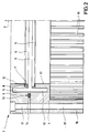
- FIG. 1 and 2 show a filter 1, which can be arranged in the beam path of a radiation source, not shown, of an irradiation device.
- the filter 1 essentially consists of a frame which is divided into two at right angles to the filter axis and consists of a first frame half 3 and a second frame half 4, as well as a filter disk 5 facing away from the radiation source and a second filter disk 6 arranged parallel to it.
- the flat filter disks 5, 6 are used in a circumferential step 7 of the first and second frame halves 3, 4 with a precise fit.
- the filter disks 5, 6 each abut a peripheral seal 8 on their edge on the side facing the bottom of the step 7.
- the seal 8 can consist, for example, of a suitable silicone adhesive layer, so that the filter disks 5, 6 are simultaneously fastened by the seal 8 in the corresponding frame halves 3, 4.
- the stage 7 is arranged in each case in the frame halves 3, 4 in such a way that the two filter disks 5, 6 are arranged at a certain axial distance from one another and thus an intermediate, form disc-shaped cavity 9.
- This cavity 9 is filled with a medium which selectively influences the radiation spectrum in order to filter out certain bands of the radiation emitted by the radiation source.
- this medium usually consists of water, which may also contain fungicides.
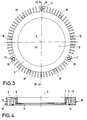
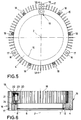
- the two frame halves 3, 4 are each provided with a relatively large through hole 10 which is concentric with the filter axis 2.
- annular chamber halves 11 and 12 which are connected to the cavity 9, are each arranged concentrically to the filter axis 2.
- the cavity 9 is only left open along its outer edge with respect to the cattle chamber halves 11, 12.
- the ring chamber halves 11, 12 each extend as far as possible parallel to the filter axis 2 into the respective frame halves 4, 5.
- the annular chamber halves 11, 12 are preferably introduced into the frame halves 3, 4 in the form of annular recesses.
- the ring chamber halves 11, 12 are also filled with the medium.
- the first frame half 3 has a circumferential annular groove 13, which is arranged opposite the filter axis 2 outside the annular chamber halves 11, 12 and into which a sealing ring 14 is inserted, which is in the parting plane of the first and the second frame half 3, 4 sealingly comes into contact with the second frame half 4.
- cooling fins 15 are arranged on the circumference of the first and second frame halves 3, 4, which increase the surface area and thus the cooling effect light can be designed wavy.
- the cooling fins 15 of the second frame half 4 are substantially longer than the cooling fins 15 of the first frame half 3 and are no longer connected to the main body of the second frame half 4 over a large part of their length.
- enlarged webs 16 are arranged on the outer circumference of the frame halves 3, 4 in the same longitudinal extent as the cooling fins 15.
- the webs 16 serve to receive longitudinal bores 17, into which fasteners (not shown) can be inserted for fastening to the housing (not shown) of the radiation device.
- material accumulations 18 are formed between some cooling fins at regular intervals, which have aligned threaded bores on the first and second frame halves 3, 4, and into the fastening means, also not shown, e.g. Screws for connecting the two frame halves 3, 4 can be inserted.
- the first filter disk 5 does not heat up as much due to the medium in the cavity 9, which is why a less heat-resistant material can also be used.
- the first filter disc 5 is therefore made of plastic, preferably polycarbonate.
- the second filter disk 6, however, is directly exposed to the radiation source and therefore heats up considerably, which is why this disk preferably consists of a heat-resistant material, preferably mineral glass.
- the second frame half 4 has a pressure compensation device 19 which is connected to the annular chamber half 12 and which compensates for pressure fluctuations due to the thermal expansion of the medium in the cavity 9, and picks up any accumulation of gas bubbles.
- the pressure compensation device 19 shown consists of one placed on the second frame half 4 Expansion tank 20, which has a compensation chamber 21 which is closed with a screw cap 22.
- the screw cap 22 has a viewing window, below which a flexible membrane 23 is arranged.
- At the lower end of the expansion tank 20 there is a cylindrical hollow pin 24 which is pressed into a bore in the second frame half 4 or, as shown in FIG.
- the variant of a pressure compensation device according to FIG. 7 has a seal 25 between the compensation container 20 and the second frame half 4, which surrounds the hollow pin 23 provided with an external thread 26.
- FIG. 8 shows a further variant of a pressure compensation device, in which a piston 28, which is loaded on one side by a compression spring 27, is arranged in the compensation chamber 21 of the compensation container 20. So that the medium is only within the area of the compensation chamber 21 which is delimited on one side by the end face 29 of the piston 28, the piston 28 has sealing rings 30 on its circumference which bear against the compensation chamber wall.
- the frame halves 3, 4 are each made of a good heat-conducting material, e.g. Aluminum.
- the radiation source of the irradiation device is switched on, so that it emits beams in the direction of the filter 1.
- These rays first hit the heat-resistant second filter disk 6 and then the Medium 9 located medium, and then on the first filter disc 5.
- the heating of the second filter disc 6 also results in a heating of the medium in the cavity 9. Since the ring chamber halves 11, 12 are in connection with the cavity 9 and because of their relatively large surface area for good heat dissipation from the medium to the frame halves 3, 4 ensures natural convection within the medium. This heat exchange is chosen so that the medium does not reach its boiling point. For this reason and due to the fact that water is preferably used as the medium, the heating of the first filter disk 5 with respect to the second filter disk is relatively low.
- the present invention offers the advantage that, due to the pressure increase due to the heating of the medium in the cavity 9, the filter disks 5 and 6 be pressed onto their respective seals 8. This occurs because the first filter disk 5 is arranged on the first frame half 3 on the side facing the cavity 9 and the second filter disk 6 is arranged on the second frame half 4 on the side facing the cavity 9. An increase in pressure in the cavity 9 thus automatically contributes to an improved seal. However, the pressure must not exceed a certain value at which the filter disks 5, 6 are deformed inadmissibly and a lens effect would occur.
- a pressure compensation device 19 is provided, the flexible membrane 23 of which yields more when the pressure is increased than that the filter disks 5, 6 deform inadmissibly. Furthermore, the pressure compensation device 19 is used to accommodate any gas bubbles that have entered the chamber, for example, by diffusion of gas along the outer seal.
Landscapes
- Engineering & Computer Science (AREA)
- Health & Medical Sciences (AREA)
- General Engineering & Computer Science (AREA)
- Biomedical Technology (AREA)
- Veterinary Medicine (AREA)
- Physics & Mathematics (AREA)
- Life Sciences & Earth Sciences (AREA)
- Animal Behavior & Ethology (AREA)
- General Health & Medical Sciences (AREA)
- Public Health (AREA)
- Nuclear Medicine, Radiotherapy & Molecular Imaging (AREA)
- Radiology & Medical Imaging (AREA)
- Spectroscopy & Molecular Physics (AREA)
- Pathology (AREA)
- Radiation-Therapy Devices (AREA)
- Heating, Cooling, Or Curing Plastics Or The Like In General (AREA)
- Radiography Using Non-Light Waves (AREA)
- Optical Filters (AREA)
- Physical Or Chemical Processes And Apparatus (AREA)
- Thermotherapy And Cooling Therapy Devices (AREA)
Applications Claiming Priority (2)
| Application Number | Priority Date | Filing Date | Title |
|---|---|---|---|
| DE9406682U DE9406682U1 (de) | 1994-04-21 | 1994-04-21 | Bestrahlungsvorrichtung |
| DE9406682U | 1994-04-21 |
Publications (3)
| Publication Number | Publication Date |
|---|---|
| EP0678705A2 true EP0678705A2 (fr) | 1995-10-25 |
| EP0678705A3 EP0678705A3 (fr) | 1995-12-20 |
| EP0678705B1 EP0678705B1 (fr) | 2000-07-12 |
Family
ID=6907682
Family Applications (1)
| Application Number | Title | Priority Date | Filing Date |
|---|---|---|---|
| EP95105863A Expired - Lifetime EP0678705B1 (fr) | 1994-04-21 | 1995-04-19 | Dispositif d'irradiation |
Country Status (6)
| Country | Link |
|---|---|
| US (1) | US5898530A (fr) |
| EP (1) | EP0678705B1 (fr) |
| JP (1) | JPH0852236A (fr) |
| AT (1) | ATE194695T1 (fr) |
| DE (2) | DE9406682U1 (fr) |
| ES (1) | ES2149900T3 (fr) |
Cited By (2)
| Publication number | Priority date | Publication date | Assignee | Title |
|---|---|---|---|---|
| WO2007057110A1 (fr) * | 2005-11-16 | 2007-05-24 | Maxs Ag | Dispositif d’irradiation avec plaques filtrantes et support confiné entre celles-ci |
| CN112612095A (zh) * | 2020-12-29 | 2021-04-06 | 苏州好博医疗器械有限公司 | 一种威伐光镜头结构及其组装工艺 |
Families Citing this family (4)
| Publication number | Priority date | Publication date | Assignee | Title |
|---|---|---|---|---|
| WO2012071669A1 (fr) * | 2010-11-29 | 2012-06-07 | Genesis Health Light Corporation | Filtre contenant un liquide et lampe à chaleur portable |
| DE202015103000U1 (de) | 2015-06-10 | 2016-09-14 | Hydrosun Medizintechnik Gmbh | Bestrahlungs-Anordnung |
| KR101761560B1 (ko) | 2017-04-27 | 2017-07-26 | 주식회사 아모센스 | 엘이디모듈 및 이를 포함하는 엘이디 조명장치 |
| CN115734759A (zh) * | 2020-01-31 | 2023-03-03 | 牙釉纯有限责任公司 | 预防性牙科硬组织激光治疗系统、方法和计算机可读介质 |
Family Cites Families (7)
| Publication number | Priority date | Publication date | Assignee | Title |
|---|---|---|---|---|
| US2380682A (en) * | 1945-07-31 | Energy | ||
| US2783682A (en) * | 1950-08-25 | 1957-03-05 | Oscar J Swenson | Translucent-transparent window |
| US3572907A (en) * | 1969-04-28 | 1971-03-30 | Chain Lakes Res Corp | Optical cell for attenuating, scattering and polarizing electromagnetic radiation |
| US3914010A (en) * | 1974-11-25 | 1975-10-21 | Us Army | Liquid long-wave pass filter for high intensity light source |
| US4789784A (en) * | 1986-12-29 | 1988-12-06 | Gte Products Corporation | Apparatus for isotopic alteration of mercury vapor |
| DE8713930U1 (de) * | 1987-10-16 | 1989-02-09 | Maxs Ag, Sachseln | Bestrahlungsvorrichtung |
| DE4042259C1 (en) * | 1990-12-31 | 1992-06-04 | Fibronix Sensoren Gmbh, 2300 Kiel, De | IR radiation filter esp. for selective transmission in IR A-range - sandwiches liq. pref. water between plane-parallel plates of good heat conductive material e.g. aluminium@ and cover-sealed |
-
1994
- 1994-04-21 DE DE9406682U patent/DE9406682U1/de not_active Expired - Lifetime
-
1995
- 1995-04-19 EP EP95105863A patent/EP0678705B1/fr not_active Expired - Lifetime
- 1995-04-19 AT AT95105863T patent/ATE194695T1/de not_active IP Right Cessation
- 1995-04-19 DE DE59508550T patent/DE59508550D1/de not_active Expired - Lifetime
- 1995-04-19 ES ES95105863T patent/ES2149900T3/es not_active Expired - Lifetime
- 1995-04-19 US US08/423,819 patent/US5898530A/en not_active Expired - Fee Related
- 1995-04-21 JP JP7097092A patent/JPH0852236A/ja active Pending
Cited By (3)
| Publication number | Priority date | Publication date | Assignee | Title |
|---|---|---|---|---|
| WO2007057110A1 (fr) * | 2005-11-16 | 2007-05-24 | Maxs Ag | Dispositif d’irradiation avec plaques filtrantes et support confiné entre celles-ci |
| US8110968B2 (en) | 2005-11-16 | 2012-02-07 | Maxs Ag | Irradiation device with filter disks and medium enclosed therebetween |
| CN112612095A (zh) * | 2020-12-29 | 2021-04-06 | 苏州好博医疗器械有限公司 | 一种威伐光镜头结构及其组装工艺 |
Also Published As
| Publication number | Publication date |
|---|---|
| US5898530A (en) | 1999-04-27 |
| DE9406682U1 (de) | 1995-08-17 |
| ES2149900T3 (es) | 2000-11-16 |
| EP0678705A3 (fr) | 1995-12-20 |
| EP0678705B1 (fr) | 2000-07-12 |
| DE59508550D1 (de) | 2000-08-17 |
| JPH0852236A (ja) | 1996-02-27 |
| ATE194695T1 (de) | 2000-07-15 |
Similar Documents
| Publication | Publication Date | Title |
|---|---|---|
| EP0999780B1 (fr) | Endoscope comportant un systeme de fixation pour composants du systeme optique, ainsi que procede de montage des composants | |
| EP0311898B1 (fr) | Dispositif d'irradiation | |
| DE19942006A1 (de) | Einstellbare Fokussierlinse | |
| DE69200972T2 (de) | Zwischen eine geheizte und eine gekühlte Platte einer Maschine, bzw. Presse, einbringbare Vorrichtung mit einstellbarer Wärmeleitung. | |
| WO1994000194A1 (fr) | Sonde pour chauffer un tissu du corps | |
| DE2412458A1 (de) | Vorrichtung mit mindestens einer druckmedium betaetigbaren einheit | |
| EP0678705B1 (fr) | Dispositif d'irradiation | |
| WO1995000684A1 (fr) | Support de plaque de filiere et collecteur-repartiteur pour la filature a chaud de filaments | |
| DE4036978C2 (fr) | ||
| DE69311789T2 (de) | Wärmetauscher | |
| DE60118936T2 (de) | Verpresste Stabhülse in einer Laseranordnung | |
| EP1985956B1 (fr) | Plaque tubulaire pour récupérateur de chaleur | |
| DE3003236A1 (de) | Drehbewegliche rohrverbindung | |
| EP0485864A1 (fr) | Dispositif d'irradiation | |
| DE2441224A1 (de) | Thermostatisches dehnstoffelement, insbesondere fuer den gebrauch bei mischbatterien fuer kalt- und warmwasser | |
| DE2532990C3 (de) | Wanderfeldrohre | |
| DE2612298C3 (de) | Dichtungsvorrichtung für Drehspeicherwärmetauscher | |
| DE19955260A1 (de) | Hochdruckwerkzeug | |
| DE202018103983U1 (de) | Schnelllenkspiegel | |
| DE3003669A1 (de) | Gasentladungslaser | |
| EP0617218B1 (fr) | Raccordement pour tuyaux, notamment pour au moins un tube capillaire | |
| EP1948310B1 (fr) | Dispositif d irradiation avec plaques filtrantes et support confiné entre celles-ci | |
| DE1944078C3 (de) | Optischer Sender (Laser) | |
| DE19963838A1 (de) | Getter-Spritzabschirmung | |
| DE29612295U1 (de) | Mattenförmiger Wärmetauscher |
Legal Events
| Date | Code | Title | Description |
|---|---|---|---|
| PUAI | Public reference made under article 153(3) epc to a published international application that has entered the european phase |
Free format text: ORIGINAL CODE: 0009012 |
|
| AK | Designated contracting states |
Kind code of ref document: A2 Designated state(s): AT BE CH DE DK ES FR GB GR IE IT LI LU MC NL PT SE |
|
| PUAL | Search report despatched |
Free format text: ORIGINAL CODE: 0009013 |
|
| AK | Designated contracting states |
Kind code of ref document: A3 Designated state(s): AT BE CH DE DK ES FR GB GR IE IT LI LU MC NL PT SE |
|
| 17P | Request for examination filed |
Effective date: 19960619 |
|
| GRAG | Despatch of communication of intention to grant |
Free format text: ORIGINAL CODE: EPIDOS AGRA |
|
| 17Q | First examination report despatched |
Effective date: 19990601 |
|
| GRAG | Despatch of communication of intention to grant |
Free format text: ORIGINAL CODE: EPIDOS AGRA |
|
| GRAH | Despatch of communication of intention to grant a patent |
Free format text: ORIGINAL CODE: EPIDOS IGRA |
|
| GRAH | Despatch of communication of intention to grant a patent |
Free format text: ORIGINAL CODE: EPIDOS IGRA |
|
| GRAA | (expected) grant |
Free format text: ORIGINAL CODE: 0009210 |
|
| AK | Designated contracting states |
Kind code of ref document: B1 Designated state(s): AT BE CH DE DK ES FR GB GR IE IT LI LU MC NL PT SE |
|
| PG25 | Lapsed in a contracting state [announced via postgrant information from national office to epo] |
Ref country code: GR Free format text: LAPSE BECAUSE OF NON-PAYMENT OF DUE FEES Effective date: 20000712 |
|
| REF | Corresponds to: |
Ref document number: 194695 Country of ref document: AT Date of ref document: 20000715 Kind code of ref document: T |
|
| REG | Reference to a national code |
Ref country code: CH Ref legal event code: NV Representative=s name: ISLER & PEDRAZZINI AG Ref country code: CH Ref legal event code: EP |
|
| GBT | Gb: translation of ep patent filed (gb section 77(6)(a)/1977) |
Effective date: 20000713 |
|
| REG | Reference to a national code |
Ref country code: IE Ref legal event code: FG4D Free format text: GERMAN |
|
| REF | Corresponds to: |
Ref document number: 59508550 Country of ref document: DE Date of ref document: 20000817 |
|
| ITF | It: translation for a ep patent filed | ||
| PG25 | Lapsed in a contracting state [announced via postgrant information from national office to epo] |
Ref country code: PT Free format text: LAPSE BECAUSE OF FAILURE TO SUBMIT A TRANSLATION OF THE DESCRIPTION OR TO PAY THE FEE WITHIN THE PRESCRIBED TIME-LIMIT Effective date: 20001012 Ref country code: DK Free format text: LAPSE BECAUSE OF FAILURE TO SUBMIT A TRANSLATION OF THE DESCRIPTION OR TO PAY THE FEE WITHIN THE PRESCRIBED TIME-LIMIT Effective date: 20001012 |
|
| ET | Fr: translation filed | ||
| REG | Reference to a national code |
Ref country code: ES Ref legal event code: FG2A Ref document number: 2149900 Country of ref document: ES Kind code of ref document: T3 |
|
| PG25 | Lapsed in a contracting state [announced via postgrant information from national office to epo] |
Ref country code: IE Free format text: LAPSE BECAUSE OF NON-PAYMENT OF DUE FEES Effective date: 20010309 |
|
| REG | Reference to a national code |
Ref country code: IE Ref legal event code: FD4D |
|
| PG25 | Lapsed in a contracting state [announced via postgrant information from national office to epo] |
Ref country code: LU Free format text: LAPSE BECAUSE OF NON-PAYMENT OF DUE FEES Effective date: 20010419 |
|
| PG25 | Lapsed in a contracting state [announced via postgrant information from national office to epo] |
Ref country code: MC Free format text: LAPSE BECAUSE OF NON-PAYMENT OF DUE FEES Effective date: 20010430 Ref country code: BE Free format text: LAPSE BECAUSE OF NON-PAYMENT OF DUE FEES Effective date: 20010430 |
|
| PLBE | No opposition filed within time limit |
Free format text: ORIGINAL CODE: 0009261 |
|
| STAA | Information on the status of an ep patent application or granted ep patent |
Free format text: STATUS: NO OPPOSITION FILED WITHIN TIME LIMIT |
|
| 26N | No opposition filed | ||
| BERE | Be: lapsed |
Owner name: MAXS A.G. Effective date: 20010430 |
|
| REG | Reference to a national code |
Ref country code: GB Ref legal event code: IF02 |
|
| REG | Reference to a national code |
Ref country code: CH Ref legal event code: PCAR Free format text: ISLER & PEDRAZZINI AG;POSTFACH 1772;8027 ZUERICH (CH) |
|
| PGFP | Annual fee paid to national office [announced via postgrant information from national office to epo] |
Ref country code: ES Payment date: 20090424 Year of fee payment: 15 |
|
| PGFP | Annual fee paid to national office [announced via postgrant information from national office to epo] |
Ref country code: SE Payment date: 20090422 Year of fee payment: 15 Ref country code: NL Payment date: 20090427 Year of fee payment: 15 Ref country code: IT Payment date: 20090420 Year of fee payment: 15 Ref country code: FR Payment date: 20090421 Year of fee payment: 15 Ref country code: AT Payment date: 20090423 Year of fee payment: 15 |
|
| PGFP | Annual fee paid to national office [announced via postgrant information from national office to epo] |
Ref country code: CH Payment date: 20090423 Year of fee payment: 15 |
|
| PGFP | Annual fee paid to national office [announced via postgrant information from national office to epo] |
Ref country code: GB Payment date: 20090424 Year of fee payment: 15 |
|
| PGFP | Annual fee paid to national office [announced via postgrant information from national office to epo] |
Ref country code: DE Payment date: 20100528 Year of fee payment: 16 |
|
| REG | Reference to a national code |
Ref country code: NL Ref legal event code: V1 Effective date: 20101101 |
|
| EUG | Se: european patent has lapsed | ||
| REG | Reference to a national code |
Ref country code: CH Ref legal event code: PL |
|
| GBPC | Gb: european patent ceased through non-payment of renewal fee |
Effective date: 20100419 |
|
| REG | Reference to a national code |
Ref country code: FR Ref legal event code: ST Effective date: 20101230 |
|
| PG25 | Lapsed in a contracting state [announced via postgrant information from national office to epo] |
Ref country code: NL Free format text: LAPSE BECAUSE OF NON-PAYMENT OF DUE FEES Effective date: 20101101 Ref country code: AT Free format text: LAPSE BECAUSE OF NON-PAYMENT OF DUE FEES Effective date: 20100419 |
|
| PG25 | Lapsed in a contracting state [announced via postgrant information from national office to epo] |
Ref country code: LI Free format text: LAPSE BECAUSE OF NON-PAYMENT OF DUE FEES Effective date: 20100430 Ref country code: CH Free format text: LAPSE BECAUSE OF NON-PAYMENT OF DUE FEES Effective date: 20100430 |
|
| PG25 | Lapsed in a contracting state [announced via postgrant information from national office to epo] |
Ref country code: IT Free format text: LAPSE BECAUSE OF NON-PAYMENT OF DUE FEES Effective date: 20100419 Ref country code: GB Free format text: LAPSE BECAUSE OF NON-PAYMENT OF DUE FEES Effective date: 20100419 |
|
| REG | Reference to a national code |
Ref country code: ES Ref legal event code: FD2A Effective date: 20110718 |
|
| PG25 | Lapsed in a contracting state [announced via postgrant information from national office to epo] |
Ref country code: ES Free format text: LAPSE BECAUSE OF NON-PAYMENT OF DUE FEES Effective date: 20110706 |
|
| PG25 | Lapsed in a contracting state [announced via postgrant information from national office to epo] |
Ref country code: ES Free format text: LAPSE BECAUSE OF NON-PAYMENT OF DUE FEES Effective date: 20100420 |
|
| REG | Reference to a national code |
Ref country code: DE Ref legal event code: R119 Ref document number: 59508550 Country of ref document: DE |
|
| REG | Reference to a national code |
Ref country code: DE Ref legal event code: R119 Ref document number: 59508550 Country of ref document: DE |
|
| PG25 | Lapsed in a contracting state [announced via postgrant information from national office to epo] |
Ref country code: FR Free format text: LAPSE BECAUSE OF NON-PAYMENT OF DUE FEES Effective date: 20100430 |
|
| PG25 | Lapsed in a contracting state [announced via postgrant information from national office to epo] |
Ref country code: SE Free format text: LAPSE BECAUSE OF NON-PAYMENT OF DUE FEES Effective date: 20100420 |
|
| PG25 | Lapsed in a contracting state [announced via postgrant information from national office to epo] |
Ref country code: DE Free format text: LAPSE BECAUSE OF NON-PAYMENT OF DUE FEES Effective date: 20111031 |