EP0678746B1 - Gerät zur Analyse von Flüssigkeitsproben - Google Patents
Gerät zur Analyse von Flüssigkeitsproben Download PDFInfo
- Publication number
- EP0678746B1 EP0678746B1 EP95109518A EP95109518A EP0678746B1 EP 0678746 B1 EP0678746 B1 EP 0678746B1 EP 95109518 A EP95109518 A EP 95109518A EP 95109518 A EP95109518 A EP 95109518A EP 0678746 B1 EP0678746 B1 EP 0678746B1
- Authority
- EP
- European Patent Office
- Prior art keywords
- vessel
- analyser
- vessels
- analyzer
- liquid
- Prior art date
- Legal status (The legal status is an assumption and is not a legal conclusion. Google has not performed a legal analysis and makes no representation as to the accuracy of the status listed.)
- Expired - Lifetime
Links
- 239000012530 fluid Substances 0.000 title claims abstract description 32
- 239000007788 liquid Substances 0.000 claims abstract description 69
- 239000003153 chemical reaction reagent Substances 0.000 claims abstract description 32
- 238000005259 measurement Methods 0.000 claims description 24
- 238000003860 storage Methods 0.000 claims description 23
- 230000000149 penetrating effect Effects 0.000 claims description 4
- 230000005540 biological transmission Effects 0.000 claims description 3
- 239000000243 solution Substances 0.000 abstract description 60
- 239000008280 blood Substances 0.000 abstract description 31
- 210000004369 blood Anatomy 0.000 abstract description 31
- 239000012487 rinsing solution Substances 0.000 abstract description 9
- 239000010808 liquid waste Substances 0.000 abstract description 4
- 239000002699 waste material Substances 0.000 description 34
- WCUXLLCKKVVCTQ-UHFFFAOYSA-M Potassium chloride Chemical compound [Cl-].[K+] WCUXLLCKKVVCTQ-UHFFFAOYSA-M 0.000 description 22
- 239000007789 gas Substances 0.000 description 18
- 239000001103 potassium chloride Substances 0.000 description 11
- 235000011164 potassium chloride Nutrition 0.000 description 11
- CURLTUGMZLYLDI-UHFFFAOYSA-N Carbon dioxide Chemical compound O=C=O CURLTUGMZLYLDI-UHFFFAOYSA-N 0.000 description 8
- 108090000790 Enzymes Proteins 0.000 description 8
- 102000004190 Enzymes Human genes 0.000 description 8
- 229910002092 carbon dioxide Inorganic materials 0.000 description 7
- 238000000034 method Methods 0.000 description 7
- 239000000203 mixture Substances 0.000 description 7
- HEMHJVSKTPXQMS-UHFFFAOYSA-M Sodium hydroxide Chemical compound [OH-].[Na+] HEMHJVSKTPXQMS-UHFFFAOYSA-M 0.000 description 6
- 238000004140 cleaning Methods 0.000 description 6
- 239000008367 deionised water Substances 0.000 description 5
- QYYMDNHUJFIDDQ-UHFFFAOYSA-N 5-chloro-2-methyl-1,2-thiazol-3-one;2-methyl-1,2-thiazol-3-one Chemical compound CN1SC=CC1=O.CN1SC(Cl)=CC1=O QYYMDNHUJFIDDQ-UHFFFAOYSA-N 0.000 description 4
- UIIMBOGNXHQVGW-UHFFFAOYSA-M Sodium bicarbonate Chemical compound [Na+].OC([O-])=O UIIMBOGNXHQVGW-UHFFFAOYSA-M 0.000 description 4
- FAPWRFPIFSIZLT-UHFFFAOYSA-M Sodium chloride Chemical compound [Na+].[Cl-] FAPWRFPIFSIZLT-UHFFFAOYSA-M 0.000 description 4
- 229940075397 calomel Drugs 0.000 description 4
- 238000004891 communication Methods 0.000 description 4
- 230000000994 depressogenic effect Effects 0.000 description 4
- ZOMNIUBKTOKEHS-UHFFFAOYSA-L dimercury dichloride Chemical compound Cl[Hg][Hg]Cl ZOMNIUBKTOKEHS-UHFFFAOYSA-L 0.000 description 4
- VEXZGXHMUGYJMC-UHFFFAOYSA-M Chloride anion Chemical compound [Cl-] VEXZGXHMUGYJMC-UHFFFAOYSA-M 0.000 description 3
- 229920013802 TRITON CF-10 Polymers 0.000 description 3
- 239000011888 foil Substances 0.000 description 3
- 238000007373 indentation Methods 0.000 description 3
- 230000033001 locomotion Effects 0.000 description 3
- 229910001415 sodium ion Inorganic materials 0.000 description 3
- BVKZGUZCCUSVTD-UHFFFAOYSA-M Bicarbonate Chemical compound OC([O-])=O BVKZGUZCCUSVTD-UHFFFAOYSA-M 0.000 description 2
- 102000001554 Hemoglobins Human genes 0.000 description 2
- 108010054147 Hemoglobins Proteins 0.000 description 2
- 108091005804 Peptidases Proteins 0.000 description 2
- 102000035195 Peptidases Human genes 0.000 description 2
- FKNQFGJONOIPTF-UHFFFAOYSA-N Sodium cation Chemical compound [Na+] FKNQFGJONOIPTF-UHFFFAOYSA-N 0.000 description 2
- 230000015572 biosynthetic process Effects 0.000 description 2
- 238000004090 dissolution Methods 0.000 description 2
- 239000004615 ingredient Substances 0.000 description 2
- 239000000463 material Substances 0.000 description 2
- 238000013208 measuring procedure Methods 0.000 description 2
- 239000012528 membrane Substances 0.000 description 2
- 229920003023 plastic Polymers 0.000 description 2
- 239000004033 plastic Substances 0.000 description 2
- 238000002360 preparation method Methods 0.000 description 2
- 238000005086 pumping Methods 0.000 description 2
- 238000007789 sealing Methods 0.000 description 2
- 238000007493 shaping process Methods 0.000 description 2
- 235000017557 sodium bicarbonate Nutrition 0.000 description 2
- 229910000030 sodium bicarbonate Inorganic materials 0.000 description 2
- 239000011780 sodium chloride Substances 0.000 description 2
- 238000003466 welding Methods 0.000 description 2
- GHPYJLCQYMAXGG-WCCKRBBISA-N (2R)-2-amino-3-(2-boronoethylsulfanyl)propanoic acid hydrochloride Chemical compound Cl.N[C@@H](CSCCB(O)O)C(O)=O GHPYJLCQYMAXGG-WCCKRBBISA-N 0.000 description 1
- JKMHFZQWWAIEOD-UHFFFAOYSA-N 2-[4-(2-hydroxyethyl)piperazin-1-yl]ethanesulfonic acid Chemical compound OCC[NH+]1CCN(CCS([O-])(=O)=O)CC1 JKMHFZQWWAIEOD-UHFFFAOYSA-N 0.000 description 1
- 239000007995 HEPES buffer Substances 0.000 description 1
- DGAQECJNVWCQMB-PUAWFVPOSA-M Ilexoside XXIX Chemical compound C[C@@H]1CC[C@@]2(CC[C@@]3(C(=CC[C@H]4[C@]3(CC[C@@H]5[C@@]4(CC[C@@H](C5(C)C)OS(=O)(=O)[O-])C)C)[C@@H]2[C@]1(C)O)C)C(=O)O[C@H]6[C@@H]([C@H]([C@@H]([C@H](O6)CO)O)O)O.[Na+] DGAQECJNVWCQMB-PUAWFVPOSA-M 0.000 description 1
- 239000007993 MOPS buffer Substances 0.000 description 1
- ZLMJMSJWJFRBEC-UHFFFAOYSA-N Potassium Chemical compound [K] ZLMJMSJWJFRBEC-UHFFFAOYSA-N 0.000 description 1
- 108090000787 Subtilisin Proteins 0.000 description 1
- 229920004890 Triton X-100 Polymers 0.000 description 1
- 239000002253 acid Substances 0.000 description 1
- QVGXLLKOCUKJST-UHFFFAOYSA-N atomic oxygen Chemical compound [O] QVGXLLKOCUKJST-UHFFFAOYSA-N 0.000 description 1
- 239000007853 buffer solution Substances 0.000 description 1
- 239000012482 calibration solution Substances 0.000 description 1
- 239000001569 carbon dioxide Substances 0.000 description 1
- 238000010276 construction Methods 0.000 description 1
- 230000002596 correlated effect Effects 0.000 description 1
- 229940043397 deconex Drugs 0.000 description 1
- 238000000151 deposition Methods 0.000 description 1
- 230000000881 depressing effect Effects 0.000 description 1
- 238000010586 diagram Methods 0.000 description 1
- 238000007599 discharging Methods 0.000 description 1
- 230000000694 effects Effects 0.000 description 1
- 239000003792 electrolyte Substances 0.000 description 1
- 238000011010 flushing procedure Methods 0.000 description 1
- 239000011521 glass Substances 0.000 description 1
- 230000005484 gravity Effects 0.000 description 1
- 238000002347 injection Methods 0.000 description 1
- 239000007924 injection Substances 0.000 description 1
- 238000003780 insertion Methods 0.000 description 1
- 230000037431 insertion Effects 0.000 description 1
- 230000002452 interceptive effect Effects 0.000 description 1
- 150000002500 ions Chemical class 0.000 description 1
- 238000002955 isolation Methods 0.000 description 1
- 229910052751 metal Inorganic materials 0.000 description 1
- 239000002184 metal Substances 0.000 description 1
- 239000002991 molded plastic Substances 0.000 description 1
- 238000000465 moulding Methods 0.000 description 1
- 239000001301 oxygen Substances 0.000 description 1
- 229910052760 oxygen Inorganic materials 0.000 description 1
- 239000008188 pellet Substances 0.000 description 1
- 229910052700 potassium Inorganic materials 0.000 description 1
- 239000011591 potassium Substances 0.000 description 1
- 229910001414 potassium ion Inorganic materials 0.000 description 1
- 230000001681 protective effect Effects 0.000 description 1
- 230000000717 retained effect Effects 0.000 description 1
- 230000008054 signal transmission Effects 0.000 description 1
- 229910052708 sodium Inorganic materials 0.000 description 1
- 239000011734 sodium Substances 0.000 description 1
- 210000002700 urine Anatomy 0.000 description 1
- XLYOFNOQVPJJNP-UHFFFAOYSA-N water Substances O XLYOFNOQVPJJNP-UHFFFAOYSA-N 0.000 description 1
Images



Classifications
-
- G—PHYSICS
- G01—MEASURING; TESTING
- G01N—INVESTIGATING OR ANALYSING MATERIALS BY DETERMINING THEIR CHEMICAL OR PHYSICAL PROPERTIES
- G01N35/00—Automatic analysis not limited to methods or materials provided for in any single one of groups G01N1/00 - G01N33/00; Handling materials therefor
- G01N35/10—Devices for transferring samples or any liquids to, in, or from, the analysis apparatus, e.g. suction devices, injection devices
- G01N35/1002—Reagent dispensers
-
- G—PHYSICS
- G01—MEASURING; TESTING
- G01N—INVESTIGATING OR ANALYSING MATERIALS BY DETERMINING THEIR CHEMICAL OR PHYSICAL PROPERTIES
- G01N35/00—Automatic analysis not limited to methods or materials provided for in any single one of groups G01N1/00 - G01N33/00; Handling materials therefor
- G01N35/10—Devices for transferring samples or any liquids to, in, or from, the analysis apparatus, e.g. suction devices, injection devices
- G01N35/1004—Cleaning sample transfer devices
- G01N2035/1006—Rinsing only the inside of the tip
-
- G—PHYSICS
- G01—MEASURING; TESTING
- G01N—INVESTIGATING OR ANALYSING MATERIALS BY DETERMINING THEIR CHEMICAL OR PHYSICAL PROPERTIES
- G01N35/00—Automatic analysis not limited to methods or materials provided for in any single one of groups G01N1/00 - G01N33/00; Handling materials therefor
- G01N35/10—Devices for transferring samples or any liquids to, in, or from, the analysis apparatus, e.g. suction devices, injection devices
- G01N35/1079—Devices for transferring samples or any liquids to, in, or from, the analysis apparatus, e.g. suction devices, injection devices with means for piercing stoppers or septums
Definitions
- the present invention relates to apparatus for carrying out analysis of fluids, usually physiological fluids, including gases and, usually, liquids such as blood, which comprises an analyser and a vessel for storing a reagent liquid used in the measurement.
- the data desired may comprise any of the following:
- Partial pressure of carbon dioxide in the blood sample - in the following referred to as pCO 2 ,
- the parameters of the fluid which are measured are generally measured by electrochemical measuring devices, often including electrodes, for instance including a pH electrode, a pCO 2 electrode, and a pO 2 electrode, and may also comprise photometric sensing devices, for instance which are useful to determine the Hb level.
- electrochemical measuring devices often including electrodes, for instance including a pH electrode, a pCO 2 electrode, and a pO 2 electrode
- photometric sensing devices for instance which are useful to determine the Hb level.
- the measurements of the various parameters are carried out in a measurement section of the analyser.
- This section may comprise separate measurement chambers within which each measurement is carried out, for instance each of which contains a single electrode, or the measurements may be carried out in one or more chambers of which at least one contains two or more of the measuring devices or all of the measurements may be carried out in a single measuring chamber.
- the sample inlet section and the measuring section of the analyser are rendered completely free of all traces of that sample, before the next sample is introduced for measurement. This is achieved by flushing a rinsing solution through the conduits of the analyser including the sample inlet section and the measuring section.
- the solution for-carrying out the rinsing is generally supplied to the analyser from a separate vessel containing a store of the solution.
- the conduits of the analyser between samples it is also necessary periodically to calibrate the apparatus to ensure accuracy of the readings being obtained.
- the calibration is carried out by introducing into the measurement section standard calibrating solutions having known values for the respective parameter or parameters.
- the rinsing solution it is convenient for a store of the calibrating solutions to be carried in storage vessels co-operating with the conduits of the analyser.
- the analyser includes a pH electrode, as is normal, this is usually associated with a reference, calomel electrode.
- a salt bridge is formed between the reference electrode and the glass electrode of the pH measuring system.
- This salt bridge usually comprises potassium chloride solution. It is usual to maintain a store of potassium chloride solution associated with the analyser.
- Apparatus of this type also includes a waste outlet through which all of the waste liquid is disposed of.
- the liquid samples are ejected after measurement, the used rinse solution is ejected after rinsing and the calibrating solutions are ejected after the calibrating process out of the waste outlet.
- the waste outlet In order to avoid waste liquids coming into contact with the analyser, it is preferred for the waste outlet to direct liquid into a special waste vessel.
- liquids associated with an analyser of this type there are many liquids associated with an analyser of this type, some of which are electrolytes. From a user's point of view it is important that the liquid storage vessels be easily connected to and disconnected from the analyser. Further, to avoid interference with the electrical signal transmissions, it is important to keep the liquids from escaping from their respective conduits, and in particular to keep the external parts of the apparatus free of liquid, especially around the regions of the apparatus where the storage vessels for the various liquids are retained and where the inlets to the analyser for those liquids are positioned and in the region of the waste outlet and waste vessel.
- the Acid Base Laboratory ABL4 the storage vessels for the calibrating solutions are arranged for gravity feed by being supported on the analyser above the measuring section, with the bottle openings directed downwards and connected to fittings on the analyser.
- the rinse solution vessel, the waste bottle, and the potassium chloride vessel are each supported in a basket affixed to the analyser underneath the calibrating solution bottles.
- To mount a calibrating solution bottle onto the analyser the cap with which it is supplied first has to be removed. Then a stopper is fitted into the neck of the bottle and the stopper pushed into the dispenser in the analyser.
- the old bottle with its plastic stopper is removed from the analyser and the plastic stopper is switched to the new bottle which is then positioned in the dispenser. It is necessary first to remove any solutions remaining in the dispenser wells, for instance using a syringe. With this system it can be difficult to avoid spillage of liquid and changeover can be inconvenient and can take an undesirable length of time.
- a proteolytic enzyme pellet has to be manually placed into a fresh bottle of base solution. After complete dissolution a mounting lid attached to a rinse inlet pipe is fitted onto the bottle of rinse solution which is then positioned in the basket. It is difficult to avoid spillage of the solution when the mounting lid and associated pipe is removed from an exhausted bottle. Replacement of the potassium chloride solution bottle is carried out in a similar manner to the rinse solution bottle.
- the two calibrating solution bottles and the rinse solution bottle are mounted in a cavity formed in the front of the analyser cabinet with their mouths pointing downwards. They are supplied with caps secured to the mouths of the bottles and which are not removed before use.
- the caps comprise a central seal section which is penetrated by a penetrating member on a lever fixed to the analyser which is moved upwards to engage the bottle when in position in its cavity in the analyser.
- This system still suffers the problem that it is difficult to prevent escape of liquid from the inverted bottles when they are being replaced.
- Furthermore providing the penetrating member on a lever attached to the analyser requires the pipes within the analyser to be movable, which can be inconvenient.
- EP-A-0 223 002 discloses the use of liquid reagent receptacles covered with thin protective sheets which are pierced by a pointed punch prior to insertion of a hollow tube for liquid removal.
- New apparatus comprises an analyser for conducting measurements of properties of samples of physiological fluids involving transmission of electrical signals by the analyser, and a reagent liquid storage vessel mountable on the analyser, in which the analyser comprises a fluid conduit system comprising a sample inlet section, a measuring section positioned downstream of the inlet section, a reagent liquid conduit, and reagent liquid input mechanism for directing a flow of reagent liquid from the storage vessel through the reagent liquid conduit to the measurement section, and the analyser further has support means capable of supporting the liquid storage vessel in position for co-operation with reagent liquid input mechanism, and wherein the storage vessel has a substantially vertically facing sealed outlet aperture which is provided in the top of the vessel and laterally positioned relative to the input mechanism, characterized in that said support means for suspending the vessel comprise a pair of rods which are parallel with one another and at substantially the same height and which are secured to the analyser such that they extend outwardly from the analyser, that the vessel has co-operating means on its two sides for co-
- the apparatus may comprise a plurality of liquid storage vessels of the type defined and the analyser may have separate reagent inlet means for each liquid and separate support means for each vessel.
- the apparatus comprises a plurality of vessels, the analyser having support means for each vessel arranged so that the vessels are supported adjacent one another with opposing shoulders at the same height so that a single rod between adjacent vessels can support both vessels by co-operating with those shoulders.
- the vessels are narrower side to side at one region of the front face, thus forming a distance between the vessels sufficient for an operator's fingers to grab the sides of the vessel to withdraw it from the analyser.
- the front face of the entire vessel may be narrower than the distance between the extent of the shoulders to provide the required shaping.
- the shoulder may be the upper edge of a groove formed in the side of the vessel so that the width of the vessel is the same as the width between the extent of the shoulder over most of the vessel, the shaping being provided in the form of indentations in the sides at the appropriate positions.
- the apparatus of the invention is much more convenient to use than existing apparatus of the type. Furthermore, as the vessel or vessels are mounted and removed from the analyser by motion along a substantially horizontal path liquid spillage is avoided. This further has the advantage that the risk of liquid from one vessel contacting other components, especially the other reagent vessels, is minimised, thus minimising interference of the electric signals of the analyser.
- the measuring section of the apparatus comprises electrochemical measuring devices, such as a pH electrode, a pCO 2 electrode, and/or a pO 2 electrode, and/or ion selective electrodes such as potassium or sodium electrodes.
- the apparatus may alternatively, or additionally contain photometric sensing devices, for instance for measuring Hb levels of blood or other fluids.
- the apparatus is a pH/blood gas analyser, and may additionally or alternatively be a physiological gas, or breath, analyser and/or may be suitable for analysing urine, plasma, or other physiological liquids or gases.
- the apparatus there is preferably means for discharging any fluids from the measurement section and depositing the liquids into a removable liquid waste vessel, and the analyser has support means for suspending the waste vessel.
- each reagent vessel and waste vessel as described above, if present, when in position for use is supported such that presence of liquid between the outside of the respective vessel and the analyser is minimised by providing a protrusion of one or both of the adjacent vessel and analyser surfaces which maintains a distance between those surfaces sufficient to prevent capillary formation.
- the distance is generally at least 0.5 mm, preferably at least 1 mm.
- the distance is generally less than 5 mm to minimise wastage of space, and is conveniently around 2 mm.
- the protrusions may be formed on the apparatus, it is more convenient for the protrusions to be formed on the surface of the respective vessel, for instance by moulding.
- the or each of the reagent vessels and the described waste container if present, to fit into one or more cavities in the analyser, so that the back and bottom and optionally sides and top of the or each vessel are surrounded, and the presence of liquid on the lowermost surface of the cavity is minimised by constructing the lowermost surface of the analyser cavity so that it inclines to the horizontal downwards towards the opening of the cavity such that liquid will run off the surface.
- the reagent vessel or waste vessel is shaped to correspond to the shape of the cavity, i.e. has an inclined lower surface, in order to maximise the internal volume of the vessel.
- the apparatus preferably comprises a vessel comprising a bottle with a cap permanently fixed by a fluid tight fixture to the bottle opening, the cap comprising the outlet aperture and a cavity in fluid communication with said outlet aperture, the cap further comprising an inlet aperture opening into the cavity and being in fluid communication with the reagent liquid conduit which extends into the liquid in the vessel.
- the cap is formed such that the input mechanism of the analyser is capable of forming a fluid tight communication with the inlet aperture by the provision of a gasket in the cap which seals the connection between the analyser inlet tube and the liquid conduit in the vessel.
- the seal of the cap is generally formed from a gas and vapour impermeable material, usually comprising a laminate including metal foil.
- the reagent liquids may for instance comprise calibrating solutions for any of the electrodes.
- calibrating solutions for a blood gas analyser it is generally preferred to have two such calibrating solutions which can have accurately controlled pH levels.
- the calibrating solutions may be of the conventional types and are for instance as described in any of the earlier descriptions of calibrating solutions described in WO-A-8804426.
- the reagent vessel may be for providing the rinsing solution.
- the analyser comprises means for directing the rinsing solution from the vessel into the respective reagent input mechanism and thence to the sample inlet section and measurement section.
- the reagent vessel may comprise a base solution contained in the bottle and a proteolytic enzyme in the form of a dry composition isolated from the solution in a form such that the enzyme can be contacted with the base solution and dissolved in it to form the rinsing solution.
- An enzyme generally needs to be isolated from the solution and from the atmosphere during storage to prevent loss of activity. Isolation may be by providing the enzyme in a second cavity in the cap of the vessel, and providing means in the cap to break the seal between the second cavity and internal space of the bottle to release the enzyme into the base solution.
- the means may for instance be provided in the form of a plunger within the cavity, one end of which can be depressed from outside the vessel and the other end of which is provided with a member which penetrates the seal when the plunger is depressed, and which pushes the enzyme from its cavity into the vessel.
- the rinse solutions may for instance comprise the components described in DE-A-3006769.
- the liquid waste vessel of the apparatus may comprise a bottle and a cap permanently attached to the bottle opening, the cap having an aperture, means for selectively opening and closing the aperture and means for co-operating with the waste outlet of the analyser such that waste liquid directed through the analyser waste outlet enters the waste vessel through the opened aperture. It is useful to be able to close the aperture for disposal of the waste.
- the means for opening and closing comprises a pair of plates each having an aperture, one of which is fixed relative to the vessel and the other of which is rotatable between an open position where the plates' apertures are aligned and a closed position where the rotatable plate occludes the aperture in the fixed plate and thereby closes the bottle opening.
- Alternative methods of closing an aperture on the cap such as using a sliding plate, are possible.
- the waste outlet of the analyser comprises a pipe extending substantially vertically downwards from the analyser, and the waste vessel cap is arranged for co-operation with such an outlet, preferably without requiring vertical movement of either the waste outlet or the waste vessel or the provision of a separate funnel for directing liquid waste from the outlet into the vessel.
- the internal part of the analyser may be substantially as in our present ABL analyser.
- the presently preferred embodiment of the automatic blood sample analyser is adapted for directly measuring and displaying the measured values of the blood parameters pH, pCO 2 , pO 2 , and Hb%.
- the fluid conduit system of the analyser shown in Fig. 1 includes a measuring section 10. Said measuring section is provided with three measuring chambers, viz. one for each of the blood parameters pH, pCO 2 , and pO 2 .
- a photometric hemoglobin measuring device 11 is arranged at the separate Hb% measuring section 9, and the other measuring chambers are provided with measuring electrodes 12-14 of a type wellknown in the art, or other measuring devices being able to convert the measured parameter values into electrical currents or signals.
- a calomel electrode or reference electrode 15 for the electrode 14 is connected to a container or source 50 for a solution of KCl and to the measuring section 10 with the pH-electrode by means of a conduit 17. Solutions of KCl may be passed from the container 50, through the conduit 17 to the calomel electrode 15 and further to the end portion of the measuring section 10 by means of a liquid transporting device.
- the analyser may also be adapted for measuring another number of and/or other types of parameters, and one or more measuring devices may be arranged in a single chamber.
- the conduit system of the analyser embodiment shown in Fig. 1 also comprises an inlet section 22 connected to the measuring sections 9 and 10 via Flachhahn valve 23.
- the blood sample analyser shown in Fig. 1 also comprises storage vessels 34, 35 for two different pH calibrating fluids of known composition.
- these fluids may be of any type provided that the pH-values thereof are known or may be currently calculated.
- Gas electrode calibration gas mixtures may currently be supplied to the analyser through gas calibration supply part 36 of valve 23.
- the gas supply part is connected to a gas mixer supplying the analyser with several calibration gas mixtures.
- a rinsing fluid storage container or reservoir 40 is connected to the measuring section 10 by means of a rinsing fluid conduit 41.
- a cleaning fluid storage container 45 is also connected to the measuring system via the valve 23. This fluid is used regularly, e.g. daily to clean the internal conduits of the apparatus.
- the analyser furthermore comprises pumps P 1 , P 2 or other fluid transporting devices for moving fluids in the conduit system.
- the dotted line 47 indicates the outer limits of the analyser cabinet, and the dotted line 48 indicates an area or space in which the temperature is controlled so as to be maintained at a substantially constant value, preferably at 37°C.
- the blood analyser disclosed functions as follows: If the analyser is ready for use, which means that no calibrating or rinsing operations are being performed, the inlet key 29 may be opened. The valve 23 is actuated. A blood sample to be measured is now introduced into the inlet section 22 situated in a first preheater 24. Preferably, the blood sample to be measured is present in a syringe, and the blood sample may then be forced into the inlet section 22 by depressing the piston of the syringe when the outlet end of the syringe cylinder has been pressed against the analyser inlet. If desired, the blood sample may alternatively be sucked into the inlet section 22 or introduced by means of an automatically operating sampler.
- the pump P 1 starts operating for pumping KCl solution from the container 50 through the conduit 17 to the end portion of the measuring section 10. Then both the pumps P 1 and P 2 are operated so that the blood sample is being pumped from the valve 23 via a second preheater 28 into the measuring sections 9 and 10 with the various measuring chambers. The operation of the pumps P 1 and P 2 is stopped, when the liquid sensors 19 and 21 detect that the blood columns sucked into the measuring sections have reached the position of those sensors.
- the blood sample is discharged into the waste container 26 by means of the pumps P 1 and P 2 . Thereafter a rinsing liquid is pumped from the container 40 through the conduit 30 via valve 31 to the Hb% measuring section 9 and through the conduit 41 and the valve 23 to the measuring section 10. The rinsing liquid is then pumped through the drainage conduit 25 to the waste container 26.
- a rinsing liquid is pumped from the container 40 through the conduit 30 via valve 31 to the Hb% measuring section 9 and through the conduit 41 and the valve 23 to the measuring section 10.
- the rinsing liquid is then pumped through the drainage conduit 25 to the waste container 26.
- it is preferably flushed alternatively with rinsing liquid from the container 40 and with atmospheric air drawn into the system via valves 23 and 32.
- the analyser is preferably self-calibrating.
- the calibrating procedure may start automatically at regular time intervals, for example of half an hour.
- the analyser is, however, preferably programmed so that it does not interrupt a measuring procedure in order to start a scheduled calibrating procedure, but postpones the calibration till the measuring procedure has been terminated. Additionally, the analyser should preferably automatically perform self-calibration as soon as the analyser is energized after a preceding interruption of current supply to the analyser.
- the initial steps of the pH calibration procedure comprise pumping of calibrating liquid from one of the containers 34 and 35 via the valve 23 through the measuring section 10 in order to remove possible residues of previously used rinsing fluids, and thereafter a fresh amount of the same calibrating liquid is passed into the measuring section 10, and first calibrating measurements are being made by the measuring device 14 similar to the measurements performed on the blood sample.
- the first calibrating liquid is then discharged from the measuring section into the waste container 26 by means of the pump P 1 , and the measuring section 10 is thereafter flushed with a second calibrating liquid from the other of the containers 34 and 35, whereafter similar calibration measurements of the second calibrating liquid are being performed.
- the results of the calibrating measurements are being transmitted to and stored in a calculator or computer which is adapted to evaluate the results received from the measuring device 14 when measuring blood samples, on the basis of the latest calibration results as will be described in the following.
- the said liquid is discharged from the apparatus and the measuring devices 12 and 13 are calibrated by passing a calibrating gas into measuring section 10 and making calibrating measurements on the gas.
- the calibration gas is a mixture of pure CO 2 and ambient atmospheric air and comprises 5.6% CO 2 . Less frequently, for example once a day, the pO 2 electrode is calibrated on pure CO 2 and the pCO 2 electrode is calibrated on a gas mixture comprising 11.2% CO 2 . After completion of the calibration on the 5.6% CO 2 gas the analyser is again ready to receive a blood sample.
- each vessel has a shoulder on each side. These shoulders are represented as reference numerals 51 and 52 on vessel 35. This allows the vessels to be supported between a pair of rods, 53 and 54, respectively, which extend substantially horizontally from the analyser. As can be seen, the diameter of the rods and the width of the shoulders are chosen so that one rod supports the shoulders of adjacent vessels. For instance rod 53 supports the shoulders of vessels 34 and 35. In this way, the space taken up by the vessels can be minimised.
- the vessels are removed from and replaced on the analyser by sliding the shoulders along the rods.
- the vessels thus move along a substantially horizontal path at a predetermined height to the desired position.
- Each of the vessels 34, 35, 40, 45, and 50 has a cap, 55, 58 which has a seal in its vertical face pointing towards the analyser which is penetrated by the horizontal piercing member being part of the inlet mechanism of the analyser.
- the waste vessel 26 has a cap 56 having an aperture in its top which is directly below the waste outlet 57 in use.
- the construction of the cap is shown more clearly in Fig. 6.
- Vessels 26, 34, 35, 40, 45, and 50 are usually made of a moulded plastics material which is transparent or translucent so that the level of liquid within the vessels can be checked by an operator.
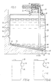
- Fig. 3 there is shown a section through line III-III in Fig. 2 of the calibrating solution vessel 35.
- the vessel has a cap 58 which is welded onto the top of the bottle at 59.
- the cap 58 has a cavity 60 having an outlet aperture 61 and inlet aperture 62.
- the vessel is supplied with a membrane sealing the outlet aperture 61.
- the inlet aperture 62 is formed in a tube 63 extending into the cavity 60. This tube is surrounded by an annular gasket 64 which extends beyond the tip of the tube 63.
- the bore of tube 63 extends through the back of the cavity 60 and into a second cavity 65 in which is held a tube 66 which extends down into the liquid 67 in the vessel, its end 68 being near to the bottom of the vessel.
- the vessel fits into a cavity 69 of the analyser 70, which has a substantially vertical wall 71 and a sloping base surface 72 which allows runoff of any liquid.
- the vessel 35 is shaped to correspond to the cavity 69, and thus has a sloping lower wall 73.
- the horizontally directed piercing member 74 has penetrated the membrane sealing the outlet aperture 61 to enter the cavity 60 and form a fluid tight seal with gasket 64.
- the position of the vessel with respect to the analyser 70 is determined in part by the communication of the member 74 with the vessel inlet aperture 62, and partly by the abutment of the walls of the vessel with the walls of the cavity 69 in the analyser.
- a protrusion 75 is molded in the back face 76 of the vessel, which serves to determine the position of the vessel with respect to the analyser. This protrusion has the additional function of maintaining a gap 77 between the wall 76 of the vessel and the vertical wall of the cavity, so that a capillary cannot be formed between the walls, to eliminate any electrically conducting reagent layers between the analyser and the vessel which might otherwise lead to electrical currents interfering with the electrical signals obtained with the measuring devices and thus to incorrect analysis results.
- the vessels shown in Fig. 2 are suspended from the rods extending into the cavity of the analyser by the provision of shoulders, as has been described above.
- the distance between the sides of the vessels shown in Fig. 2 aside from the shoulders formed at the tops of the sides, is substantially constant.
- the distance between the sides of adjacent vessels below the shoulders is sufficient for an operators fingers to be able to grab the sides of the bottle to withdraw it from the analyser.
- Alternative bottle profiles may be used which enable the vessels to be suspended from the same rods. Examples of alternative profiles are shown in Figs. 4a and b.
- the vessel shown in Fig. 4a has a shoulder 52 as well as a ridge 80 lower down the side.
- the ridge 80 ensures that the vessel is slid onto the analyser at exactly the right height and direction for registration of the cap of the vessel with the inlet mechanism of the analyser.
- FIG. 4b A further profile is shown in Fig. 4b, in which the shoulder is formed as the upper surface of a groove 81 formed in the side of the vessel.
- the shoulder is formed as the upper surface of a groove 81 formed in the side of the vessel.
- Fig. 5 shows a cross-section along line V-V in Fig. 2 of a rinse bottle prior to being received on an analyser.
- a cap 55 is mounted on the vessel 40 by welding at 59.
- the cap comprises a cavity 60 which has an outlet aperture 61 sealed by a foil 83 which is vapour impermeable.
- An inlet aperture 62 is formed in a tube 63 extending into the cavity and whose other end opens into a second cavity 65 into which is fitted a tube 66 which extends downwards into the base solution for forming the rinsing solution in the vessel.
- the cavity 60 includes an annular gasket 64 which forms a fluid tight fitting around the tube 63.
- a small hole 84 between the first cavity 60 and the second cavity 65 allows ingress of air into the second cavity 65 and thence into the vessel from the outside via aperture 61 and cavity 60 when the vessel is mounted on the analyser, as liquid is removed from the vessel.
- Fig. 5 there is also indicated the piercing member 74 of the inlet mechanism of the analyser, immediately prior to piercing of the foil seal 83.
- the cap 55 of the rinse solution vessel comprises a third cavity 85 in which is received a plunger 86 which has a pointed end 87.
- the end 87 penetrates the thin wall 88 of the third cavity 85 to form a fluid conduit from the third cavity into the inside of the vessel.
- a dried enzyme preparation is positioned within the cavity 85 adjacent the wall 88, so that it is dropped into the solution when the plunger 86 is depressed.
- the plunger has seals 89 and 90 to form a fluid tight seal within the cavity 85 to prevent liquid escaping from the vessel through cavity 85.
- the enzyme preparation is released into the base solution a few hours prior to use to ensure complete dissolution of the enzyme to form the desired rinse solution.
- Fig. 6 is a section along line VI-VI of Fig. 2 through the cap of a waste vessel.
- Vessel 26 comprises a cap 56 fixed to the vessel by welding at 91.
- the cap comprises a bottom plate 92 which has a central aperture 93 surrounded by a flange 94, as well as a top plate 95 having a snap fitting 96 depending from its centre which fits through the aperture 93 and is locked in position to allow relative rotational movement between the plates.
- the plate 95 has upwardly extending ridges 97 which can be gripped to rotate the top plate.
- Lower plate 92 has an aperture 98 which is surrounded on the upper surface of the plate by a circular ridge 99 molded into the plate.
- the upper plate has an aperture 100 which, when the cap is in the open position as indicated, is located immediately above the aperture 98.
- the circular ridge 99 contacts the lower face of the plate 95 to form a substantially fluid tight seal between the plates.
- the plates are held in the open position by the reception of a pin 101 on the upper plate in a socket 102 on the lower plate.
- the upper plate In the closed position, not shown in the diagram, the upper plate is rotated so that the aperture 100 is no longer positioned above the aperture 98, but so that a region of the upper plate occludes the aperture 98 and so that a fluid tight seal is formed by contact of the ridge 99 with the lower side of the plate 92.
- the plates may be secured in the closed position by the pin 101 being received in a different socket which is positioned at an appropriate point in the upper surface of the lower plate 92.
- the aligned apertures 98 and 100 are positioned vertically below the waste outlet 57 of the analyser so that any waste liquid discharged therefrom flows through the apertures and into the waste vessel.
- a calibrating solution having a pH of 7.400 ⁇ 0.005 at 37°C and which has a sodium ion concentration of 160.8 ⁇ 3 mmol/l and a chloride ion concentration of 106.2 ⁇ 1 mmol/l at 20°C is formed with the following ingredients: Sodium hydrogen carbonate 0.0226 g HEPES 23.7191 g Sodium hydroxide 2.1504 g Kathon 886 0.060 g Triton CF10 0.050 g Deionised water to 1,000 g
- a calibrating solution having a pH of 6.800 ⁇ 0.005 at 37°C and having a sodium ion concentration of 106.8 ⁇ 3 mmol/l and a chloride ion concentration of 118.4 ⁇ 1 mmol/l at 20°C contains the following ingredients: Kathon 886 0.060 g Triton CF10 0.050 g Sodium chloride 6.8505 g MOPS 20.8764 g Sodium hydroxide 1.6782 g Deionised water to 1,000 g
- a base solution is made up of the following components: Potassium chloride 3.728 g Sodium chloride 2.922 g Sodium hydrogen carbonate 0.0303 g Kathon 886 0.060 g Triton CF10 0.050 g Deionised water to 1,000 g
- the base solution contains sodium ions in a concentration of 50.5 ⁇ 1.0 mmol/l, potassium ions in an amount 50.2 ⁇ 1.0 mmol/l and chloride ions in an amount of 100.3 ⁇ 1.6 mmol/l at 20°C.
- the solution has a pH of 7.35 ⁇ 0.35.
- subtilisin enzyme is added to the base solution in an amount of 20 mg per 1000 g base solution.
- a salt bridge solution for the calomel electrode of the pH measuring part of the apparatus is formed from the following components: Potassium chloride 220 g Triton X100 0.43 g Kathon 886 0.06 g Deionised water to 1,000 g
- the solution contains potassium chloride in the amount of 2.951 ⁇ 0.040 mmol/kg of water.
- a cleaning solution for regular (e.g. daily) cleaning of the measuring part of the apparatus by being injected via the sample injection means comprises 200 g Deconex (trade mark) (tenside mixture) made up to 1,000 g with deionised water.
Landscapes
- Physics & Mathematics (AREA)
- Health & Medical Sciences (AREA)
- Life Sciences & Earth Sciences (AREA)
- Chemical & Material Sciences (AREA)
- Analytical Chemistry (AREA)
- Biochemistry (AREA)
- General Health & Medical Sciences (AREA)
- General Physics & Mathematics (AREA)
- Immunology (AREA)
- Pathology (AREA)
- Investigating Or Analysing Biological Materials (AREA)
- Sampling And Sample Adjustment (AREA)
- Automatic Analysis And Handling Materials Therefor (AREA)
- Analysing Materials By The Use Of Radiation (AREA)
- Measuring Or Testing Involving Enzymes Or Micro-Organisms (AREA)
Claims (4)
- Apparat umfassend ein Analysiergerät zur Durchführung von Messungen von Eigenschaften von Proben physiologischer Flüssigkeiten mit Übertragung von elektrischen Signalen durch das Analysiergerät, und ein auf dem Analysiergerät befestigbares Aufbewahrungsgefäß für Flüssig-reagens, in dem das Analysiergerät ein Flüssigkeitsleitungssystem mit einem Probeneinlassabschnitt, einem nach dem Einlassabschnitt angeordneten Messabschnitt, eine Flüssig-reagenzleitung und einen Flüssigreagens-Eingabemechanismus zur Leitung einer Strömung von Flüssigreagens aus dem Aufbewahrungsgefäß durch die Flüssigreagensleitung zum Messabschnitt umfasst, und das Analysiergerät ferner Tragemittel aufweist, die das Flüssigkeitsaufbewahrungsgefäß in seiner Position zum Zusammenwirken mit dem Flüssigreagens-Eingabemechanismus halten können, und worin das Aufbewahrungsgefäß eine im Wesentlichen vertikal weisende versiegelte Auslassöffnung aufweist, die im Oberteil des Gefäßes vorgesehen und seitlich relativ zum Eingabemechanismus angeordnet ist, dadurch gekennzeichnet, dass das Tragemittel zum Aufhängen des Gefäßes ein Paar parallel zueinander und im Wesentlichen auf derselben Höhe angeordneter Stangen aufweist die so am Analysiergerät befestigt sind, dass sie sich vom Analysiergerät nach außen erstrecken, dass das Gefäß an beiden Seiten zusammenwirkende Mittel zur Zusammenarbeit mit den Stangen aufweist, wobei die zusammenwirkenden Mittel eine Schulter im oberen Bereich jeder Gefäßseite aufweisen, die jeweils auf einer der Stangen ruht, wenn das Gefäß vom Analysiergerät gestützt wird, und dass der Eingabemechanismus des Apparats einen Schlauch mit offenen Ende aufweist, der so befestigt ist, dass er sich im Wesentlichen horizontal vom Analysiergerät erstreckt und das öffnungssiegel penetrieren kann, wenn das Aufbewahrungsgefäß auf dem Analysiergerät befestigt wird.
- Apparat nach Anspruch 1, dadurch gekennzeichnet, dass er eine Vielzahl von Gefäßen umfasst, wobei das Analysiergerät Tragemittel für jedes Gefäß aufweist, die so angeordnet sind, dass die Gefäße nebeneinander mit gegenüberliegenden Schultern auf der gleichen Höhe gestützt werden, damit eine einzelne Stange zwischen benachbarten Gefäßen beide Gefäße durch Zusammenwirken mit diesen Schultern stützen kann.
- Apparat nach Anspruch 1 oder 2, dadurch gekennzeichnet, dass die Gefäße von Seite bis Seite in einem Bereich der Vorderfläche enger sind und so einen Abstand zwischen den Gefäßen bilden, der ausreicht, damit ein Anwender die Seiten des Gefäßes zum Herausziehen aus dem Analysiergerät mit den Fingern greifen kann.
- Apparat nach Anspruch 3, dadurch gekennzeichnet, dass die Vorderfläche des gesamten Gefäßes schmäler ist als der Abstand zwischen der Ausdehnung der Schultern.
Applications Claiming Priority (3)
| Application Number | Priority Date | Filing Date | Title |
|---|---|---|---|
| GB8914456 | 1989-06-23 | ||
| GB898914456A GB8914456D0 (en) | 1989-06-23 | 1989-06-23 | Apparatus for analysis of samples of fluids |
| EP90910605A EP0478683B1 (de) | 1989-06-23 | 1990-06-13 | Gerät zur analyse von flüssigkeitsproben |
Related Parent Applications (2)
| Application Number | Title | Priority Date | Filing Date |
|---|---|---|---|
| EP90910605.6 Division | 1990-06-13 | ||
| EP90910605A Division EP0478683B1 (de) | 1989-06-23 | 1990-06-13 | Gerät zur analyse von flüssigkeitsproben |
Publications (2)
| Publication Number | Publication Date |
|---|---|
| EP0678746A1 EP0678746A1 (de) | 1995-10-25 |
| EP0678746B1 true EP0678746B1 (de) | 2001-11-21 |
Family
ID=10658949
Family Applications (2)
| Application Number | Title | Priority Date | Filing Date |
|---|---|---|---|
| EP95109518A Expired - Lifetime EP0678746B1 (de) | 1989-06-23 | 1990-06-13 | Gerät zur Analyse von Flüssigkeitsproben |
| EP90910605A Expired - Lifetime EP0478683B1 (de) | 1989-06-23 | 1990-06-13 | Gerät zur analyse von flüssigkeitsproben |
Family Applications After (1)
| Application Number | Title | Priority Date | Filing Date |
|---|---|---|---|
| EP90910605A Expired - Lifetime EP0478683B1 (de) | 1989-06-23 | 1990-06-13 | Gerät zur analyse von flüssigkeitsproben |
Country Status (8)
| Country | Link |
|---|---|
| US (2) | US5309775A (de) |
| EP (2) | EP0678746B1 (de) |
| JP (1) | JP2708275B2 (de) |
| AT (2) | ATE132270T1 (de) |
| DE (2) | DE69033868T2 (de) |
| DK (1) | DK0678746T3 (de) |
| GB (1) | GB8914456D0 (de) |
| WO (1) | WO1991000520A1 (de) |
Families Citing this family (20)
| Publication number | Priority date | Publication date | Assignee | Title |
|---|---|---|---|---|
| GB9208386D0 (en) * | 1992-04-16 | 1992-06-03 | Amersham Int Plc | Storage and dispensing device for liquids |
| US5641006A (en) * | 1995-07-13 | 1997-06-24 | Chiron Diagnostics Corporation | Liquid supply apparatus and method of operation |
| AT406913B (de) * | 1995-07-14 | 2000-10-25 | Avl Verbrennungskraft Messtech | In einen probenanalysator einsetzbare reagenzienflaschen |
| EP0847531A1 (de) * | 1995-08-30 | 1998-06-17 | Radiometer Medical A/S | Automatische zugabe von referenzflüssigkeiten in einem gerät zur analyse physiologischer flüssigkeiten |
| US6886421B2 (en) | 1997-07-21 | 2005-05-03 | Vijay Mathur | Modular film sensors with record memory for modular automated diagnostic apparatus |
| US5983734A (en) * | 1997-07-21 | 1999-11-16 | Medica Corporation | Modular automated diagnostic analysis apparatus with a self cleaning sample input port, an improved fluid selection port, and an improved reagent pack |
| US6193933B1 (en) * | 1997-10-27 | 2001-02-27 | Hitachi, Ltd. | Automatic analysis apparatus |
| DE10002475C1 (de) * | 2000-01-21 | 2001-05-31 | Roche Diagnostics Gmbh | Analysegerät zur Analyse von Proben |
| USD449687S1 (en) | 2000-08-31 | 2001-10-23 | Disetronic Licensing Ag | Needle shield for an injection device |
| USD443695S1 (en) | 2000-05-26 | 2001-06-12 | Avl Medical Instruments | Container for diagnostic analyzer |
| US6998270B2 (en) | 2001-11-26 | 2006-02-14 | Lab Vision Corporation | Automated tissue staining system and reagent container |
| US20040033163A1 (en) * | 2001-11-26 | 2004-02-19 | Lab Vision Corporation | Automated tissue staining system and reagent container |
| US20060003658A1 (en) * | 2004-06-30 | 2006-01-05 | Hall Gregory K | Elastic clothlike meltblown materials, articles containing same, and methods of making same |
| US8178177B2 (en) * | 2005-02-11 | 2012-05-15 | 3M Innovative Properties Company | Duct wrap and method for fire protecting a duct |
| US20060225795A1 (en) * | 2005-03-30 | 2006-10-12 | Baker George D | Push button regulator device with sealing element to facilitate easy connection with other devices |
| GB2432667A (en) * | 2005-09-06 | 2007-05-30 | Gwernafalau Gyfyngedig | Apparatus and method for the separation of material from biological samples |
| CN105759019B (zh) * | 2010-02-26 | 2019-05-31 | 希森美康株式会社 | 试剂容器以及试剂容器组件 |
| US10463222B2 (en) | 2013-11-27 | 2019-11-05 | Kimberly-Clark Worldwide, Inc. | Nonwoven tack cloth for wipe applications |
| CN105842013B (zh) * | 2016-04-28 | 2019-03-19 | 上海科勒电子科技有限公司 | 一种集液装置及包括该集液装置的智能马桶 |
| CN120629286A (zh) * | 2022-07-31 | 2025-09-12 | 深圳市理邦精密仪器股份有限公司 | 血气分析设备、检测组件、试剂盒 |
Family Cites Families (32)
| Publication number | Priority date | Publication date | Assignee | Title |
|---|---|---|---|---|
| CA660170A (en) * | 1963-03-26 | K. Hart Robert | Package | |
| US2644453A (en) * | 1951-08-11 | 1953-07-07 | Cutter Lab | Bottle stopper |
| US2859898A (en) * | 1956-10-03 | 1958-11-11 | Res Lab Inc | Container and a cap therefor, by means of which a user can prepare a fresh solution or suspension and can readily dispense the same |
| US3290920A (en) * | 1964-02-07 | 1966-12-13 | United States Steel Corp | Apparatus for calibrating vapor responsive detectors |
| GB1292151A (en) * | 1969-01-09 | 1972-10-11 | Radiometer As | Method and apparatus for determining at least one unknown data of a biological fluid |
| US3690833A (en) * | 1970-05-04 | 1972-09-12 | Damon Corp | Automated fluids analyzer having selectively interrupted flow |
| NL169380C (nl) * | 1975-05-09 | 1982-07-01 | Philips Nv | Tekenweergeefinrichting. |
| US4070156A (en) * | 1976-03-17 | 1978-01-24 | Hycel, Inc. | Reagent dispensing system in an automatic chemical analyzer |
| AT342343B (de) * | 1976-05-12 | 1978-03-28 | Koch Heinrich Dr | Resorptionsmodell |
| US4604263A (en) * | 1976-06-17 | 1986-08-05 | Analytical Products, Inc. | Cell for gas sample equilibrator |
| US4074976A (en) * | 1976-09-01 | 1978-02-21 | Gower Stephen G M | Leveling devices for use in high speed liquid sampling systems |
| DK151397C (da) * | 1979-02-23 | 1988-08-01 | Radiometer As | Fremgangsmaade og praeparat til brug ved drift af instrumenter, der analyserer proteinholdige biologiske vaesker |
| JPS5639455A (en) * | 1979-09-10 | 1981-04-15 | Olympus Optical Co Ltd | Method and device for measuring ion concentration |
| DE2951667A1 (de) * | 1979-12-21 | 1981-07-02 | Merck Patent Gmbh, 6100 Darmstadt | Transport- und entnahmevorrichtung |
| US4338280A (en) * | 1981-04-02 | 1982-07-06 | Instrumentation Laboratory Inc. | Fluid sampling |
| JPS595933A (ja) * | 1982-07-02 | 1984-01-12 | Hitachi Ltd | 液体試料のフロ−分析方法 |
| IT1158491B (it) * | 1982-12-24 | 1987-02-18 | Maria Manni | Vaschetta a fondo rastremato particolarmente per liquidi da pipettare mediante pipette multiple |
| US4711851A (en) * | 1984-05-21 | 1987-12-08 | State University Of New York | Test apparatus for determining a metabolic characteristic of microorganisms |
| GB2171982B (en) * | 1985-03-08 | 1989-01-11 | Metal Box Plc | Containers for use in detecting micro-organisms |
| JPS61249383A (ja) * | 1985-04-26 | 1986-11-06 | Kawasumi Lab Inc | 培養器具 |
| US4678752A (en) * | 1985-11-18 | 1987-07-07 | Becton, Dickinson And Company | Automatic random access analyzer |
| JPH079416B2 (ja) * | 1986-01-31 | 1995-02-01 | 株式会社日立製作所 | 液体試料の流れ分析方法 |
| DE3616062A1 (de) * | 1986-05-13 | 1987-11-19 | Fresenius Ag | Verfahren zur bestimmung von gaspartialdruecken im blut sowie vorrichtung zur durchfuehrung des verfahrens |
| EP0252632B1 (de) * | 1986-07-11 | 1994-08-31 | Beckman Instruments, Inc. | Reagenzkassette |
| DK159837C (da) * | 1986-12-03 | 1991-04-29 | Radiometer As | Fremgangsmaade og apparat til afsloering af en proteinforurening paa en ph elektrode |
| US5284621A (en) * | 1987-10-07 | 1994-02-08 | Kaufman Jack W | Waste fluid disposal aid |
| US5185263A (en) * | 1987-10-23 | 1993-02-09 | Avl Medical Instruments Ag | Method for calibration of a measurement apparatus |
| FR2637254A1 (fr) * | 1988-10-03 | 1990-04-06 | Schiemann Dr Wolfram | Dispositif pour bidon en matiere plastique |
| US4928860A (en) * | 1989-01-23 | 1990-05-29 | Knight Jeffrey J | Dispensing container |
| USD325257S (en) | 1989-06-23 | 1992-04-07 | Radiometer A/S | Container for waste expelled from a blood gas analyzer or the like |
| USD325259S (en) | 1989-06-23 | 1992-04-07 | Radiometer A/S | Container for waste expelled from a blood gas analyzer or the like |
| USD325258S (en) | 1989-06-23 | 1992-04-07 | Radiometer A/S | Container for waste expelled from a blood gas analyzer or the like |
-
1989
- 1989-06-23 GB GB898914456A patent/GB8914456D0/en active Pending
-
1990
- 1990-06-13 WO PCT/DK1990/000147 patent/WO1991000520A1/en not_active Ceased
- 1990-06-13 DE DE69033868T patent/DE69033868T2/de not_active Expired - Lifetime
- 1990-06-13 DK DK95109518T patent/DK0678746T3/da active
- 1990-06-13 AT AT90910605T patent/ATE132270T1/de not_active IP Right Cessation
- 1990-06-13 JP JP2509931A patent/JP2708275B2/ja not_active Expired - Lifetime
- 1990-06-13 EP EP95109518A patent/EP0678746B1/de not_active Expired - Lifetime
- 1990-06-13 US US07/778,850 patent/US5309775A/en not_active Expired - Lifetime
- 1990-06-13 AT AT95109518T patent/ATE209361T1/de not_active IP Right Cessation
- 1990-06-13 DE DE69024494T patent/DE69024494D1/de not_active Expired - Lifetime
- 1990-06-13 EP EP90910605A patent/EP0478683B1/de not_active Expired - Lifetime
-
1994
- 1994-01-13 US US08/180,605 patent/US5417121A/en not_active Expired - Lifetime
Also Published As
| Publication number | Publication date |
|---|---|
| EP0478683A1 (de) | 1992-04-08 |
| US5417121A (en) | 1995-05-23 |
| JP2708275B2 (ja) | 1998-02-04 |
| DK0678746T3 (da) | 2002-05-21 |
| US5309775A (en) | 1994-05-10 |
| DE69033868T2 (de) | 2002-06-27 |
| DE69033868D1 (de) | 2002-01-03 |
| GB8914456D0 (en) | 1989-08-09 |
| EP0478683B1 (de) | 1995-12-27 |
| DE69024494D1 (de) | 1996-02-08 |
| ATE209361T1 (de) | 2001-12-15 |
| ATE132270T1 (de) | 1996-01-15 |
| EP0678746A1 (de) | 1995-10-25 |
| WO1991000520A1 (en) | 1991-01-10 |
Similar Documents
| Publication | Publication Date | Title |
|---|---|---|
| EP0678746B1 (de) | Gerät zur Analyse von Flüssigkeitsproben | |
| JPH04503571A (ja) | 液体試料の分析装置 | |
| US5208147A (en) | Means for measuring a characteristic in a sample fluid | |
| US4729876A (en) | Blood analysis system | |
| US5114859A (en) | Method for measuring a characteristic in a sample fluid | |
| US5863754A (en) | Process for bacteria identification and for determination of the sensitivity of bacteria to antibiotics and apparatus and measuring supports for carrying out this process | |
| US5555920A (en) | Method and apparatus for aliquotting blood serum or blood plasma | |
| US4785677A (en) | Pipetting device having an automatic mechanism for replacing nozzle tips | |
| US4649028A (en) | Electrolyte analyzer | |
| US5542575A (en) | Liquid reagent container having a primary and secondary closure mechanism | |
| EP1921439B1 (de) | Messvorrichtung, messgerät und messverfahren | |
| US4705668A (en) | Electrolyte analyzer | |
| US5322192A (en) | Pipetting apparatus | |
| US20080044908A1 (en) | Method of Normalizing Surface Tension of a Sample Fluid | |
| CN220064066U (zh) | 一种生化分析仪 | |
| CN115248331A (zh) | Poct血细胞分析仪及其使用方法、移液器 | |
| CN215180255U (zh) | Poct血细胞分析仪 | |
| CN216525869U (zh) | Poct血细胞分析仪、检测座 | |
| CN219540345U (zh) | 样本采集容器、离心组件及样本分析仪 | |
| CN221506371U (zh) | 一种尿液分析仪的取尿试管结构 | |
| CN216525867U (zh) | Poct血细胞分析仪 | |
| CN215866723U (zh) | Poct血细胞分析仪 | |
| CN216387080U (zh) | Poct血细胞分析仪、试剂盒 | |
| CN216525868U (zh) | Poct血细胞分析仪 | |
| JPH0316060Y2 (de) |
Legal Events
| Date | Code | Title | Description |
|---|---|---|---|
| PUAI | Public reference made under article 153(3) epc to a published international application that has entered the european phase |
Free format text: ORIGINAL CODE: 0009012 |
|
| 17P | Request for examination filed |
Effective date: 19950620 |
|
| AC | Divisional application: reference to earlier application |
Ref document number: 478683 Country of ref document: EP |
|
| AK | Designated contracting states |
Kind code of ref document: A1 Designated state(s): AT CH DE DK FR GB IT LI NL |
|
| GRAG | Despatch of communication of intention to grant |
Free format text: ORIGINAL CODE: EPIDOS AGRA |
|
| 17Q | First examination report despatched |
Effective date: 19971201 |
|
| GRAG | Despatch of communication of intention to grant |
Free format text: ORIGINAL CODE: EPIDOS AGRA |
|
| GRAG | Despatch of communication of intention to grant |
Free format text: ORIGINAL CODE: EPIDOS AGRA |
|
| GRAG | Despatch of communication of intention to grant |
Free format text: ORIGINAL CODE: EPIDOS AGRA |
|
| GRAH | Despatch of communication of intention to grant a patent |
Free format text: ORIGINAL CODE: EPIDOS IGRA |
|
| GRAH | Despatch of communication of intention to grant a patent |
Free format text: ORIGINAL CODE: EPIDOS IGRA |
|
| GRAA | (expected) grant |
Free format text: ORIGINAL CODE: 0009210 |
|
| AC | Divisional application: reference to earlier application |
Ref document number: 478683 Country of ref document: EP |
|
| AK | Designated contracting states |
Kind code of ref document: B1 Designated state(s): AT CH DE DK FR GB IT LI NL |
|
| PG25 | Lapsed in a contracting state [announced via postgrant information from national office to epo] |
Ref country code: NL Free format text: LAPSE BECAUSE OF FAILURE TO SUBMIT A TRANSLATION OF THE DESCRIPTION OR TO PAY THE FEE WITHIN THE PRESCRIBED TIME-LIMIT Effective date: 20011121 Ref country code: LI Free format text: LAPSE BECAUSE OF FAILURE TO SUBMIT A TRANSLATION OF THE DESCRIPTION OR TO PAY THE FEE WITHIN THE PRESCRIBED TIME-LIMIT Effective date: 20011121 Ref country code: IT Free format text: LAPSE BECAUSE OF FAILURE TO SUBMIT A TRANSLATION OF THE DESCRIPTION OR TO PAY THE FEE WITHIN THE PRE;WARNING: LAPSES OF ITALIAN PATENTS WITH EFFECTIVE DATE BEFORE 2007 MAY HAVE OCCURRED AT ANY TIME BEFORE 2007. THE CORRECT EFFECTIVE DATE MAY BE DIFFERENT FROM THE ONE RECORDED.SCRIBED TIME-LIMIT Effective date: 20011121 Ref country code: CH Free format text: LAPSE BECAUSE OF FAILURE TO SUBMIT A TRANSLATION OF THE DESCRIPTION OR TO PAY THE FEE WITHIN THE PRESCRIBED TIME-LIMIT Effective date: 20011121 |
|
| REF | Corresponds to: |
Ref document number: 209361 Country of ref document: AT Date of ref document: 20011215 Kind code of ref document: T |
|
| REG | Reference to a national code |
Ref country code: CH Ref legal event code: EP |
|
| REG | Reference to a national code |
Ref country code: GB Ref legal event code: IF02 |
|
| REF | Corresponds to: |
Ref document number: 69033868 Country of ref document: DE Date of ref document: 20020103 |
|
| NLV1 | Nl: lapsed or annulled due to failure to fulfill the requirements of art. 29p and 29m of the patents act | ||
| REG | Reference to a national code |
Ref country code: DK Ref legal event code: T3 |
|
| REG | Reference to a national code |
Ref country code: CH Ref legal event code: PL |
|
| PLBE | No opposition filed within time limit |
Free format text: ORIGINAL CODE: 0009261 |
|
| STAA | Information on the status of an ep patent application or granted ep patent |
Free format text: STATUS: NO OPPOSITION FILED WITHIN TIME LIMIT |
|
| 26N | No opposition filed | ||
| PGFP | Annual fee paid to national office [announced via postgrant information from national office to epo] |
Ref country code: DK Payment date: 20090629 Year of fee payment: 20 |
|
| PGFP | Annual fee paid to national office [announced via postgrant information from national office to epo] |
Ref country code: FR Payment date: 20090617 Year of fee payment: 20 Ref country code: AT Payment date: 20090520 Year of fee payment: 20 |
|
| PGFP | Annual fee paid to national office [announced via postgrant information from national office to epo] |
Ref country code: GB Payment date: 20090625 Year of fee payment: 20 Ref country code: DE Payment date: 20090629 Year of fee payment: 20 |
|
| REG | Reference to a national code |
Ref country code: DK Ref legal event code: EUP |
|
| REG | Reference to a national code |
Ref country code: GB Ref legal event code: PE20 Expiry date: 20100612 |
|
| PG25 | Lapsed in a contracting state [announced via postgrant information from national office to epo] |
Ref country code: GB Free format text: LAPSE BECAUSE OF EXPIRATION OF PROTECTION Effective date: 20100612 |
|
| PG25 | Lapsed in a contracting state [announced via postgrant information from national office to epo] |
Ref country code: DE Free format text: LAPSE BECAUSE OF EXPIRATION OF PROTECTION Effective date: 20100613 |