EP0678748A1 - Procédé de mesure de la vitesse d'un courant de particules - Google Patents
Procédé de mesure de la vitesse d'un courant de particules Download PDFInfo
- Publication number
- EP0678748A1 EP0678748A1 EP95104344A EP95104344A EP0678748A1 EP 0678748 A1 EP0678748 A1 EP 0678748A1 EP 95104344 A EP95104344 A EP 95104344A EP 95104344 A EP95104344 A EP 95104344A EP 0678748 A1 EP0678748 A1 EP 0678748A1
- Authority
- EP
- European Patent Office
- Prior art keywords
- speed
- measuring
- particles
- distribution
- signals
- Prior art date
- Legal status (The legal status is an assumption and is not a legal conclusion. Google has not performed a legal analysis and makes no representation as to the accuracy of the status listed.)
- Granted
Links
- 239000002245 particle Substances 0.000 title claims abstract description 34
- 238000000034 method Methods 0.000 title claims abstract description 23
- 238000009826 distribution Methods 0.000 claims abstract description 35
- 108010076504 Protein Sorting Signals Proteins 0.000 claims description 8
- 210000004072 lung Anatomy 0.000 claims 1
- 238000005259 measurement Methods 0.000 abstract description 15
- 239000000463 material Substances 0.000 abstract description 2
- 238000004381 surface treatment Methods 0.000 abstract 1
- 238000005422 blasting Methods 0.000 description 26
- 230000004888 barrier function Effects 0.000 description 8
- 238000005480 shot peening Methods 0.000 description 8
- 229910000831 Steel Inorganic materials 0.000 description 5
- 239000003795 chemical substances by application Substances 0.000 description 5
- 239000010959 steel Substances 0.000 description 5
- 230000003287 optical effect Effects 0.000 description 4
- 230000001133 acceleration Effects 0.000 description 3
- 238000000691 measurement method Methods 0.000 description 3
- 239000003082 abrasive agent Substances 0.000 description 2
- 230000001419 dependent effect Effects 0.000 description 2
- 238000004088 simulation Methods 0.000 description 2
- 238000006467 substitution reaction Methods 0.000 description 2
- 230000003247 decreasing effect Effects 0.000 description 1
- 230000005294 ferromagnetic effect Effects 0.000 description 1
- 230000010354 integration Effects 0.000 description 1
- 230000008092 positive effect Effects 0.000 description 1
- 230000003068 static effect Effects 0.000 description 1
- 238000005728 strengthening Methods 0.000 description 1
- 239000002344 surface layer Substances 0.000 description 1
Images


Classifications
-
- G—PHYSICS
- G01—MEASURING; TESTING
- G01P—MEASURING LINEAR OR ANGULAR SPEED, ACCELERATION, DECELERATION, OR SHOCK; INDICATING PRESENCE, ABSENCE, OR DIRECTION, OF MOVEMENT
- G01P3/00—Measuring linear or angular speed; Measuring differences of linear or angular speeds
- G01P3/64—Devices characterised by the determination of the time taken to traverse a fixed distance
- G01P3/68—Devices characterised by the determination of the time taken to traverse a fixed distance using optical means, i.e. using infrared, visible, or ultraviolet light
Definitions
- the invention relates to a method for measuring the speed of a particle stream, the individual particles of which move independently of one another in a substantially the same direction. At least a partial stream of the particles is exposed to light rays that trigger a light signal sequence.
- a small measurement volume is illuminated with a light beam. If a beam particle crosses this volume, the light is reflected on two slits of different widths, which are at a defined distance from each other.
- the signal sequence received by an optical detector assigned to the slots only has a certain light-to-dark-to-light ratio if the light signal sequence originates from a single beam particle. In this case, the duration of the light signal sequence received by the optical detector is inversely proportional to the speed of the beam particle.
- the shot peening method has proven itself for the strengthening and forming of components.
- jet particles are shot onto the component accelerated, whereby a thin surface layer facing the shot peening is plasticized and stretched. This induces residual stresses in the component cross-section, which have a positive effect on the material properties.
- the abrasive intensity is chosen so high that a macroscopic one- or two-dimensional curvature of the component is also created.
- the speed of the blasting media has a significant influence on the result of the forming in all mechanical blasting processes. It is therefore of great interest to have an easy-to-use speed measurement method.
- the invention has for its object to propose such a measuring method that can be used with all abrasives and allows a simple analysis of the signals required to determine the speed.
- the blasting medium speed is thus determined by measuring the time it takes for a blasting particle to travel through a defined distance ds.
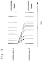
- two light beams are directed at particles of the abrasive stream at a defined distance and either the transmitting or the reflecting signals are recorded as a function of time with an optical detector. If there are small blasting media flows, there are usually only individual blasting particles in the measuring setup. If these particles pass through the first light beam, a characteristic signal is registered by the optical detector, which signal is shifted by a time interval dt and is also detected by the second measuring point, as shown in FIG. 1.
- each of the signals detected on the second light beam could have been generated by the particle which gave the start signal for the measurement, as illustrated in FIG. 3.
- a speed is first of all determined according to every time interval dt i assigned.
- this method results in a cluster point at the correct blasting medium speed v.
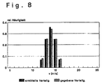
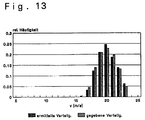
- the background speed distribution is subtracted from the determined total distribution (sum of real speed distribution + background speed distribution), whereupon the resulting difference distribution gives the real speed distribution of the blasting medium.
- the measurement method described above is then applied to the simulated signal sequence and the "real" speed distribution is determined. If the measuring method according to the invention works reliably, it must reproduce the simulated blast medium velocity distribution.
- the predetermined distributions are compared with the determined distributions. Regardless of the specified average speed and the type of blasting medium speed distribution selected, there is good agreement between the individual distributions.
- the blasting medium velocity distributions determined by the speed measurement method generally have a smaller width or standard deviation than the predetermined distributions.
- the maximum relative deviation from the specified standard deviation ⁇ v is in any case less than 5%.
- the expected speed values determined with the measuring method agree with the predetermined mean speeds, for which reference is made to FIG. 14.
- the method according to the invention was tested on a 7-axis CNC-controlled shot peening system.
- steel balls with a diameter of 4 mm to 10 mm can be accelerated.
- Blasting agent dosing of the 8 mm balls from 5 to 30 kg / min deliver 100 to 1,000 signals in a measuring interval of approx. 1 sec.
- the number of accelerated steel balls increases rapidly with the same dosage, which means that even for the smallest measuring intervals ( ⁇ T ⁇ 1 s), a sufficiently large number of signals can be detected and a reliable speed measurement can thus be carried out, as illustrated in FIG. 15.
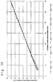
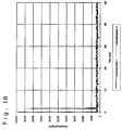
- the blasting medium Although a straight line movement of the blasting medium, which is directed parallel to the connecting line of the light barriers, was assumed to determine the blasting medium speed, the blasting medium generally has a speed component oriented perpendicular to the beam direction. Dependent on this is the distance ds' actually covered by the balls between the light barriers and thus the experimentally determined speed v 2 according to FIG. 16.
- v2 denotes the experimentally determined and v1 the actual speed of the steel ball.
- the speed measurement can be done with with greater accuracy:
- the error that occurs can be minimized by the targeted selection of the light beam diameter depending on the blasting agent used.
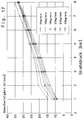
- FIG. 17 shows the dependence of the blasting medium speed on the set blasting pressure and blasting medium flow. It can clearly be seen that the spherical velocity v K is strongly dependent on the selected spherical jet parameters, namely acceleration pressure and mass flow.
Landscapes
- Physics & Mathematics (AREA)
- General Physics & Mathematics (AREA)
- Investigating Or Analysing Materials By Optical Means (AREA)
- Length Measuring Devices By Optical Means (AREA)
- Indicating Or Recording The Presence, Absence, Or Direction Of Movement (AREA)
Applications Claiming Priority (2)
| Application Number | Priority Date | Filing Date | Title |
|---|---|---|---|
| DE4412494A DE4412494C2 (de) | 1994-04-12 | 1994-04-12 | Verfahren zur Messung der Geschwindigkeitsverteilung eines Strahlmittelstromes |
| DE4412494 | 1994-04-12 |
Publications (2)
| Publication Number | Publication Date |
|---|---|
| EP0678748A1 true EP0678748A1 (fr) | 1995-10-25 |
| EP0678748B1 EP0678748B1 (fr) | 2000-05-10 |
Family
ID=6515154
Family Applications (1)
| Application Number | Title | Priority Date | Filing Date |
|---|---|---|---|
| EP95104344A Expired - Lifetime EP0678748B1 (fr) | 1994-04-12 | 1995-03-24 | Procédé de mesure de la vitesse d'un courant de particules |
Country Status (3)
| Country | Link |
|---|---|
| US (1) | US5691483A (fr) |
| EP (1) | EP0678748B1 (fr) |
| DE (2) | DE4412494C2 (fr) |
Cited By (1)
| Publication number | Priority date | Publication date | Assignee | Title |
|---|---|---|---|---|
| DE102007013221B3 (de) * | 2007-03-15 | 2008-08-14 | Ksa Kugelstrahlzentrum Aachen Gmbh | Verfahren zur Bestimmung des Abstandes zwischen zwei Erfassungsstellen einer Geschwindigkeitsmesseinrichtung für Partikel |
Families Citing this family (9)
| Publication number | Priority date | Publication date | Assignee | Title |
|---|---|---|---|---|
| US6624434B1 (en) * | 1999-04-21 | 2003-09-23 | Sarnoff Corporation | Apparatus for measurement of particle or droplet velocity |
| US6192813B1 (en) | 1999-05-21 | 2001-02-27 | Flexi-Coil Ltd. | Apparatus for controlling the flow rate of an air seeder |
| US6158363A (en) * | 1999-05-21 | 2000-12-12 | Flexi-Coil Ltd. | Apparatus for dispensing particles |
| CN100442055C (zh) * | 2005-06-10 | 2008-12-10 | 中国科学院空间科学与应用研究中心 | 一种微粒速度的激光散射测量系统 |
| DE102006021223A1 (de) * | 2006-05-06 | 2007-11-08 | Mtu Aero Engines Gmbh | Verfahren zum Oberflächenstrahlen eines Bauteils |
| WO2016165029A1 (fr) * | 2015-04-17 | 2016-10-20 | Protecsom Amerique Du Nord Inc. | Appareil de mesure optique du débit et appareil d'inhalation le comprenant |
| DE102015223155A1 (de) | 2015-11-24 | 2017-05-24 | Robert Bosch Gmbh | Messung der Strahlkraft in einer Feststoffstrahlanlage |
| FI20165678A7 (fi) * | 2016-09-12 | 2018-03-13 | Oseir Oy | Menetelmä ja laitteisto kuulapuhalluksen ohjaamiseksi |
| US20240269801A1 (en) * | 2023-02-09 | 2024-08-15 | Electronics Inc. | Controlling shot peening device via shot media velocity sensing |
Citations (4)
| Publication number | Priority date | Publication date | Assignee | Title |
|---|---|---|---|---|
| DE3106530A1 (de) * | 1981-02-21 | 1982-09-09 | Baier, Paul Walter, Prof. Dr. | Einrichtung zur ermittlung momentaner stroemungsgeschwindigkeiten |
| EP0100304A1 (fr) * | 1982-06-11 | 1984-02-08 | Gedevelop Aktiebolag | Procédé et appareil pour déterminer la vitesse d'écoulement d'une matière fondue émettante de rayonnement |
| EP0302431A2 (fr) * | 1987-07-31 | 1989-02-08 | The Titan Corporation | Système et procédé pour la détermination du mouvement d'un aéronef dans l'atmosphère |
| US4873855A (en) * | 1988-05-02 | 1989-10-17 | General Electric Company | Shot sensing shot peening system and method |
Family Cites Families (4)
| Publication number | Priority date | Publication date | Assignee | Title |
|---|---|---|---|---|
| LU61023A1 (fr) * | 1970-05-29 | 1971-08-12 | ||
| US5064603A (en) * | 1989-08-24 | 1991-11-12 | Westinghouse Electric Corp. | Hydroball string sensing system |
| US5176018A (en) * | 1991-10-02 | 1993-01-05 | General Electric Company | Shot sensing shot peening system and method having a capacitance based densitometer |
| US5186057A (en) * | 1991-10-21 | 1993-02-16 | Everhart Howard R | Multi-beam liquid-drop size/rate detector apparatus |
-
1994
- 1994-04-12 DE DE4412494A patent/DE4412494C2/de not_active Expired - Fee Related
-
1995
- 1995-03-24 EP EP95104344A patent/EP0678748B1/fr not_active Expired - Lifetime
- 1995-03-24 DE DE59508296T patent/DE59508296D1/de not_active Expired - Lifetime
- 1995-04-11 US US08/420,062 patent/US5691483A/en not_active Expired - Lifetime
Patent Citations (4)
| Publication number | Priority date | Publication date | Assignee | Title |
|---|---|---|---|---|
| DE3106530A1 (de) * | 1981-02-21 | 1982-09-09 | Baier, Paul Walter, Prof. Dr. | Einrichtung zur ermittlung momentaner stroemungsgeschwindigkeiten |
| EP0100304A1 (fr) * | 1982-06-11 | 1984-02-08 | Gedevelop Aktiebolag | Procédé et appareil pour déterminer la vitesse d'écoulement d'une matière fondue émettante de rayonnement |
| EP0302431A2 (fr) * | 1987-07-31 | 1989-02-08 | The Titan Corporation | Système et procédé pour la détermination du mouvement d'un aéronef dans l'atmosphère |
| US4873855A (en) * | 1988-05-02 | 1989-10-17 | General Electric Company | Shot sensing shot peening system and method |
Cited By (3)
| Publication number | Priority date | Publication date | Assignee | Title |
|---|---|---|---|---|
| DE102007013221B3 (de) * | 2007-03-15 | 2008-08-14 | Ksa Kugelstrahlzentrum Aachen Gmbh | Verfahren zur Bestimmung des Abstandes zwischen zwei Erfassungsstellen einer Geschwindigkeitsmesseinrichtung für Partikel |
| EP1970712A2 (fr) | 2007-03-15 | 2008-09-17 | KSA Kugelstrahlzentrum Aachen GmbH | Procédé destiné à la détermination de l'écart entre deux positions de saisie d'un dispositif de mesure de vitesse pour particules |
| EP1970712A3 (fr) * | 2007-03-15 | 2011-11-23 | KSA Kugelstrahlzentrum Aachen GmbH | Procédé destiné à la détermination de l'écart entre deux positions de saisie d'un dispositif de mesure de vitesse pour particules |
Also Published As
| Publication number | Publication date |
|---|---|
| DE4412494C2 (de) | 1997-02-27 |
| US5691483A (en) | 1997-11-25 |
| DE59508296D1 (de) | 2000-06-15 |
| DE4412494A1 (de) | 1995-10-19 |
| EP0678748B1 (fr) | 2000-05-10 |
Similar Documents
| Publication | Publication Date | Title |
|---|---|---|
| EP0678748B1 (fr) | Procédé de mesure de la vitesse d'un courant de particules | |
| DE69202927T2 (de) | Kugelstrahlverfahren für Werkstücke mit einer Methode zum Messen der Intensität und Anlage zur Durchführung des Verfahrens. | |
| EP0059745A1 (fr) | Procede et dispositif de localisation et d'analyse d'emissions sonores. | |
| EP0991532A1 (fr) | Procede permettant de determiner un nombre de tours d'une roue de vehicule tournant autour d'un axe de rotation | |
| DE102012102363A1 (de) | Verfahren und Vorrichtung zur Bestimmung der Größe eines transparenten Teilchens | |
| EP1153398A1 (fr) | Systeme de balayage a faisceau ionique et procede permettant de faire fonctionner ce systeme | |
| DE102016116523B4 (de) | Vibrationsanalysevorrichtung, die einen Zyklus der Werkzeugvibration in Bezug zum Werkstück berechnet | |
| EP0150396B1 (fr) | Procédé et dispositif pour la mesure optique d'écoulement d'un fluide | |
| DE4227787C2 (de) | Verfahren zum Bestimmen der Einlaufgeschwindigkeit von Eisenbahnfahrzeugen in eine Meßstrecke | |
| DE3033990A1 (de) | Verfahren und vorrichtung zur schallemissions-ortung und -analyse | |
| WO2022135978A1 (fr) | Dispositif de détermination de données pour la détermination de la vitesse d'un véhicule, dispositif d'analyse et procédé associé | |
| WO2021191104A1 (fr) | Procédé et dispositif de mesure pour déterminer la vitesse de particules d'un aérosol | |
| WO2016180907A1 (fr) | Dispositif et procédé pour le comptage et/ou la mesure de particules dans un flux de liquide | |
| DE19716264C2 (de) | Vorrichtung und Verfahren zur Überprüfung einer Oberfläche eines Gegenstands | |
| DE102014211514B4 (de) | Verfahren zur Bestimmung des Durchsatzes, des Volumenstromes und des Massenstromes von Teilchen | |
| EP0638797B1 (fr) | Dispositif laser à effet doppler et procédé de mise en oeuvre | |
| CH440734A (de) | Einrichtung zum Bestimmen von Abmessungen an Körpern | |
| DE102018125205B4 (de) | Verfahren und Vorrichtung zur Ermittlung des Verschleißgrades einer Spritzdüse | |
| DE10034281A1 (de) | Dosimetrieverfahren und Dosimetrie-Vorrichtung für aus einer Gasphase auf Zellschichten abgelagerte Aerosolpartikel | |
| DE2233741A1 (de) | Verfahren zur raeumlichen trennung von komponenten eines molekularstrahls | |
| DE19736711C1 (de) | Meßverfahren zum Bestimmen der Achsengeschwindigkeit einer Wagenachse | |
| DE10332713B3 (de) | Strahlintensitätsmessvorrichtung für Oberflächenbehandlungseinrichtungen | |
| EP0420109A1 (fr) | Procédé et dispositif de mesure de débit massique dans un canal ou plusieurs phases sont en écoulement | |
| DE2003753A1 (de) | Blendenanordnung zur Begrenzung eines Roentgenstrahlenbuendels | |
| DE10138489B4 (de) | Verfahren und Vorrichtung zur Bestimmung der Richtung und der Geschwindigkeit eines Förderstromes |
Legal Events
| Date | Code | Title | Description |
|---|---|---|---|
| PUAI | Public reference made under article 153(3) epc to a published international application that has entered the european phase |
Free format text: ORIGINAL CODE: 0009012 |
|
| AK | Designated contracting states |
Kind code of ref document: A1 Designated state(s): CH DE FR GB LI NL |
|
| 17P | Request for examination filed |
Effective date: 19960326 |
|
| 17Q | First examination report despatched |
Effective date: 19971212 |
|
| GRAG | Despatch of communication of intention to grant |
Free format text: ORIGINAL CODE: EPIDOS AGRA |
|
| GRAG | Despatch of communication of intention to grant |
Free format text: ORIGINAL CODE: EPIDOS AGRA |
|
| GRAH | Despatch of communication of intention to grant a patent |
Free format text: ORIGINAL CODE: EPIDOS IGRA |
|
| GRAH | Despatch of communication of intention to grant a patent |
Free format text: ORIGINAL CODE: EPIDOS IGRA |
|
| GRAA | (expected) grant |
Free format text: ORIGINAL CODE: 0009210 |
|
| AK | Designated contracting states |
Kind code of ref document: B1 Designated state(s): CH DE FR GB LI NL |
|
| REG | Reference to a national code |
Ref country code: CH Ref legal event code: EP |
|
| REF | Corresponds to: |
Ref document number: 59508296 Country of ref document: DE Date of ref document: 20000615 |
|
| GBT | Gb: translation of ep patent filed (gb section 77(6)(a)/1977) |
Effective date: 20000706 |
|
| ET | Fr: translation filed | ||
| PLBE | No opposition filed within time limit |
Free format text: ORIGINAL CODE: 0009261 |
|
| STAA | Information on the status of an ep patent application or granted ep patent |
Free format text: STATUS: NO OPPOSITION FILED WITHIN TIME LIMIT |
|
| 26N | No opposition filed | ||
| REG | Reference to a national code |
Ref country code: GB Ref legal event code: IF02 |
|
| PGFP | Annual fee paid to national office [announced via postgrant information from national office to epo] |
Ref country code: NL Payment date: 20060305 Year of fee payment: 12 |
|
| PGFP | Annual fee paid to national office [announced via postgrant information from national office to epo] |
Ref country code: CH Payment date: 20060329 Year of fee payment: 12 |
|
| REG | Reference to a national code |
Ref country code: CH Ref legal event code: PL |
|
| NLV4 | Nl: lapsed or anulled due to non-payment of the annual fee |
Effective date: 20071001 |
|
| PG25 | Lapsed in a contracting state [announced via postgrant information from national office to epo] |
Ref country code: NL Free format text: LAPSE BECAUSE OF NON-PAYMENT OF DUE FEES Effective date: 20071001 |
|
| PG25 | Lapsed in a contracting state [announced via postgrant information from national office to epo] |
Ref country code: LI Free format text: LAPSE BECAUSE OF NON-PAYMENT OF DUE FEES Effective date: 20070331 Ref country code: CH Free format text: LAPSE BECAUSE OF NON-PAYMENT OF DUE FEES Effective date: 20070331 |
|
| PGFP | Annual fee paid to national office [announced via postgrant information from national office to epo] |
Ref country code: DE Payment date: 20140331 Year of fee payment: 20 |
|
| PGFP | Annual fee paid to national office [announced via postgrant information from national office to epo] |
Ref country code: GB Payment date: 20140331 Year of fee payment: 20 |
|
| PGFP | Annual fee paid to national office [announced via postgrant information from national office to epo] |
Ref country code: FR Payment date: 20140328 Year of fee payment: 20 |
|
| REG | Reference to a national code |
Ref country code: DE Ref legal event code: R071 Ref document number: 59508296 Country of ref document: DE |
|
| REG | Reference to a national code |
Ref country code: GB Ref legal event code: PE20 Expiry date: 20150323 |
|
| PG25 | Lapsed in a contracting state [announced via postgrant information from national office to epo] |
Ref country code: GB Free format text: LAPSE BECAUSE OF EXPIRATION OF PROTECTION Effective date: 20150323 |