EP1970712A2 - Procédé destiné à la détermination de l'écart entre deux positions de saisie d'un dispositif de mesure de vitesse pour particules - Google Patents
Procédé destiné à la détermination de l'écart entre deux positions de saisie d'un dispositif de mesure de vitesse pour particules Download PDFInfo
- Publication number
- EP1970712A2 EP1970712A2 EP08002799A EP08002799A EP1970712A2 EP 1970712 A2 EP1970712 A2 EP 1970712A2 EP 08002799 A EP08002799 A EP 08002799A EP 08002799 A EP08002799 A EP 08002799A EP 1970712 A2 EP1970712 A2 EP 1970712A2
- Authority
- EP
- European Patent Office
- Prior art keywords
- points
- detection
- distance
- detection points
- specimen
- Prior art date
- Legal status (The legal status is an assumption and is not a legal conclusion. Google has not performed a legal analysis and makes no representation as to the accuracy of the status listed.)
- Granted
Links
Images



Classifications
-
- G—PHYSICS
- G01—MEASURING; TESTING
- G01P—MEASURING LINEAR OR ANGULAR SPEED, ACCELERATION, DECELERATION, OR SHOCK; INDICATING PRESENCE, ABSENCE, OR DIRECTION, OF MOVEMENT
- G01P5/00—Measuring speed of fluids, e.g. of air stream; Measuring speed of bodies relative to fluids, e.g. of ship, of aircraft
- G01P5/18—Measuring speed of fluids, e.g. of air stream; Measuring speed of bodies relative to fluids, e.g. of ship, of aircraft by measuring the time taken to traverse a fixed distance
- G01P5/20—Measuring speed of fluids, e.g. of air stream; Measuring speed of bodies relative to fluids, e.g. of ship, of aircraft by measuring the time taken to traverse a fixed distance using particles entrained by a fluid stream
-
- G—PHYSICS
- G01—MEASURING; TESTING
- G01P—MEASURING LINEAR OR ANGULAR SPEED, ACCELERATION, DECELERATION, OR SHOCK; INDICATING PRESENCE, ABSENCE, OR DIRECTION, OF MOVEMENT
- G01P21/00—Testing or calibrating of apparatus or devices covered by the preceding groups
- G01P21/02—Testing or calibrating of apparatus or devices covered by the preceding groups of speedometers
- G01P21/025—Testing or calibrating of apparatus or devices covered by the preceding groups of speedometers for measuring speed of fluids; for measuring speed of bodies relative to fluids
-
- G—PHYSICS
- G01—MEASURING; TESTING
- G01S—RADIO DIRECTION-FINDING; RADIO NAVIGATION; DETERMINING DISTANCE OR VELOCITY BY USE OF RADIO WAVES; LOCATING OR PRESENCE-DETECTING BY USE OF THE REFLECTION OR RERADIATION OF RADIO WAVES; ANALOGOUS ARRANGEMENTS USING OTHER WAVES
- G01S17/00—Systems using the reflection or reradiation of electromagnetic waves other than radio waves, e.g. lidar systems
- G01S17/02—Systems using the reflection of electromagnetic waves other than radio waves
- G01S17/50—Systems of measurement based on relative movement of target
- G01S17/58—Velocity or trajectory determination systems; Sense-of-movement determination systems
-
- G—PHYSICS
- G01—MEASURING; TESTING
- G01S—RADIO DIRECTION-FINDING; RADIO NAVIGATION; DETERMINING DISTANCE OR VELOCITY BY USE OF RADIO WAVES; LOCATING OR PRESENCE-DETECTING BY USE OF THE REFLECTION OR RERADIATION OF RADIO WAVES; ANALOGOUS ARRANGEMENTS USING OTHER WAVES
- G01S17/00—Systems using the reflection or reradiation of electromagnetic waves other than radio waves, e.g. lidar systems
- G01S17/87—Combinations of systems using electromagnetic waves other than radio waves
Definitions
- the invention relates to a method for determining the effective measuring distance between two detection points of a device for measuring the velocity of a stream of free-flying particles, wherein at each detection point of a passing particle, a signal can be generated and the speed of the current through a statistical evaluation of a variety of the particles generated signals can be calculated, with a specimen with known geometry is guided past the detection points and from the signals generated thereby, the distance between the detection points is determined.
- a device for measuring the velocity of a flow of free-flying particles is known from EP 0 678 748 A1 known. Such a device and the underlying measuring method are used in particular in the so-called shot peening, which serves to reshape workpieces by the particle bombardment either in the most accurate predeterminable geometry or solidify by the construction of targeted compressive stresses.
- the speed of the blasting medium is determined by measuring the times required for a plurality of particles to pass through a particular measuring distance.
- two photocells with known distance are used as detection points, which are directed to the blasting agent and interrupted by the passing particles.
- the signals are registered with optical detectors as a function of time.
- the light barrier distance may possibly be greater than the particle diameter.
- the particle velocity can be determined by statistical interpretation of the pulse sequence.
- initially a particle or a pulse is considered at the first light barrier. Starting from this pulse, the time differences are determined for all later pulses at the second light barrier and from this the associated speeds. At this point, however, it is not possible to decide which speed of the determined speed values is the true particle velocity.
- the true particle velocity is determined K times, while the other, non-applicable velocities, which are referred to as the background signal, are distributed over the entire velocity range.
- the so-called sum distribution of the speed determined as explained above has a falling course with increasing speed and has a local maximum. If one subtracts the background signal from this sum distribution, the result is the true velocity distribution of the particles whose maximum represents the mean measured velocity.
- the two light barriers are scanned for a certain time with a very high quartz-stabilized frequency, for example 20 MHz.
- a very high quartz-stabilized frequency for example 20 MHz.
- a light barrier distance of about 0.5 mm and a realistic speed of the particles during shot peening of, for example, 100 m / s
- a passing time for one particle is achieved by the two light barriers of 5 ⁇ s.
- an inherent error of ⁇ 1% results in the detection of a single particle.
- the mean error is significantly lower because of the large number of particles detected. Since the number of detected particles is very high, the error is negligible due to the discrete-time reading of the pulses in practice.
- a major source of error for potentially inaccurate speed values is an erroneously detected or time varying, effective photoelectric distance.
- the photoelectric distance effective in one measurement may be affected by external influences, e.g. Pollution, change and must therefore be calibrated regularly during use of the measuring device.
- the geometric distance which can be determined geometrically, for example with the aid of a linear scale or a measuring microscope, is not identical to the effective measuring distance effective during measurement operation:
- both detectors must be darkened to a certain extent in order to detect a particle passing through the light barriers. If, for example, the proportion of the darkened area, the switching threshold, in both detectors is 50% of the total detector area, then the effective light barrier distance is identical to the geometric one. If, however, differences in the amplifier electronics of one of the two detectors, e.g. already at 40% darkening produces a pulse, then effective and geometric light barrier distance are no longer identical. Depending on which of the two detectors has a smaller switching threshold, the effective distance between the photoelectric barriers is either greater or smaller than the geometric photoelectric distance. The influence of differing switching thresholds is greater the larger the detectors are in relation to their distance.
- Another influencing factor on the effective measuring distance is uneven permanent contamination or damage to the two detectors. For example, if one half of a detector is dirty, then there is a change in the effective photoelectric distance between the two detectors at 50% switching threshold, since the 50% darkening of the remaining area will occur sooner or later than adequate coverage of the non-effective area. It is assumed that the contamination itself as a steady state does not lead to the triggering of a pulse signal, but is compensated by an automatic readjustment of the signal conditioning.
- the alignment of the light sources and the detectors has an influence on the effective measuring distance. If, for example, the two light beams which illuminate the detectors are not exactly parallel but run obliquely to one another, an effective measuring distance deviating from the geometrical light barrier spacing results.
- the effective measuring distance and the geometric light barrier distance are generally not identical, so that the effective measuring distance must be determined with a suitable calibration method.
- the effective measuring distance can be determined as the mean value of the previously obtained values.
- the aforementioned procedure for carrying out drop tests has the disadvantage that the calibration process is tedious and the sensor with the two light barriers has to be removed from the shot peening system in order to be able to carry out the drop tests. The cost of regularly performed calibration is therefore considerable in the known approach.
- the US 2003/0142289 A1 discloses, in particular in the local figure 13 with the corresponding description text, a method for calibrating a device for measuring the velocity of a particle flow.
- the particles are bead-like arranged on a carriage and moved at a defined speed through the flow channel in the flow direction, while data recorded and evaluated by means of an optical measuring apparatus.
- US 4,373,816 A a device and a method for determining surface distances, wherein a test piece is moved in rotation with release points and when scanning the surface time differences are measured as optical path lengths.
- the invention has for its object to provide a method for calibrating a measuring device for determining the velocity of a particle stream, ie a method for determining the effective measuring distance between two detection points, the proposed method should be easy to perform and at the same time provide a sufficiently high accuracy.
- this object is achieved in that the specimen has a plurality of spaced apart and successively arranged release points whose spatial arrangement is known to each other, and that when passing each trigger point at each detection point, a signal is generated from the temporal signal sequences generated at the two detection points of the plurality of release points, the distance of the detection points to each other is determined.
- the calibration of the measuring device can be attributed very simply to the exact length measurement of the specimen, ie the measurement of the distance between the detection points. It is not necessary that the release points all have the same distance from each other, but it is only necessary to know the distance of the release points from each other. If the speed of the specimen can not be considered approximately constant when passing at the detection points - However, what is almost always possible with appropriate design of the specimen - as well as an accelerated movement of the specimen during the phase of passing the detection points is possible, in which case, however, for the determination of the effective measuring distance, the course of acceleration over time during the passage must be known.
- the particles of the particle stream and the release points of the specimen are detected at the detection points in an optical manner, preferably by means of light barriers.
- a light barrier arrangement should be located at each detection point, the light barrier, which defined a detection cross-section, is interrupted by passing particles of the current as well as by the release points of the specimen, which have a change in light transmittance.
- These may be reflection light barriers or transmission light barriers.
- the particles and the release points of the specimen are detected at the detection points in an inductive or capacitive manner.
- a coil arrangement is then located at each detection point, particles of the current passing through the detection cross-section and the triggering points of the test body inducing a signal.
- capacitive detection signal generation is caused in accordance with a change in the electric field strength at the detection points.
- the specimen may have a sequence of alternating light-transmitting and opaque portions each having known, preferably within the group of translucent sections and within the group of opaque portions each of identical length.
- the specimen is thus, for example, a lattice structure, e.g. in the form of a sheet metal strip consisting of alternately successively arranged translucent sections (clearances or cut-out areas) and opaque sections.
- the translucent sections may be formed as a linear succession arranged apertures preferably rectangular in shape.
- a glass strip which is opaque in sections as a test specimen.
- the same test specimen should be passed successively past the detection points and, after each pass, a value of the effective measuring distance of the detection points to each other determined and then an average of the above values of individual passages as a result the effective measuring distance of the detection points are determined.
- a value for the effective measuring distance of the detection points should only be determined and output at a passing of the sample at the detection points, if a minimum number of valid signals of the temporal signal sequences at both the first Measuring point as well as at the second detection point.
- the output of a result for the effective measuring distance should only take place if the number of signals of the temporal signal sequence of the first detection point coincides with the number of signals of the temporal signal sequence of the second detection point.
- the time between the generation of the signal assigned to the first trigger point of the test specimen and the signal assigned to the last trigger point of the specimen should not exceed or exceed a certain maximum time for control purposes do not fall short of a certain minimum time.
- the sample is passed manually by an operator at the detection points.
- the specimen should be guided past the detection points along a guide device, preferably along a linear guide rail.
- the guide means may be temporarily mounted on the speed measuring device or else permanently attached thereto, as long as the measuring operation in beam operation is not hindered or impaired by the guide device.
- the specimen can also be guided past the detection points by means of a drive device, which is preferably supplied with external energy.
- the detection points of two light barriers are formed to. to measure the velocity of the two light beams passing one behind the other.
- s LS can, for known light barrier distance s, ie at a known effective distance of the detection points S Detection point, eff , the speed of a passing particle can be determined.
- known methods can be determined by a statistical interpretation of the pulses, the velocity of the particles, if their number is sufficiently large and the particles move independently.
- the geometric distance s LS, Geo of the two light barriers, ie the geometric distance S Detection point, Geo the detection points from each other, can be measured in a relatively simple manner, for example by means of a linear scale, (eg measuring microscope, ruler, etc.).
- a linear scale eg measuring microscope, ruler, etc.
- the geometric light barrier distance is generally not identical with the effective photoelectric distance when measuring the particle velocity:
- the light barriers forming the detection points consist, on the one hand, of a light source emitting a light beam and a detector having a photosensitive field to which the respective light beam is directed.
- the light beam is interrupted by the flow of the particles to be detected and therefore the impact of the light beam on the photosensitive field of the detector is temporarily prevented.
- FIG. 1a shows a schematic representation of two light-sensitive detectors 1.1 and 1.2 whose center lines 2.1 and 2.2 are in a geometric photoelectric distance s l, S, Geo to each other.
- An edge length of the square shape possessing photosensitive field of the detectors 1.1 and 1.2 has the dimension s detector .
- the detectors 1.1. and 1.2 are darkened to their particular part of the area of the photosensitive field. If the proportion of the surface to be darkened, the switching threshold, for both detectors 1.1. and 1.2 is, for example, 50%, the effective light barrier distance s LS, eff is identical to the geometric light barrier distance s LS, Geo , as in Fig. 1b ) is shown.
- an identity of the two switching thresholds is not always present; rather, the switching thresholds deviate from one another, for example as a result of differences in the amplifier electronics. If, for example, one of the two detectors 1.1 already generates a pulse at 40% darkening, then effective and geometric light barrier distance are no longer identical. Owns as in Fig. 1c ), the first swept detector 1.1 in the direction of flight 3 of the particles is a lower switching threshold, the effective light barrier distance S LS, eff is greater than the geometric light barrier distance S LS, Geo . Conversely, the conditions in the in Figure 1d ) illustrated case in which the second swept in the direction of flight 3 detector 1.2 has the smaller switching threshold.
- FIGS. 2a) to 2c) is the influence of uneven permanent contamination or damage of the two detectors 1.1. and 1.2 illustrates.
- the two detectors 1.1 and 1.2 have the two center lines 2.1 and 2.2. the two detectors 1.1 and 1.2 a distance S LS, Geo from each other.
- the constellation according to FIG. 2b match the effective and geometric photoelectric distance, since the photosensitive fields of both detectors 1.1 and 1.2, as in the ideal case, are completely unpolluted.
- the upper half of the detector 1.1 for example, permanently soiled or so damaged that no light passage is possible in this area. In this case results at a switching threshold of 50% of the actually existing or, remaining.
- Residual area of the photosensitive field at both detectors a lower effective photoelectric distance s LS, eff . as this corresponds to the geometrical light barrier distance s LS, Geo . It should be assumed that no impulse signal is triggered by the contamination or damage itself, but that as a result of an automatic electronic readjustment of the signal processing, a compensation of the lost photosensitive surface portion takes place.
- FIG. 3a shows two light sources 4.1 and 4.2 emanating from two light sources 5.1 and 5.2, which are aligned with the center lines 2.1 and 2.2 of the two detectors 1.1 and 1.2.
- the two light beams 4.1 and 4.2 are aligned exactly parallel to one another, so that the effective light barrier distance S LS, eff , which is decisive for the particles flying along the line 6 , corresponds to the geometric light barrier distance S LS, Geo .
- the light beams 4.1 and 4.2 do not run parallel to each other due to a non-exact alignment of the light sources 5.1 and 5.2, but diverge. Since the line 6, on which the particles move, is located at a distance 7 from the detectors 1.1 and 1.2, the effective distance between the light barriers is less than the geometrical one, since the distance of the light rays determining the triggering of the pulses is due to their divergence in the region of the line 6 is less than the distance between the center lines 2.1 and 2.2 at the detectors, ie the geometric light barrier distance.
- the number n should be greater than 3.
- the cutouts 9 are all the same size and shape and are also aligned parallel to each other and arranged linearly at an identical distance from each other.
- the width of a web 11 and the width of a section 9 result in the sum of the distance s i, grid, in the case of the present lattice structure with identical cutouts 9 and webs 11th always consistent.
- the release points 15 of the grid structure are formed by the light-dark transitions at the longitudinal edges of the webs 11.
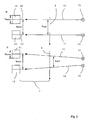
- FIG. 4 In the right half of the FIG. 4 is once approximately to scale and on the other hand diagonally right above the clarity of the enlarged scale, consisting of the two light barriers 10.1 and 10.2 existing sensor arrangement for detecting the moving along the line 12 particles.
- the sample 8 which is a light / dark structure of known geometry, preferably along a linear guide rail 13 through the light barriers 10.1 and 10.2 moves, then the light-impermeable webs 11 and the translucent cutouts 9 at a time distance to one another characteristic signal sequence at the two light barriers 10.1 and 10.2.
- the illustrated by the arrow 14 direction of movement of the grid corresponds to the direction of movement of the particles that fly through the light barrier arrangement in beam operation of the device. While the particle beam system is not in operation during the calibration process, the sensor arrangement does not have to be dismantled during the passage.
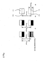
- FIG. 5 shows in the upper half of the diagram at the first in the direction of movement interrupted light barrier 10.1 resulting pulse sequence, whereas the lower half of the diagram illustrates the pulse sequence at the "later" photocell 10.2.
- a minimum time and a maximum time for the passage of the entire length of the specimen 8 is prescribed by the sensor arrangement.
- a minimum time and a maximum time for the passage of the entire length of the specimen 8 is prescribed by the sensor arrangement.
- time ⁇ 2 may t i, 1 and ⁇ t i do not deviate more than a certain amount from each other. This means that preferably at both detection points parallel to each other, the time intervals between the signals of two release points, ie adjacent webs or sections, ie light-dark transitions, detected and compared.
- the standard deviation of the determined values for ⁇ t i should not exceed a certain level in order to ensure the uniformity of the movement of the lattice structure through the sensor arrangement.
- the geometric light barrier distance s LS, G e o 0.5 mm the distance between two light-dark transitions, ie release points of the specimen (8) 6.0 mm.
- a minimum time for the implementation of the entire specimen 8 through the measuring arrangement can be assumed for example by a value of 0.3 s and for the maximum time of 2.0 s.
- a minimum of 10 pulses should be measured at both the first and second photocells.
- the deviation of the time ⁇ t i, 1 and ⁇ t i, 2 should be a maximum of ⁇ 2.5%. refer, for example, to the larger of the two times.
- the standard deviation of ⁇ t 1 should not be greater than ⁇ 2.5%, based on the determined ⁇ t i .
Landscapes
- Physics & Mathematics (AREA)
- Engineering & Computer Science (AREA)
- Electromagnetism (AREA)
- General Physics & Mathematics (AREA)
- Computer Networks & Wireless Communication (AREA)
- Radar, Positioning & Navigation (AREA)
- Remote Sensing (AREA)
- Aviation & Aerospace Engineering (AREA)
- Length Measuring Devices By Optical Means (AREA)
- Measuring Volume Flow (AREA)
Applications Claiming Priority (1)
| Application Number | Priority Date | Filing Date | Title |
|---|---|---|---|
| DE102007013221A DE102007013221B3 (de) | 2007-03-15 | 2007-03-15 | Verfahren zur Bestimmung des Abstandes zwischen zwei Erfassungsstellen einer Geschwindigkeitsmesseinrichtung für Partikel |
Publications (4)
| Publication Number | Publication Date |
|---|---|
| EP1970712A2 true EP1970712A2 (fr) | 2008-09-17 |
| EP1970712A8 EP1970712A8 (fr) | 2009-01-21 |
| EP1970712A3 EP1970712A3 (fr) | 2011-11-23 |
| EP1970712B1 EP1970712B1 (fr) | 2012-11-28 |
Family
ID=39539498
Family Applications (1)
| Application Number | Title | Priority Date | Filing Date |
|---|---|---|---|
| EP08002799A Active EP1970712B1 (fr) | 2007-03-15 | 2008-02-15 | Procédé destiné à la détermination de l'écart entre deux positions de saisie d'un dispositif de mesure de vitesse pour particules |
Country Status (2)
| Country | Link |
|---|---|
| EP (1) | EP1970712B1 (fr) |
| DE (1) | DE102007013221B3 (fr) |
Citations (4)
| Publication number | Priority date | Publication date | Assignee | Title |
|---|---|---|---|---|
| US4373816A (en) | 1981-01-09 | 1983-02-15 | Morvue, Inc. | Scanning beam optical position determining apparatus and method |
| EP0678748A1 (fr) | 1994-04-12 | 1995-10-25 | Kugelstrahlzentrum Aachen GmbH | Procédé de mesure de la vitesse d'un courant de particules |
| US20030142289A1 (en) | 2000-08-25 | 2003-07-31 | Amnis Corporation | Methods of calibrating an imaging system using calibration beads |
| EP1460433A2 (fr) | 2003-03-21 | 2004-09-22 | LaVision GmbH | Méthode de détermination de l'équation de conjugaison pour l'autocalibration des procédés Stéréo-PIV |
Family Cites Families (1)
| Publication number | Priority date | Publication date | Assignee | Title |
|---|---|---|---|---|
| US5517298A (en) * | 1993-06-01 | 1996-05-14 | Virginia Tech Intellectual Properties, Inc | Diode array velocimeter |
-
2007
- 2007-03-15 DE DE102007013221A patent/DE102007013221B3/de not_active Expired - Fee Related
-
2008
- 2008-02-15 EP EP08002799A patent/EP1970712B1/fr active Active
Patent Citations (4)
| Publication number | Priority date | Publication date | Assignee | Title |
|---|---|---|---|---|
| US4373816A (en) | 1981-01-09 | 1983-02-15 | Morvue, Inc. | Scanning beam optical position determining apparatus and method |
| EP0678748A1 (fr) | 1994-04-12 | 1995-10-25 | Kugelstrahlzentrum Aachen GmbH | Procédé de mesure de la vitesse d'un courant de particules |
| US20030142289A1 (en) | 2000-08-25 | 2003-07-31 | Amnis Corporation | Methods of calibrating an imaging system using calibration beads |
| EP1460433A2 (fr) | 2003-03-21 | 2004-09-22 | LaVision GmbH | Méthode de détermination de l'équation de conjugaison pour l'autocalibration des procédés Stéréo-PIV |
Also Published As
| Publication number | Publication date |
|---|---|
| EP1970712B1 (fr) | 2012-11-28 |
| DE102007013221B3 (de) | 2008-08-14 |
| EP1970712A3 (fr) | 2011-11-23 |
| EP1970712A8 (fr) | 2009-01-21 |
Similar Documents
| Publication | Publication Date | Title |
|---|---|---|
| EP2210078B1 (fr) | Procédé pour déterminer la pression et la profondeur de sculpture d'un pneumatique de véhicule | |
| EP2089670B1 (fr) | Procédé et dispositif de mesure d'épaisseur | |
| EP0039900B1 (fr) | Procédé et dispositif de mesure de la vitesse angulaire d'un corps en rotation | |
| EP2106530B1 (fr) | Procédé et dispositif pour détecter la surface tridimensionnelle d'un objet, en particulier d'un pneu de véhicule | |
| DE19708014A1 (de) | Vorrichtung und Verfahren zum Erfassen eines Objekts in einem vorgegebenen Raumbereich, insbesondere von Fahrzeugen für die Verkehrsüberwachung | |
| EP3386675B1 (fr) | Procédé pour déterminer la position focale de référence d'un faisceau laser | |
| DE102012102608B4 (de) | Verfahren zur Ermittlung von Strahlparametern eines Ladungsträgerstrahls, Messeinrichtung sowie Ladungsträgerstrahlvorrichtung | |
| DE2054285A1 (de) | Vorrichtung zur Prazisionsmessung von Abmessungen von Prüflingen | |
| EP1024372A1 (fr) | Dispositif pour détecter la position | |
| EP4127655B1 (fr) | Procédé et dispositif de mesure pour déterminer la vitesse de particules d'un aérosol | |
| WO2022135978A1 (fr) | Dispositif de détermination de données pour la détermination de la vitesse d'un véhicule, dispositif d'analyse et procédé associé | |
| AT516759B1 (de) | Vorrichtung und Verfahren zur Ermittlung der Anzahl an Feststoffpartikeln in einem Fluidstrom | |
| DE3913159A1 (de) | Verfahren und vorrichtung zur messung von wellenfoermigen deformationen an wenigstens einer schienenoberseite (schienenlaufflaeche) eines schienenweges | |
| DE3030229A1 (de) | Verfahren zur erkennung und identifikation von sich bewegenden objekten sowie zur ermittlung ihrer geschwindigkeit | |
| DE2750109C2 (de) | Vorrichtung zur kontaktlosen Messung linearer Wegstrecken, insbesondere des Durchmessers | |
| EP1970712B1 (fr) | Procédé destiné à la détermination de l'écart entre deux positions de saisie d'un dispositif de mesure de vitesse pour particules | |
| DE102004031024A1 (de) | Optischer Sensor | |
| EP2116814B1 (fr) | Dispositif de mesure destiné à la détermination d'une position et/ou d'une vitesse | |
| DE102012002127B3 (de) | Verfahren und Vorrichtung zur Erkennung von Oberflächenrissen | |
| EP0726445A2 (fr) | Procédé et dispositif pour mesurer le volume d'un objet en mouvement | |
| DE3522809C2 (fr) | ||
| EP3385721B1 (fr) | Barrière lumineuse | |
| DE102011109511A1 (de) | Verfahren zur Steuerung einer Produktionsanlage mittels einer hochauflösenden Ortsverfolgung von Werkstücken | |
| EP0083082A2 (fr) | Procédé et dispositif pour mesurer la longueur d'une droite ou d'une courbe | |
| WO2005052568A1 (fr) | Procede de determination quantitative de la longueur d'une region de zone molle d'une piece partiellement durcie |
Legal Events
| Date | Code | Title | Description |
|---|---|---|---|
| PUAI | Public reference made under article 153(3) epc to a published international application that has entered the european phase |
Free format text: ORIGINAL CODE: 0009012 |
|
| AK | Designated contracting states |
Kind code of ref document: A2 Designated state(s): AT BE BG CH CY CZ DE DK EE ES FI FR GB GR HR HU IE IS IT LI LT LU LV MC MT NL NO PL PT RO SE SI SK TR |
|
| AX | Request for extension of the european patent |
Extension state: AL BA MK RS |
|
| PUAL | Search report despatched |
Free format text: ORIGINAL CODE: 0009013 |
|
| AK | Designated contracting states |
Kind code of ref document: A3 Designated state(s): AT BE BG CH CY CZ DE DK EE ES FI FR GB GR HR HU IE IS IT LI LT LU LV MC MT NL NO PL PT RO SE SI SK TR |
|
| AX | Request for extension of the european patent |
Extension state: AL BA MK RS |
|
| RIC1 | Information provided on ipc code assigned before grant |
Ipc: G01P 5/20 20060101AFI20111015BHEP Ipc: G01S 17/87 20060101ALI20111015BHEP Ipc: G01P 21/02 20060101ALI20111015BHEP Ipc: G01S 17/58 20060101ALI20111015BHEP |
|
| 17P | Request for examination filed |
Effective date: 20120130 |
|
| REG | Reference to a national code |
Ref country code: DE Ref legal event code: R079 Ref document number: 502008008731 Country of ref document: DE Free format text: PREVIOUS MAIN CLASS: G01P0001020000 Ipc: G01P0005200000 |
|
| GRAP | Despatch of communication of intention to grant a patent |
Free format text: ORIGINAL CODE: EPIDOSNIGR1 |
|
| AKX | Designation fees paid |
Designated state(s): DE FR GB |
|
| RIC1 | Information provided on ipc code assigned before grant |
Ipc: G01S 17/58 20060101ALI20120626BHEP Ipc: G01S 17/87 20060101ALI20120626BHEP Ipc: G01P 5/20 20060101AFI20120626BHEP Ipc: G01P 21/02 20060101ALI20120626BHEP |
|
| GRAS | Grant fee paid |
Free format text: ORIGINAL CODE: EPIDOSNIGR3 |
|
| GRAA | (expected) grant |
Free format text: ORIGINAL CODE: 0009210 |
|
| AK | Designated contracting states |
Kind code of ref document: B1 Designated state(s): DE FR GB |
|
| REG | Reference to a national code |
Ref country code: GB Ref legal event code: FG4D Free format text: NOT ENGLISH |
|
| REG | Reference to a national code |
Ref country code: DE Ref legal event code: R096 Ref document number: 502008008731 Country of ref document: DE Effective date: 20130124 |
|
| PLBE | No opposition filed within time limit |
Free format text: ORIGINAL CODE: 0009261 |
|
| STAA | Information on the status of an ep patent application or granted ep patent |
Free format text: STATUS: NO OPPOSITION FILED WITHIN TIME LIMIT |
|
| 26N | No opposition filed |
Effective date: 20130829 |
|
| REG | Reference to a national code |
Ref country code: DE Ref legal event code: R097 Ref document number: 502008008731 Country of ref document: DE Effective date: 20130829 |
|
| REG | Reference to a national code |
Ref country code: FR Ref legal event code: PLFP Year of fee payment: 9 |
|
| REG | Reference to a national code |
Ref country code: FR Ref legal event code: PLFP Year of fee payment: 10 |
|
| REG | Reference to a national code |
Ref country code: FR Ref legal event code: PLFP Year of fee payment: 11 |
|
| REG | Reference to a national code |
Ref country code: DE Ref legal event code: R082 Ref document number: 502008008731 Country of ref document: DE Representative=s name: BAUER WAGNER PELLENGAHR SROKA PATENT- & RECHTS, DE Ref country code: DE Ref legal event code: R082 Ref document number: 502008008731 Country of ref document: DE Representative=s name: BAUER PSU PARTG MBB, DE |
|
| P01 | Opt-out of the competence of the unified patent court (upc) registered |
Effective date: 20230525 |
|
| PGFP | Annual fee paid to national office [announced via postgrant information from national office to epo] |
Ref country code: GB Payment date: 20260223 Year of fee payment: 19 |
|
| PGFP | Annual fee paid to national office [announced via postgrant information from national office to epo] |
Ref country code: DE Payment date: 20260228 Year of fee payment: 19 |
|
| PGFP | Annual fee paid to national office [announced via postgrant information from national office to epo] |
Ref country code: FR Payment date: 20260227 Year of fee payment: 19 |