EP0678757A1 - Verfahren zur Messung der Entfernung einer Strahlung - Google Patents
Verfahren zur Messung der Entfernung einer Strahlung Download PDFInfo
- Publication number
- EP0678757A1 EP0678757A1 EP95400848A EP95400848A EP0678757A1 EP 0678757 A1 EP0678757 A1 EP 0678757A1 EP 95400848 A EP95400848 A EP 95400848A EP 95400848 A EP95400848 A EP 95400848A EP 0678757 A1 EP0678757 A1 EP 0678757A1
- Authority
- EP
- European Patent Office
- Prior art keywords
- optical
- crystal
- detector crystal
- doped
- optical fiber
- Prior art date
- Legal status (The legal status is an assumption and is not a legal conclusion. Google has not performed a legal analysis and makes no representation as to the accuracy of the status listed.)
- Withdrawn
Links
- 230000005855 radiation Effects 0.000 title claims abstract description 44
- 238000000034 method Methods 0.000 title description 3
- 239000013078 crystal Substances 0.000 claims abstract description 88
- 239000013307 optical fiber Substances 0.000 claims abstract description 71
- 230000003287 optical effect Effects 0.000 claims abstract description 50
- VYPSYNLAJGMNEJ-UHFFFAOYSA-N Silicium dioxide Chemical compound O=[Si]=O VYPSYNLAJGMNEJ-UHFFFAOYSA-N 0.000 claims abstract description 38
- 239000000463 material Substances 0.000 claims abstract description 31
- FVAUCKIRQBBSSJ-UHFFFAOYSA-M sodium iodide Chemical compound [Na+].[I-] FVAUCKIRQBBSSJ-UHFFFAOYSA-M 0.000 claims abstract description 24
- 239000000377 silicon dioxide Substances 0.000 claims abstract description 19
- 238000001514 detection method Methods 0.000 claims abstract description 18
- 239000011521 glass Substances 0.000 claims abstract description 17
- 229910010272 inorganic material Inorganic materials 0.000 claims abstract description 16
- 239000011147 inorganic material Substances 0.000 claims abstract description 16
- XJHCXCQVJFPJIK-UHFFFAOYSA-M caesium fluoride Chemical compound [F-].[Cs+] XJHCXCQVJFPJIK-UHFFFAOYSA-M 0.000 claims abstract description 8
- HSZCZNFXUDYRKD-UHFFFAOYSA-M lithium iodide Chemical compound [Li+].[I-] HSZCZNFXUDYRKD-UHFFFAOYSA-M 0.000 claims abstract description 8
- 235000009518 sodium iodide Nutrition 0.000 claims abstract description 8
- OYPRJOBELJOOCE-UHFFFAOYSA-N Calcium Chemical compound [Ca] OYPRJOBELJOOCE-UHFFFAOYSA-N 0.000 claims abstract description 4
- 229910052797 bismuth Inorganic materials 0.000 claims abstract description 4
- JCXGWMGPZLAOME-UHFFFAOYSA-N bismuth atom Chemical compound [Bi] JCXGWMGPZLAOME-UHFFFAOYSA-N 0.000 claims abstract description 4
- 229910052793 cadmium Inorganic materials 0.000 claims abstract description 4
- BDOSMKKIYDKNTQ-UHFFFAOYSA-N cadmium atom Chemical compound [Cd] BDOSMKKIYDKNTQ-UHFFFAOYSA-N 0.000 claims abstract description 4
- 229910052791 calcium Inorganic materials 0.000 claims abstract description 4
- 239000011575 calcium Substances 0.000 claims abstract description 4
- WUKWITHWXAAZEY-UHFFFAOYSA-L calcium difluoride Chemical compound [F-].[F-].[Ca+2] WUKWITHWXAAZEY-UHFFFAOYSA-L 0.000 claims abstract description 4
- 239000005387 chalcogenide glass Substances 0.000 claims abstract description 4
- YBMRDBCBODYGJE-UHFFFAOYSA-N germanium oxide Inorganic materials O=[Ge]=O YBMRDBCBODYGJE-UHFFFAOYSA-N 0.000 claims abstract description 4
- 239000005304 optical glass Substances 0.000 claims abstract description 4
- PVADDRMAFCOOPC-UHFFFAOYSA-N oxogermanium Chemical compound [Ge]=O PVADDRMAFCOOPC-UHFFFAOYSA-N 0.000 claims abstract description 4
- 150000004763 sulfides Chemical class 0.000 claims abstract description 4
- 229910001634 calcium fluoride Inorganic materials 0.000 claims abstract description 3
- 230000003993 interaction Effects 0.000 claims description 14
- 238000004020 luminiscence type Methods 0.000 claims description 13
- 230000001902 propagating effect Effects 0.000 claims description 2
- 238000005253 cladding Methods 0.000 abstract description 7
- 239000002019 doping agent Substances 0.000 abstract description 2
- 229910052761 rare earth metal Inorganic materials 0.000 abstract description 2
- 150000002910 rare earth metals Chemical class 0.000 abstract description 2
- 239000005383 fluoride glass Substances 0.000 abstract 2
- PBYZMCDFOULPGH-UHFFFAOYSA-N tungstate Chemical compound [O-][W]([O-])(=O)=O PBYZMCDFOULPGH-UHFFFAOYSA-N 0.000 abstract 2
- 239000000835 fiber Substances 0.000 description 34
- 230000035945 sensitivity Effects 0.000 description 10
- 238000005259 measurement Methods 0.000 description 9
- 238000004980 dosimetry Methods 0.000 description 8
- 230000007423 decrease Effects 0.000 description 6
- 239000004033 plastic Substances 0.000 description 5
- 229920003023 plastic Polymers 0.000 description 5
- PEDCQBHIVMGVHV-UHFFFAOYSA-N Glycerine Chemical compound OCC(O)CO PEDCQBHIVMGVHV-UHFFFAOYSA-N 0.000 description 4
- 238000004519 manufacturing process Methods 0.000 description 4
- 239000002245 particle Substances 0.000 description 4
- 238000010521 absorption reaction Methods 0.000 description 3
- 230000000694 effects Effects 0.000 description 3
- 229910052693 Europium Inorganic materials 0.000 description 2
- 239000004793 Polystyrene Substances 0.000 description 2
- 229910052772 Samarium Inorganic materials 0.000 description 2
- 239000000853 adhesive Substances 0.000 description 2
- 230000001070 adhesive effect Effects 0.000 description 2
- 229910052782 aluminium Inorganic materials 0.000 description 2
- XAGFODPZIPBFFR-UHFFFAOYSA-N aluminium Chemical compound [Al] XAGFODPZIPBFFR-UHFFFAOYSA-N 0.000 description 2
- 230000005540 biological transmission Effects 0.000 description 2
- 230000008878 coupling Effects 0.000 description 2
- 238000010168 coupling process Methods 0.000 description 2
- 238000005859 coupling reaction Methods 0.000 description 2
- OGPBJKLSAFTDLK-UHFFFAOYSA-N europium atom Chemical compound [Eu] OGPBJKLSAFTDLK-UHFFFAOYSA-N 0.000 description 2
- 238000002347 injection Methods 0.000 description 2
- 239000007924 injection Substances 0.000 description 2
- 239000013308 plastic optical fiber Substances 0.000 description 2
- 239000002861 polymer material Substances 0.000 description 2
- 229920002223 polystyrene Polymers 0.000 description 2
- KZUNJOHGWZRPMI-UHFFFAOYSA-N samarium atom Chemical compound [Sm] KZUNJOHGWZRPMI-UHFFFAOYSA-N 0.000 description 2
- 230000000638 stimulation Effects 0.000 description 2
- 238000003860 storage Methods 0.000 description 2
- 230000002745 absorbent Effects 0.000 description 1
- 239000002250 absorbent Substances 0.000 description 1
- 238000009825 accumulation Methods 0.000 description 1
- 230000008901 benefit Effects 0.000 description 1
- 238000006243 chemical reaction Methods 0.000 description 1
- 238000001816 cooling Methods 0.000 description 1
- 230000008021 deposition Effects 0.000 description 1
- 238000010586 diagram Methods 0.000 description 1
- 230000002349 favourable effect Effects 0.000 description 1
- 230000004927 fusion Effects 0.000 description 1
- 238000011065 in-situ storage Methods 0.000 description 1
- 230000010365 information processing Effects 0.000 description 1
- 230000005865 ionizing radiation Effects 0.000 description 1
- 238000002844 melting Methods 0.000 description 1
- 230000008018 melting Effects 0.000 description 1
- 229910052751 metal Inorganic materials 0.000 description 1
- 239000002184 metal Substances 0.000 description 1
- 238000012986 modification Methods 0.000 description 1
- 230000004048 modification Effects 0.000 description 1
- 238000012544 monitoring process Methods 0.000 description 1
- 210000000056 organ Anatomy 0.000 description 1
- 229920001296 polysiloxane Polymers 0.000 description 1
- 230000008569 process Effects 0.000 description 1
- 238000011084 recovery Methods 0.000 description 1
- 239000004065 semiconductor Substances 0.000 description 1
- 239000007787 solid Substances 0.000 description 1
- ZEGFMFQPWDMMEP-UHFFFAOYSA-N strontium;sulfide Chemical compound [S-2].[Sr+2] ZEGFMFQPWDMMEP-UHFFFAOYSA-N 0.000 description 1
Images
Classifications
-
- G—PHYSICS
- G01—MEASURING; TESTING
- G01T—MEASUREMENT OF NUCLEAR OR X-RADIATION
- G01T1/00—Measuring X-radiation, gamma radiation, corpuscular radiation, or cosmic radiation
- G01T1/16—Measuring radiation intensity
- G01T1/20—Measuring radiation intensity with scintillation detectors
- G01T1/201—Measuring radiation intensity with scintillation detectors using scintillating fibres
-
- G—PHYSICS
- G01—MEASURING; TESTING
- G01T—MEASUREMENT OF NUCLEAR OR X-RADIATION
- G01T1/00—Measuring X-radiation, gamma radiation, corpuscular radiation, or cosmic radiation
- G01T1/16—Measuring radiation intensity
- G01T1/20—Measuring radiation intensity with scintillation detectors
Definitions
- the present invention relates to a remote radiation detection device.
- a radiation such as for example an X-ray or a ⁇ radiation
- an optical fiber at one end of which is placed an element capable of emitting light in the presence of the radiation .
- the radiation is thus detected by the interaction of it with the material of the element which is crossed by this radiation.
- the energy deposited by the radiation is expressed in joules per kilogram of matter.
- the luminescence produced is proportional to the energy deposited.
- the lowest detectable dose corresponds to the sensitivity threshold of the light detector (for example a photomultiplier).
- a photomultiplier with 20% photocathode quantum efficiency will detect a signal minimum pulse of ten photons from 2 to 3 eV (reaching its entry window).
- the measured deposited energy depends on the minimum energy deposited by each particle and on the number of particles converted in the detector element.
- the detectable dose threshold increases.
- An optical fiber has the advantage of being able to transmit light over long distances with low energy losses.
- optical fiber imposes a certain number of constraints which affect the sensitivity of the associated detector.
- the coupling of a material with an optical fiber introduces two limitations, namely a dimensional limitation, taking into account the diameter of the core of the optical fiber, and an angular limitation which requires that the collected light is accepted by the optical fiber taking into account its digital opening.
- optical fiber limits the amount of light-producing material accepted and transmitted by this fiber.
- the light collected by the optical fiber is a function of this numerical aperture, of the distance between the point of production of this light and the corresponding end of the fiber and the distance from this point to the axis of this fiber.
- an optical fiber made of silica (whose optical index is of the order of 0.27) and a detector crystal which is optically coupled to this fiber and whose dimensions, counted perpendicular to the axis of the latter, are large compared to those of the fiber, also counted perpendicular to this axis, the light produced by interaction of a radiation with the crystal is accepted, in the full angular opening of the fiber, only on the condition of being produced in the immediate vicinity of the end thereof.
- the amount of light accepted by the fiber decreases rapidly when the point at which this light is generated is beyond a distance of the order of 0.5 to 1 mm from the corresponding end of the fiber.
- a known optical radiation detector consists of an inorganic scintillator optically coupled to a photomultiplier.
- a large diameter block of this inorganic scintillator is placed in front of the photocathode of the photomultiplier.
- the problem of the collection of light resulting from the interaction of the radiation with the scintillator is solved by placing this block of scintillator in a housing whose internal face is coated with a reflective or diffusing deposit of high albedo. (a layer of MgO for example).
- the collection of light does not pose any difficulties in the case of a detector crystal coupled to a photomultiplier as long as the thickness of the detector crystal is approximately equal to, or even less, the transverse dimensions of this crystal, these transverse dimensions being approximately equal to the photocathode diameter of the photomultiplier.
- the collection of the light generated in a detector crystal, by an optical fiber coupled to this detector crystal poses a problem, as we saw above, since the dosimetric measurement signal, which is the transmitted light signal by fiber, decreases rapidly when light is generated beyond a distance relatively weak of the corresponding end of the fiber.
- Document (1) describes methods for producing scintillating optical fibers with a polystyrene core.
- These fibers are used in large particle detectors, generally to locate charged particles (such as electrons, protons and ⁇ mesons for example) and also in calorimeters of power e ⁇ , ⁇ with high spatial resolution and high resolution in energy.
- calorimeters consist of alternating layers of fibers and an absorbent element, which converts the incident radiation.
- Documents (2) and (3) disclose a high resolution dosimetry device using about 10 cm of a scintillating optical fiber of the kind mentioned in document (1).
- This scintillating optical fiber made of polymer material, has a very low capacity for interaction and energy conversion of ⁇ photons; it is therefore placed in a thin metal aluminum cylinder, which acts as a radiation converter.
- the light emitted by the scintillating fiber, under the effect of ionizing radiation, is then transmitted by an undoped optical fiber, also with a polystyrene core, to a GaAsP semiconductor detector with very low dark current.
- This document relates to a dosimetric measuring device, the sensitive element of which is a block of doped strontium sulfide, having luminescence properties.
- This block a few millimeters on each side, is placed at the end of a 0.2 mm diameter silica optical fiber.
- the doped material used contains elements such as samarium or europium which have metastable levels.
- the light emission from a YAG laser, sent to the SrS block via the optical fiber, makes it possible, by emptying the storage levels, to stimulate a light emission which is proportional to the dose received.
- plastics have poor properties for detecting ⁇ radiation.
- inorganic crystals with a higher atomic number Z such as NaI or BGO crystals.
- the material used is capable of detecting ⁇ radiation.
- the effective volume is limited, on the one hand because of the diameter of the optical fiber (200 ⁇ m) and on the other hand thickness, due to the limitation in numerical aperture.
- the light collected decreases rapidly for distances to the fiber input face greater than 0.8 mm.
- Dosimetric detectors are also known which include optical fibers but do not use luminescence phenomena.
- dosimetric detectors use the absorption induced in optical fibers by the structural modifications created by radiation.
- Such detectors are less sensitive, require longer fiber lengths and operate according to an accumulation principle which necessitates frequent renewal of the optical fibers.
- the object of the present invention is to remedy the drawbacks of the known detection devices mentioned above by proposing a device for detecting radiation at a distance, which comprises a detector crystal made of an inorganic material and associated with an optical fiber and of which the detection efficiency remains at its maximum value over the entire length of the crystal and is no longer limited only by the digital aperture of the optical fiber.
- the subject of the present invention is a device for remote detection of radiation, this device comprising an optical fiber and a detector crystal which is made of an inorganic material, one end of which is optically coupled to the optical fiber and which is capable of emitting, by interaction with the radiation, a light then propagating in the optical fiber, this device being characterized in that it further comprises an optical sheath which surrounds the detector crystal, which is in optical contact therewith and whose optical index is lower than that of the detector crystal, so as to confine said light, by total reflection at the interface between the detector crystal and the optical sheath.
- US-A-4 788 436 (W. Koechner) also discloses a radiation detection device comprising an optical fiber whose core is made of a scintillating plastic material and which is optically coupled to a fiber with a glass heart.
- an inorganic material is used in the form of an optically guided structure which exhibits, at equal volume, a greater capacity for interaction with radiation than plastic sctintillator materials.
- the dimension of the detector crystal, counted along the axis of the optical fiber is greater than the dimensions of this detector crystal, counted perpendicular to this axis.
- the dimensions of the detector crystal, counted perpendicular to the axis of the optical fiber are substantially equal to those of the core of this optical fiber, counted perpendicular to this axis.
- the light collected by the optical fiber is then greater than it would be if these dimensions of the detector crystal were greater than those of the core of the optical fiber.
- the respective optical indices of the detector crystal and of the optical sheath are chosen so that the numerical aperture of the detector crystal provided with this optical sheath is slightly less than that of the optical fiber.
- the outer wall of the optical sheath prefferably be covered with a layer capable of absorbing the light generated by interaction of the radiation with the detector crystal.
- the detector crystal can be made of a scintillating inorganic material.
- This scintillating inorganic material can be chosen from the group comprising bismuth germanate, sodium iodide, calcium tungstanate, cadmium tungstanate, cesium fluoride, calcium fluoride and lithium iodide.
- the detector crystal may be made of an inorganic material with optically stimulable luminescence.
- This optically stimulable luminescence material can be chosen from the group comprising doped sulphides, doped silica, doped oxides such as doped germanium oxide, doped optical glasses and doped fluorinated glasses, doping being carried out rare earth aid.
- the optical sheath can be made of a material chosen from the group comprising silica, silica-based glasses, organic glasses, fluorinated glasses, chalcogenide glasses and polymeric materials.
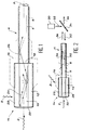
- Figure 1 there is shown schematically and partially a device according to the invention for the remote detection of radiation 2, such as X-ray or ⁇ radiation.
- radiation 2 such as X-ray or ⁇ radiation.
- the device of FIG. 1 comprises an optical fiber 4 whose core and optical sheath have the references 6 and 8 respectively.
- the optical fiber 4 has a large digital aperture, for example of the order of 0.43 ( ⁇ 25 °).
- the device of FIG. 1 also includes a detector crystal 10, one end of which is optically coupled to the optical fiber 4.
- the device of FIG. 1 further comprises an optical cladding 12 (“optical cladding”) which surrounds the detector crystal 10, which is in optical contact with it and whose optical index is lower than that of the detector crystal.
- optical cladding 12 optical cladding
- This detector crystal 10 is made of an inorganic material, which strongly absorbs radiation incident and which from this point of view is more favorable than a plastic.
- the detector crystal 10 is capable of emitting, by interaction, with the incident radiation 2, a light which then propagates in the optical fiber 4.
- the detector crystal 10 has the shape of a bar whose transverse dimensions, counted perpendicular to the axis X of the end of the fiber 4 to which this bar is optically coupled, are substantially equal to those of the core of the optical fiber 4, also counted perpendicular to the X axis.
- an optical fiber with symmetry of revolution around the axis X is used and a bar also with symmetry of revolution around this axis X and having substantially the same radius as the core of the fiber 4, this radius being much less than the length of the bar (which is counted parallel to the X axis).
- the detector element 14 makes it possible, thanks to the sheath 12, to keep the quantity of light collected by the optical fiber 4 substantially constant over the entire detection length which is the length of the detector crystal 10.
- this quantity of light collected remains constant whatever the position of point P of the detector crystal 10, point at which light is emitted by interaction of the crystal with the radiation.
- This provides a detection device having a good sensitivity for dosimetry, that is to say having a sufficient effective mass, due to the material of the detector crystal, the large aperture of the optical fiber and the optical sheath.
- the detector crystal 10 is made of a scintillating inorganic material such as for example bismuth germanate, sodium iodide, calcium or cadmium tunstanate, cesium fluoride, fluoride calcium or lithium iodide.
- a scintillating inorganic material such as for example bismuth germanate, sodium iodide, calcium or cadmium tunstanate, cesium fluoride, fluoride calcium or lithium iodide.
- the optical sheath 12 which constitutes a transparent tube with a lower optical index than that of the detector crystal 10 and which is in optical contact with the latter, is made of a material whose physical and thermal properties are chosen as a function of those of the material constituting the detector crystal 10.
- the end of the optical fiber 4 can be fixed to the detector element 14 by appropriate mechanical means 16 or by means of a layer of optical adhesive 18 placed at the interface between the detector crystal 10 and the fiber 4 , as seen in Figure 1.
- This adhesive is used both to fix the detector element to the fiber and to ensure the optical coupling between the detector crystal 10 and the core 6 of the fiber.
- Layer 20 is for example a 100 nm layer of aluminum deposited under vacuum.
- optical index of the detector crystal 10 and the optical index of the sheath 12 which is associated with it so that the digital aperture of the detector element 14 is slightly less than that of the optical fiber 4.
- the external wall of the optical sheath 12 with a layer 22 capable of absorbing the light emitted by interaction of the crystal with the radiation, at angles greater than the opening determined by the limiting angle. total reflection on the face common to the crystal and its optical sheath.
- the total reflection angle 26 of the fiber 4 is shown in dotted lines and it is seen, in the case of FIG. 1, that the total reflection limit angle relative to the detector element 14 is less than this limit angle 26.
- the device according to the invention which is schematically and partially shown in Figure 2 differs from that of Figure 1 in that, in the detector element 14 of the device of Figure 2, the detector crystal 28 is made of '' an inorganic material with optically stimulated luminescence.
- a source 30 of stimulation radiation 32 and a dichroic mirror 34 are used, allowing the injection of this stimulation radiation 32 into the end of the optical fiber 4, opposite to that which is optically coupled to the detector crystal. 28.
- optically stimulable luminescence material it is possible to use, for example, doped sulphides or doped glasses (silica, oxides such as, for example, germanium oxide, optical glasses, fluorinated glasses).
- doped sulphides or doped glasses silicon, oxides such as, for example, germanium oxide, optical glasses, fluorinated glasses.
- the dopants can be chosen from the group of rare earths.
- Elements with metastable energy levels can be samarium or europium for example.
- the detection efficiency remains at the maximum value (limited by the digital aperture of the optical fiber) over the entire length of the bar.
- the gain in sensitivity of such a radiation detection device is proportional to the useful length (length of the bar).
- a length of the order of 10 mm saves more than an order of magnitude in sensitivity compared to the device described in this document (4).
- a device according to the invention can be manufactured using a high melting temperature tube, for example made of silica, which is dipped in a bath of molten scintillating material.
- a bar of inorganic scintillating material NaI (Tl), CsI, BGO for example
- Such a device constitutes a very interesting detector for optical fiber dosimetry.
- this crystal and this sheath materials having similar thermal expansion coefficients.
- a detector crystal can be obtained in an optical sheath by an injection, pressure or stretching process if the material constituting the detector crystal supports fusion (followed by cooling) without loss of its properties.
- the material constituting the optical cladding can be silica or a glass of suitable optical index and of mechanical and thermal properties chosen as a function of the characteristics of the detector crystal which it is desired to associate with it.
- inorganic scintillating crystals Due to their higher density, inorganic scintillating crystals have a better capacity for detecting ⁇ radiation than organic scintillators.
- the energy deposited is greater (for electrons, the energy deposition per centimeter is 2.5 times higher for NaI than for a plastic scintillator material) and the light efficiency, for the same deposited energy, is four times higher.
- optical sheath associated with the detector crystal also constitutes protection, for example with respect to humidity.
- the performance of a detection device according to the invention is much higher than that of known devices comprising optical fibers, thanks to the use of the optical sheath around the detector crystal.
- the invention makes it possible to reach sensitivities in dose measurement of the order of 10 ⁇ Sv / h, or even 1 ⁇ Sv / h, which makes it possible to use it for making measurements which are impossible to carry out with known devices.
- dosimetry measurements can be carried out in real time for workers in the nuclear field, for example at particularly exposed extremities such as the hands and feet and also at sensitive organs.
- the transmission of the measurement signal by optical fiber makes it possible to access real-time information on the dose received and therefore to follow the evolution of the risk during work.
- devices according to the invention can be used for remote monitoring of sites and a large number of measurement points can be associated with a single information processing system, which is usually the most expensive part of measuring equipment.
Landscapes
- Physics & Mathematics (AREA)
- Health & Medical Sciences (AREA)
- Life Sciences & Earth Sciences (AREA)
- General Physics & Mathematics (AREA)
- High Energy & Nuclear Physics (AREA)
- Molecular Biology (AREA)
- Spectroscopy & Molecular Physics (AREA)
- Measurement Of Radiation (AREA)
- Light Guides In General And Applications Therefor (AREA)
Applications Claiming Priority (2)
| Application Number | Priority Date | Filing Date | Title |
|---|---|---|---|
| FR9404641 | 1994-04-19 | ||
| FR9404641A FR2718852B1 (fr) | 1994-04-19 | 1994-04-19 | Dispositif de détection à distance de rayonnement. |
Publications (1)
| Publication Number | Publication Date |
|---|---|
| EP0678757A1 true EP0678757A1 (de) | 1995-10-25 |
Family
ID=9462240
Family Applications (1)
| Application Number | Title | Priority Date | Filing Date |
|---|---|---|---|
| EP95400848A Withdrawn EP0678757A1 (de) | 1994-04-19 | 1995-04-14 | Verfahren zur Messung der Entfernung einer Strahlung |
Country Status (5)
| Country | Link |
|---|---|
| US (1) | US5640017A (de) |
| EP (1) | EP0678757A1 (de) |
| JP (1) | JPH0843535A (de) |
| CA (1) | CA2146195A1 (de) |
| FR (1) | FR2718852B1 (de) |
Cited By (2)
| Publication number | Priority date | Publication date | Assignee | Title |
|---|---|---|---|---|
| WO1997021112A3 (de) * | 1995-12-02 | 1997-08-21 | Forschungszentrum Juelich Gmbh | Sensor zur messung einer gewebeäquivalenten strahlendosis |
| WO2007011214A1 (en) * | 2005-07-19 | 2007-01-25 | Milabs B.V. | Radiation detection apparatus |
Families Citing this family (16)
| Publication number | Priority date | Publication date | Assignee | Title |
|---|---|---|---|---|
| US5809199A (en) * | 1995-09-21 | 1998-09-15 | Infrared Fiber Systems, Inc. | Biocompatible optical fiber tip for in vivo laser surgery |
| JP3591275B2 (ja) * | 1998-02-20 | 2004-11-17 | 株式会社日立製作所 | 放射線強度計測装置 |
| US6479829B1 (en) * | 1999-02-26 | 2002-11-12 | Agency Of Japan Atomic Energy Research Institute | Apparatus and method for detecting radiation that uses a stimulate phosphor |
| FR2826733B1 (fr) * | 2001-07-02 | 2003-09-05 | Commissariat Energie Atomique | Capteur de rayonnement, a compensation d'energie et grande ouverture angulaire, pour la dosimetrie a distance, et dispositif de dosimetrie utilisant ce capteur |
| GB0217538D0 (en) * | 2002-07-30 | 2002-09-11 | Mbda Uk Ltd | An optical fibre |
| US7038211B2 (en) * | 2002-12-03 | 2006-05-02 | Universities Research Association, Inc. | Systems and methods for detecting x-rays |
| US7279120B2 (en) | 2003-09-04 | 2007-10-09 | Intematix Corporation | Doped cadmium tungstate scintillator with improved radiation hardness |
| UA77423C2 (en) * | 2004-02-06 | 2006-12-15 | Inst Scintillation Materials O | Scintillation material based on activated lithium iodide crystal |
| WO2007085060A1 (en) | 2006-01-30 | 2007-08-02 | The University Of Sydney | Fibre optic dosimeter |
| US8044356B2 (en) * | 2006-11-13 | 2011-10-25 | Kabushiki Kaisha Toshiba | Survey meter |
| US20090015814A1 (en) | 2007-07-11 | 2009-01-15 | Carl Zeiss Smt Ag | Detector for registering a light intensity, and illumination system equipped with the detector |
| GB2472574A (en) * | 2009-08-10 | 2011-02-16 | Nat Nuclear Lab Ltd | Radiation Detector |
| JPWO2021085401A1 (de) * | 2019-10-31 | 2021-05-06 | ||
| US12247937B2 (en) * | 2020-05-28 | 2025-03-11 | Ohio State Innovation Foundation | Optical fiber-based gamma calorimeter (OFBGC) |
| CN115058776B (zh) * | 2022-06-22 | 2023-11-03 | 同济大学 | 一种宽带隙氟钨酸氟碘酸盐中红外非线性光学晶体材料及其制备和应用 |
| US20240027633A1 (en) * | 2022-07-22 | 2024-01-25 | University Of Utah Research Foundation | Dose monitor for flash radiotherapy |
Citations (3)
| Publication number | Priority date | Publication date | Assignee | Title |
|---|---|---|---|---|
| US4788436A (en) * | 1986-12-24 | 1988-11-29 | Walter Koechner | Radiation sensitive optical fiber and detector |
| US4829180A (en) * | 1984-03-23 | 1989-05-09 | Fuji Photo Film Co., Ltd. | Radiation image read-out apparatus |
| US5168540A (en) * | 1990-09-12 | 1992-12-01 | Advanced Technology Materials Inc. | Scintillating articles and method of making the same |
Family Cites Families (9)
| Publication number | Priority date | Publication date | Assignee | Title |
|---|---|---|---|---|
| FR2533709B1 (fr) * | 1982-09-23 | 1985-10-18 | Commissariat Energie Atomique | Fibres optiques en matiere plastique, notamment scintillantes et leur procede de fabrication |
| US4631409A (en) * | 1984-04-03 | 1986-12-23 | Harshaw/Filtrol | Scintillator crystal having a highly reflective surface |
| US4658141A (en) * | 1984-04-03 | 1987-04-14 | Harshaw/Filtrol Partnership | Inorganic scintillator crystal having a highly reflective surface |
| US4935632A (en) * | 1985-09-23 | 1990-06-19 | Landus Inc. | Luminescent concentrator light source |
| US5030834A (en) * | 1987-12-01 | 1991-07-09 | Quantex Corporation | Fiber optic dosimeter system using electron trapping materials |
| JPH02266287A (ja) * | 1989-04-07 | 1990-10-31 | Shin Etsu Chem Co Ltd | 放射線検出器 |
| US5308986A (en) * | 1992-12-17 | 1994-05-03 | Nanoptics Incorporated | High efficiency, high resolution, real-time radiographic imaging system |
| JP3327602B2 (ja) * | 1992-12-28 | 2002-09-24 | 東北電力株式会社 | 放射線検出光伝送装置 |
| US5391878A (en) * | 1993-11-03 | 1995-02-21 | Rockwell International Corporation | Multiplexed fiber readout of scintillator arrays |
-
1994
- 1994-04-19 FR FR9404641A patent/FR2718852B1/fr not_active Expired - Lifetime
-
1995
- 1995-04-03 CA CA002146195A patent/CA2146195A1/en not_active Abandoned
- 1995-04-13 US US08/421,246 patent/US5640017A/en not_active Expired - Fee Related
- 1995-04-14 EP EP95400848A patent/EP0678757A1/de not_active Withdrawn
- 1995-04-18 JP JP7092874A patent/JPH0843535A/ja not_active Withdrawn
Patent Citations (3)
| Publication number | Priority date | Publication date | Assignee | Title |
|---|---|---|---|---|
| US4829180A (en) * | 1984-03-23 | 1989-05-09 | Fuji Photo Film Co., Ltd. | Radiation image read-out apparatus |
| US4788436A (en) * | 1986-12-24 | 1988-11-29 | Walter Koechner | Radiation sensitive optical fiber and detector |
| US5168540A (en) * | 1990-09-12 | 1992-12-01 | Advanced Technology Materials Inc. | Scintillating articles and method of making the same |
Cited By (4)
| Publication number | Priority date | Publication date | Assignee | Title |
|---|---|---|---|---|
| WO1997021112A3 (de) * | 1995-12-02 | 1997-08-21 | Forschungszentrum Juelich Gmbh | Sensor zur messung einer gewebeäquivalenten strahlendosis |
| US6041150A (en) * | 1995-12-02 | 2000-03-21 | Forschungszentrum Julich Gmbh | Multipass cavity sensor for measuring a tissue-equivalent radiation dose |
| WO2007011214A1 (en) * | 2005-07-19 | 2007-01-25 | Milabs B.V. | Radiation detection apparatus |
| US7964850B2 (en) | 2005-07-19 | 2011-06-21 | Milabs B.V. | Radiation detection apparatus |
Also Published As
| Publication number | Publication date |
|---|---|
| US5640017A (en) | 1997-06-17 |
| JPH0843535A (ja) | 1996-02-16 |
| FR2718852A1 (fr) | 1995-10-20 |
| FR2718852B1 (fr) | 1996-05-15 |
| CA2146195A1 (en) | 1995-10-20 |
Similar Documents
| Publication | Publication Date | Title |
|---|---|---|
| EP0678757A1 (de) | Verfahren zur Messung der Entfernung einer Strahlung | |
| EP0606176B1 (de) | Vorrichtung zum gleichzeitigen und selektiven Nachweis von Neutronen und Röntgen- oder Gamma-Photonen durch Abschwächung | |
| US6140651A (en) | Optically stimulated, fast neutron sensor and dosimeter and fiber-optic coupled fast neutron remote sensor and dosimeter | |
| US20120001075A1 (en) | Method to optimize the light extraction from scintillator crystals in a solid-state detector | |
| US6151769A (en) | Method of making a scintillator waveguide | |
| US7791046B2 (en) | High efficiency fiber-optic scintillator radiation detector | |
| JP7731961B2 (ja) | プラスチック波長シフトファイバおよびその作製方法 | |
| FR2877099A1 (fr) | Systeme de mesure de rayonnement | |
| US4885471A (en) | Ultraviolet radiometer | |
| EP1273931A1 (de) | Zur Ferndosimetrie fähiger Strahlungsdetektor mit Energiekompensation und weitwinkliger Öffnung | |
| Kalnins et al. | Radiation dosimetry using optically stimulated luminescence in fluoride phosphate optical fibres | |
| Atkinson et al. | Initial tests of a high resolution scintillating fibre (SCIFI) tracker | |
| JPH067160B2 (ja) | 放射線検出器 | |
| Tsutsumi et al. | Position-sensitive detectors based on redshifts in photoluminescence spectra | |
| JP5976429B2 (ja) | 放射線弁別検出器及びその製造方法 | |
| US7772558B1 (en) | Multi-layer radiation detector and related methods | |
| EP0423030A1 (de) | Radiolumineszierender Schirm mit verbessertem Qualitätsfaktor und räumlicher Auflösung für das Abbilden mittels X- oder gamma-Photonen | |
| EP0319080B1 (de) | Röntgenstrahl-Bildverstärkerröhre | |
| Ruchti et al. | Scintillating glass, fiber-optic plate detectors for active target and tracking applications in high energy physics experiments | |
| JP2001523383A (ja) | 薄膜による光電陰極の保護 | |
| GB2519326A (en) | Scintillating optical fiber | |
| GB2200984A (en) | Fire optic ionizing radiation detector | |
| SU1122113A1 (ru) | Волокно дл сцинтилл ционных годоскопов | |
| EP3968066A1 (de) | Wellenleiter, der eine optische multimode-faser umfasst und die geführten moden räumlich konzentrieren kann | |
| JP2001516888A (ja) | シンチレーション検出器、シンチレータ用屈折コーティング、および該コーティングの製造プロセス |
Legal Events
| Date | Code | Title | Description |
|---|---|---|---|
| PUAI | Public reference made under article 153(3) epc to a published international application that has entered the european phase |
Free format text: ORIGINAL CODE: 0009012 |
|
| AK | Designated contracting states |
Kind code of ref document: A1 Designated state(s): CH DE GB LI SE |
|
| 17P | Request for examination filed |
Effective date: 19960329 |
|
| 17Q | First examination report despatched |
Effective date: 19980430 |
|
| STAA | Information on the status of an ep patent application or granted ep patent |
Free format text: STATUS: THE APPLICATION IS DEEMED TO BE WITHDRAWN |
|
| 18D | Application deemed to be withdrawn |
Effective date: 19980911 |