EP0678954A1 - Appareillage de commutation blindé métallique à isolement gazeux - Google Patents
Appareillage de commutation blindé métallique à isolement gazeux Download PDFInfo
- Publication number
- EP0678954A1 EP0678954A1 EP94110057A EP94110057A EP0678954A1 EP 0678954 A1 EP0678954 A1 EP 0678954A1 EP 94110057 A EP94110057 A EP 94110057A EP 94110057 A EP94110057 A EP 94110057A EP 0678954 A1 EP0678954 A1 EP 0678954A1
- Authority
- EP
- European Patent Office
- Prior art keywords
- pole
- housing
- metal
- insulated switchgear
- busbar
- Prior art date
- Legal status (The legal status is an assumption and is not a legal conclusion. Google has not performed a legal analysis and makes no representation as to the accuracy of the status listed.)
- Granted
Links
Images

Classifications
-
- H—ELECTRICITY
- H02—GENERATION; CONVERSION OR DISTRIBUTION OF ELECTRIC POWER
- H02B—BOARDS, SUBSTATIONS OR SWITCHING ARRANGEMENTS FOR THE SUPPLY OR DISTRIBUTION OF ELECTRIC POWER
- H02B1/00—Frameworks, boards, panels, desks, casings; Details of substations or switching arrangements
- H02B1/20—Bus-bar or other wiring layouts, e.g. in cubicles, in switchyards
- H02B1/22—Layouts for duplicate bus-bar selection
-
- H—ELECTRICITY
- H02—GENERATION; CONVERSION OR DISTRIBUTION OF ELECTRIC POWER
- H02B—BOARDS, SUBSTATIONS OR SWITCHING ARRANGEMENTS FOR THE SUPPLY OR DISTRIBUTION OF ELECTRIC POWER
- H02B13/00—Arrangement of switchgear in which switches are enclosed in, or structurally associated with, a casing, e.g. cubicle
- H02B13/02—Arrangement of switchgear in which switches are enclosed in, or structurally associated with, a casing, e.g. cubicle with metal casing
- H02B13/035—Gas-insulated switchgear
Definitions
- the invention is based on a metal-encapsulated gas-insulated switchgear assembly according to the preamble of claim 1.
- Switchgear systems with vertical circuit breakers are known, which have a double busbar system.
- Such a switchgear is known, for example, from the trade journal "E and M", Volume 102, Issue 7/8, page 305, Figure 2.
- the pole axis of the circuit breakers is vertical and the circuit breakers are actuated from below.
- the polar axes lie in one plane.
- the busbar systems have busbar axes that lie in planes that extend parallel to the foundation surface and perpendicular to the plane in which the polar axes lie. From each circuit breaker pole leads to the associated busbars an elaborate metal encapsulated connector. These connectors point for each phase has a different length.
- a busbar isolator is provided between the end of the respective connecting piece facing the busbars and each of the busbars.
- the end of the respective connecting piece facing the busbars can be earthed by means of an earth electrode.
- the outlets or infeeds all leave the circuit breaker at a certain height.
- the connectors are also connected to the circuit breaker in the same plane parallel to the foundation surface. The pole housings of the circuit breaker are therefore all of the same design.
- Such a metal-enclosed gas-insulated switchgear requires a comparatively large amount of space because of the given geometry.
- the connectors to the busbars make the switchgear more expensive.
- the invention solves the problem of creating a metal-encapsulated gas-insulated switchgear which can be designed with simple means in such a way that it takes up a significantly smaller space.
- connection housings required in conventional gas-insulated switchgear assemblies which bridge the different distances between the circuit breaker poles and the busbars, are no longer required.
- the apparatus installed in the gas-insulated switchgear can be packed more densely.
- This metal-encapsulated gas-insulated switchgear assembly is provided with at least one busbar system, which has an axis spacing s, also with a circuit breaker, which has one pole axis per pole, at least one quenching chamber built into a pole housing and at least one connection for the associated busbar, which is located on a connecting axis and the polar axes of which are arranged perpendicular to a foundation and lie in a first plane.
- the gas-insulated switchgear each has an electrically conductive connecting part which extends along the connection axis and which connects the at least one connection of the respective pole to the at least one of the busbar systems, and also in each case one isolator arranged in the connection between the at least one busbar and the pole.
- the busbar axes of the at least one busbar system run parallel to the foundation surface and lie in at least one other level.
- the first plane, in which the pole axes lie, is arranged parallel to the at least one further plane, and the connections for the busbars lie on a diagonal.
- two busbar systems are each arranged in a second plane and in a third plane, and that the first plane, in which the pole axes lie, is arranged in the middle between the second and third planes.
- connection is connected to a connecting part which extends along the connecting axes running perpendicular to these planes, and that all these connecting parts have the same overall length.
- connections are arranged at different heights from pole to pole for the associated busbar, and these differences are achieved solely by modifications in the structure of the poles, without using separate and variable connecting parts.
- Each of the pole housings of a three-pole circuit breaker is each made up of a housing lower part equipped with the connections, at least one housing upper part and a housing cover, the housing cover being installed as the same part in each of the pole housings, and furthermore the housing lower part as the same part being installed at the bottom in each of the pole housings, but not in the same installation position.
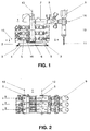
- FIG. 1 shows a schematically represented side view of an outgoing panel 1 of a single-phase metal-encapsulated gas-insulated switchgear and FIG. 2 shows a plan view of this outgoing panel 1.
- This outgoing panel 1 has a support frame 2 which is made from a metal profile. I-profiles or tubular profiles made of steel, for example, can be used as particularly suitable metal profiles. The tube profiles usually have a round or a rectangular cross section. At the corners of the support frame 2, angle profiles 3 are attached, which serve to connect the support frame 2 to a foundation 4. This connection can be designed to be non-positive, but it can also allow the support frame 2 to slide on a support rail embedded in the foundation 4 and not shown here.
- the busbars are 5 arranged vertically one above the other on one or on both sides of the vertically positioned poles of the circuit breaker 6.
- the outlet is provided with a current transformer 7, which is followed by a disconnector 8, which takes over the function of the outlet disconnector.
- An earth electrode is provided on each side of the disconnector 8.
- a voltage converter 9 is provided.
- a cable connection 10 connects the outgoing high-voltage cable 11 to the gas-insulated switchgear.
- a field provided for an infeed is designed similarly to the outgoing field 1 described.
- the busbars 5 each have a busbar axis 12.
- the busbar axes 12 of each of the two busbar systems lie vertically one above the other in one plane.
- the poles of the circuit breaker 6 each have a pole axis 13.
- the pole axes 13 of the three circuit breaker poles lie in a plane that is perpendicular to the foundation 4.
- the planes in which the busbar systems lie and the plane in which the pole axes 13 lie are arranged parallel to one another in this outgoing area 1.
- the part of the outgoing panel 1 leading away from the respective circuit breaker pole, the current transformer 7, the isolator 8 and the housing to which the cable connection 10 is flanged extends along a longitudinal axis 14.
- the longitudinal axis 14 is perpendicular to the respective pole axis 13. That of the circuit breaker 6 part of the outlet leading away can extend in the direction as shown in FIG. 1, but it can also extend in the opposite direction.
- the upper part of the pole housing which is made up of the upper housing part and the housing cover, can be aligned accordingly during assembly. As a rule, a rotation of 180 ° about the pole axis 13 is carried out, but it is also possible to turn the upper part of the pole housing by an angle in the range of 180 °. Since the circuit breaker 6 is provided with a separate drive per pole, each of the poles can have differently oriented outlets exhibit.
- connection from the respective circuit breaker pole to the busbars extends along a connection axis 15. From FIG. 1 it can be seen that in this outgoing panel 1 equipped with a double busbar system, only one earth electrode 16 is provided per connection. This gas-insulated switchgear saves one of the two earth electrodes that are normally required in this area, without sacrificing safety and without reducing the availability of the system. In a switchgear with a double busbar system, the earth electrode 16 can either be installed on one side or on the other side of the circuit breaker pole.
- control panel is set up as a dome panel
- the space provided on one side of the circuit breaker pole for the earth electrode is sufficient to seal the pole housing with a cover so that there is still enough space for the busbar, so that the busbar axis 12 remains unchanged even in a dome panel can be maintained compared to the dining and departure areas.
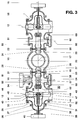
- FIG. 3 shows a schematic representation of the section AA entered in FIG.
- the polar axis 13 is perpendicular on the cutting plane, it pierces it at a central point 17.
- a cylindrically shaped lower housing part 18, which extends along the pole axis 13, is provided with two openings (not designated) lying on the connecting axis 15 as the center, each with a cylindrically shaped, disk-shaped partition insulator 19, 20 are flanged in a pressure-tight manner.
- the bulkhead insulator 19 has a current connection 21 penetrating it in the center.
- the bulkhead isolator 20 has a power connection 22 penetrating it in the center.
- the connecting piece 23 is firmly screwed to a contact ring 25 made of an electrically highly conductive metal.
- the connecting piece 23 and the contact ring 25 can also be formed in one piece.
- the contact ring 25 has a contact arrangement 26 screwed to it on the side opposite the connecting piece 23.
- the power connection 21 is connected to a contact carrier 27, which is equipped, for example, with spiral contacts.
- the contact arrangement 26 encloses the contact carrier 27 and forms with it a detachable plug contact which is surrounded by a dielectrically designed shield 28.
- the center of the contact ring 25 coincides with the central point 17.
- the cylindrical inner surface of the contact ring 25 is provided with at least one groove, not shown, into which a plastic ring, not shown, is glued.
- the plastic ring guides the electrically conductive exhaust housing of the same, which is equipped on the outside with elastic contact elements, for example with spiral contacts, which make electrical contact with the contact ring 25, and prevents the elastic contact elements from being subjected to an asymmetrical mechanical load become.
- the inner opening of the contact ring 25 is completely closed by the exhaust housing connected to the arcing chamber.
- the housing 29 of a separator 30 designed as an angle separator is flanged in a pressure-tight manner.
- the housing 29 of the separator 30, shown in simplified form, has a wall made of metal. As a rule, the housing 29 is cast pressure-tight from an aluminum alloy. In addition to the opening closed by the partition isolator 19, the housing 29 has five further openings (not designated) provided with flanges 31 to 35. The housing 29 also has a longitudinal axis which coincides with the connecting axis 15.
- the opening provided with the flange 31 is provided with a metallic cover 36 during assembly of the isolator, which has a flange 37 which is screwed to the flange 31 in a gas-tight manner. Another flange 38 is attached to the cover 36 opposite the flange 37.
- the flange 38 is used to fasten a pressure-resistant bushing for an isolating rod 39 which can be moved in the direction of an actuating axis coinciding with the connecting axis 15 when the isolator 30 is switched.
- the isolating rod 39 moves, driven by an isolating drive 40 which is also connected to the flange 38, and which is strong Movable contact arrangement 41 of the isolator 30, shown schematically.
- the movable contact arrangement 41 is surrounded by a dielectric shield 42 which is penetrated by the insulating rod 39.
- a busbar housing (not shown) is flanged to the flange 32.
- a bulkhead insulator 43 is flanged to the flange 33 and is penetrated by a power connection 44.
- a conductor piece 45 is screwed to the power connection 44, which is insulator-side of a dielectric shield 46 is encased.
- the conductor piece 45 extends along the busbar axis 12, which runs perpendicular to the connecting axis 15.
- the conductor piece 45 is electrically conductively connected to a first fixed contact carrier 47 of the isolator 30.
- a sliding contact 48 is embedded in the contact carrier 47 and is provided for the current transfer from the movable contact arrangement 41 of the isolator 30 to the contact carrier 47.
- the sliding contact 48 is arranged concentrically to the connecting axis 15, it is provided with contact fingers, with contact lamellae or with spiral contacts.
- the contact carrier 47 is arranged concentrically with the connecting axis 15.
- the contact carrier 47 is simultaneously formed as part of the active busbar parts.
- the power connection 21 is electrically conductively connected to a second fixed contact carrier 50 of the isolator 30.
- the insulator-side end of the contact carrier 50 is covered with a dielectric shield 51.
- the end of the contact carrier 50 facing the contact carrier 47 is provided with a counter contact 52 arranged concentrically with the connecting axis 15 for the movable contact arrangement 41 of the isolator 30.
- the contact carriers 47 and 50 have a dielectric design, and any edges are rounded.
- the power connections 44 and 21 are at high voltage potential during operation and are insulated from the metal encapsulation of the gas-insulated switchgear.
- a tulip-shaped counter contact 53 is embedded in the contact carrier 50, which is arranged concentrically to an installation axis 54 and which receives the contact pin 55 of the earth 16 when the earth 16 is closed.
- the installation axis 54 is perpendicular to the connection axis 15.
- the movable contact arrangement 41 When the isolator 30 is switched on, the movable contact arrangement 41 is moved along the connecting axis 15 towards the counter contact 52 by the isolating rod 39 actuated by the isolator drive 40.
- a pre-ignition between the movable contact arrangement 41 and the counter contact 52 which is possibly caused by residual charges and / or by an operating frequency voltage present between the contact carrier 47 and the counter contact 52, is controlled perfectly by the isolator 30.
- An expansion of the pre-ignition arc towards the wall of the housing 29 cannot occur due to the geometric arrangement of the contact carrier 47 and the counter-contact 52.
- the disconnector drive 40 is designed in such a way that it moves the movable contact arrangement 41 securely into the intended switch-on position in every possible operating case, so that a faultless current supply is ensured via the nominal current contacts provided for this purpose, which are not described in more detail. Likewise, the opening of the separator 30 is always carried out correctly.
- the earth electrode 16 is installed in the opening provided with the flange 34.
- it could alternatively be installed in the opening provided with the flange 35.
- Detectors for monitoring the gas-insulated switchgear or, as shown in FIG. 3, a rupture disk 57 can be flanged to the flange 35 in a pressure-tight manner, which enables the housing 29 to be relieved of pressure in the event of a fault.
- the two flanges 34 and 35 have a common installation axis 54.
- the housing 58 flanged on the other side of the lower housing part 18 corresponds to the housing 29 with almost all built-in parts, it is only arranged in a mirror image of the latter and no earth electrode is installed.
- the mating contact of the earth wire has not been installed.
- a contact carrier 62 which carries a mating contact 63 of the isolator arranged on the right, is electrically conductively connected to the power connection 22 on the side facing away from the connecting piece 23.
- the isolator 30 can be installed in any installation position that is specified by the system concept of the metal-encapsulated gas-insulated switchgear.
- the earth electrode 16 can also be actuated independently of the position, so that there are therefore no installation restrictions.
- the earth electrode 16 can be designed both as a working earth electrode and as a fast earth electrode.
- the isolator assembly 30 with the earth electrode 16 connected upstream is very compact and takes up very little space in the direction of the connecting axis 15, so that the control panel can be designed with particularly small dimensions.
- the open isolating section of the isolator is insulated extremely reliably using SF6.
- the isolator When disconnected, the isolator has an optimal nominal current carrying capacity, a very good short-circuit current carrying capacity and surge current resistance. It also has a reliable switching capacity with small ones capacitive currents, it also masters switching when there is an uninterrupted busbar change.
- the isolator 30 has separate contact systems for the continuous current supply and for the actual switching process.
- the permanent current contacts are simple and reliable, they have a minimal number of individual parts.
- the contact movement takes place by means of an electrically operated disconnector drive, which is arranged outside the separator housing filled with SF6 gas, but the disconnector can also be driven by hand.
- Such a configuration advantageously facilitates maintenance work.
- the isolator is equipped with a mechanically coupled position indicator, and a sight glass can be provided for an endoscope to check the position of the contacts.
- FIG. 4 shows a greatly simplified schematic representation of the section BB entered in FIG. 2 through a first pole of the circuit breaker 6.
- This pole has a metallic pole housing filled with insulating gas, which is composed of several components which are connected to one another in a pressure-tight manner.
- the pole housing has a lower housing part 18 which is closed at the bottom by a cover flange 64 and which is of the same design in all three poles of a three-pole circuit breaker 6, but which is used in a different installation position.
- a contacting assembly 65 is installed in the lower housing part 18. This contacting assembly 65 consists in each case of the parts described in connection with FIG. 3, such as the connecting piece 23 with the shield 24, the contact ring 25, the contact arrangement 26 and the contact carrier 27 with the shield 28.
- the contacting assembly 65 is on the one hand connected to the power connection 21 of the Bulkhead insulator 19 pluggable and on the other hand firmly connected to the power connection 22 of the bulkhead insulator 20.
- the circuit breaker pole has an arcing chamber 66 which has a cylindrical exhaust pipe 67 made of metal and arranged concentrically to the pole axis 13, which is inserted into the contacting assembly 65 and is connected to it in an electrically conductive manner via sliding contacts such as spiral contacts.
- the exhaust housing 67 transmits the potential of the contacting assembly 65 to the lower part of the arcing chamber 66 and at the same time carries the operating current when the circuit breaker pole is closed.
- An upper housing part 68 is placed on the lower housing part 18 and has an opening, not designated, which is closed in a pressure-tight manner with a partition insulator 69.
- the bulkhead insulator 69 has a current connection 70 penetrating it, which on the one hand is electrically conductively connected to the active parts of the outlet, not shown, which extend in the direction of the longitudinal axis 14, and on the other hand is connected to the upper part 72 of the arcing chamber 66 via a knife contact 71 is.
- the upper part 72 and the lower part of the arcing chamber 66 are connected to one unit by an arcing chamber insulator 73.
- the arcing chamber insulator 73 insulates the upper part 72 from the lower part when the circuit breaker pole is switched off.
- the arcing chamber 66 is connected to a housing cover 75 by means of a holding insulator 74 and is held by this in the center of the pole housing.
- the housing cover 75 is connected to the upper housing part 68 and closes off the pole housing from above.
- the housing cover 75 is provided with a rupture disk 76 which, in an emergency, allows excess pressure which arises in the pole housing to escape into the environment.
- a drive 77 for the circuit breaker pole is flanged to the housing cover 75.
- the drive 77 is not located on the pole axis 13, it is arranged next to the pole housing, specifically on the opposite end to the cable connection 10 Side of the pole housing. The overall height of the circuit breaker pole is thus not, or only insignificantly, increased by the drive 77.
- the drive 77 acts via a schematically indicated force conversion on an insulating actuating rod 78, which moves the movable contact parts of the arcing chamber 66 along the polar axis 13.
- the extinguishing chamber 66 hanging on the housing cover 75 is inserted into the pole housing from above in such a way that the exhaust housing 67 makes perfect contact with the contacting assembly 65, and that the knife contact 71 also reliably connects the active parts of the outlet with the upper part 72 of the extinguishing chamber 66 electrically connects.
- FIG. 5 shows a schematic representation of the section CC entered in FIG. 2 through a second circuit breaker pole.
- This circuit breaker pole also has a metallic pole housing filled with insulating gas, which is composed of several components which are connected to one another in a pressure-tight manner.
- the longitudinal axis 14 of the outlet is at the same level with this pole as with the pole described above.
- This pole housing has a lower housing part 18 which is closed at the bottom by a cover flange 64 and which is of identical design in all three poles of the three-pole circuit breaker 6. Here it is installed in the same installation position as in the pole according to FIG. 4.
- the same contacting assembly 65 is installed in the lower housing part 18 here.
- the contacting assembly 65 establishes the electrically conductive connection to an exhaust housing 79.
- the lower housing part 18 is connected to an upper housing part 80.
- the upper housing part 80 is compared to the corresponding upper housing part 68 in Figure 4 and the exhaust housing 79 is compared to the corresponding exhaust housing 67 in Figure 4 each shortened by the same dimension s.
- the dimension s corresponds to the vertical center distance of the busbars 5.
- the other components of the Both switch poles of the circuit breaker 6 are of the same design.
- the shortening of the mentioned components by the dimension s has the consequence that the circuit breaker pole according to FIG. 5 is shorter by precisely this dimension s, and that the busbar connection of this pole, which extends along a connection axis 81, is around the dimension relative to the connection axis 15 s is shifted upwards.
- FIG. 6 shows a schematic representation of the section D-D entered in FIG. 2 through a third pole of the circuit breaker 6.
- This circuit breaker pole has a metallic pole housing filled with insulating gas, which is composed of several components which are connected to one another in a pressure-tight manner.
- the longitudinal axis 14 of the outlet is at the same level with this pole as with the two poles described above.
- the pole housing has a lower housing part 18 closed at the bottom with a cover flange 64, which is of exactly the same design in all three poles of the three-pole circuit breaker 6, but which is used in this pole, however, rotated by 180 ° with respect to the installation position in the other two circuit breaker poles.
- a contacting assembly 65 is installed in the lower housing part 18. This pole is also shorter than the pole according to FIG. 4 by the dimension s.
- connection axis 82 points to the longitudinal axis 14, which is arranged at the same height in all three circuit breaker poles, a distance that corresponds to the dimension s.
- the pole according to FIG. 4 is attached to the support frame 2.
- the other two poles both of which are shorter by the dimension s, are mounted on a platform connected to the support frame 2, which is so high that the mentioned difference in dimensions is compensated for.
- the pedestal is welded from profiled iron, it is very inexpensive and can be created with little effort.
- the upper housing part 68 extended by the dimension s and the exhaust housing 67 also extended by the dimension s, no further modified components are necessary in order to use the differently long and complex connecting pieces between the circuit breaker poles and in a conventionally constructed metal-encapsulated gas-insulated switchgear to make the busbars assigned to them superfluous.
- the pole axes 13 are arranged in one plane.
- the pole axes 13 run perpendicular to the foundation 4.
- the busbar axes 12 of a busbar system are likewise arranged in a plane perpendicular to the foundation 4, but the busbar axes 12 run parallel to the surface of the foundation 4. If a gas-insulated switchgear system with only one busbar system is created, it can be done this can be arranged either on one or on the other side of the plane of the pole axes 13 of the circuit breaker 6. For special applications, it is also possible to guide only one of the system busbars on the opposite side of the plane of the pole axes 13.
- the busbar systems are generally arranged on both sides of the plane of the pole axes 13 of the circuit breaker 6 and at the same distance from it.
- a particularly compact arrangement of the gas-insulated switchgear system is obtained if the distance between adjacent busbar axes 12, which corresponds to dimension s, is chosen to be the same size as the distance between adjacent pole axes 13.
- the connecting line between the connecting axes 15, 81 and 82 then has an angle of 45 ° with respect to the direction of the busbar axes 12.
Landscapes
- Engineering & Computer Science (AREA)
- Power Engineering (AREA)
- Gas-Insulated Switchgears (AREA)
Applications Claiming Priority (2)
| Application Number | Priority Date | Filing Date | Title |
|---|---|---|---|
| CH1218/94 | 1994-04-19 | ||
| CH121894 | 1994-04-19 |
Publications (2)
| Publication Number | Publication Date |
|---|---|
| EP0678954A1 true EP0678954A1 (fr) | 1995-10-25 |
| EP0678954B1 EP0678954B1 (fr) | 1998-09-02 |
Family
ID=4205259
Family Applications (1)
| Application Number | Title | Priority Date | Filing Date |
|---|---|---|---|
| EP94110057A Expired - Lifetime EP0678954B1 (fr) | 1994-04-19 | 1994-06-29 | Appareillage de commutation blindé métallique à isolement gazeux |
Country Status (7)
| Country | Link |
|---|---|
| US (1) | US5589674A (fr) |
| EP (1) | EP0678954B1 (fr) |
| CN (1) | CN1041152C (fr) |
| BR (1) | BR9501712A (fr) |
| CA (1) | CA2145455A1 (fr) |
| DE (1) | DE59406834D1 (fr) |
| ZA (1) | ZA952119B (fr) |
Cited By (2)
| Publication number | Priority date | Publication date | Assignee | Title |
|---|---|---|---|---|
| EP0688071B1 (fr) * | 1994-06-13 | 1999-08-18 | Asea Brown Boveri Ag | Appareillage de commutation blindé métallique à gaz isolant |
| US5991148A (en) * | 1997-04-17 | 1999-11-23 | Asea Brown Boveri Ag | Metal-enclosed gas-insulated switchgear assembly |
Families Citing this family (15)
| Publication number | Priority date | Publication date | Assignee | Title |
|---|---|---|---|---|
| DE4438776C1 (de) * | 1994-10-21 | 1996-04-11 | Siemens Ag | Metallgekapselte elektrische Hochspannungsschaltanlage mit einem Leistungsschalter |
| CN1323459A (zh) * | 1998-10-13 | 2001-11-21 | 株式会社日立制作所 | 气体绝缘开关装置 |
| ES2234402B1 (es) * | 2003-06-03 | 2006-10-16 | Red Electrica De España, S.A. | Subestacion electrica. |
| EP1667293B1 (fr) * | 2003-06-03 | 2010-10-13 | Red Eléctrica de Espana S.A. | Sous-station electrique |
| CN101300720B (zh) * | 2006-03-31 | 2011-08-24 | 三菱电机株式会社 | 气体绝缘电力设备 |
| DE102007047200A1 (de) * | 2007-05-31 | 2008-12-04 | Abb Technology Ag | Hochspannungsschaltanlage |
| CN101861688B (zh) * | 2007-11-29 | 2013-03-13 | 三菱电机株式会社 | 气体绝缘开关装置 |
| US9560953B2 (en) | 2010-09-20 | 2017-02-07 | Endochoice, Inc. | Operational interface in a multi-viewing element endoscope |
| FR2984617B1 (fr) * | 2011-12-14 | 2014-11-28 | Alstom Technology Ltd | Coude a angles d'orientation multiples pour lignes a haute tension |
| JP5875466B2 (ja) * | 2012-05-31 | 2016-03-02 | 株式会社日立製作所 | スイッチギヤまたはスイッチギヤの組立方法 |
| DE102018213934A1 (de) * | 2018-08-17 | 2020-02-20 | Siemens Aktiengesellschaft | Mehrphasige Schaltanlage |
| CN112086895B (zh) * | 2019-06-13 | 2022-07-29 | 河南平芝高压开关有限公司 | 断路器静端连接组件、双母线断路器及gis |
| CN112909749A (zh) * | 2021-01-14 | 2021-06-04 | 河南平高电气股份有限公司 | Gis母线的导电杆组件 |
| TR2022001937A2 (tr) * | 2022-02-14 | 2022-02-21 | Europower Enerji Ve Otomasyon Teknolojileri Sanayi Ticaret Anonim Sirketi | Metal plakalar sayesi̇nde bi̇rbi̇ri̇nden ayrilabi̇len orta geri̇li̇m şalt si̇stemleri̇nde kullanimi amaçlanan moduler ve dönüştürülebi̇li̇r i̇zolasyon kutbu |
| CN114865520B (zh) * | 2022-05-19 | 2024-06-28 | 中国南方电网有限责任公司超高压输电公司昆明局 | 气体绝缘金属封闭开关设备及其检测系统 |
Citations (6)
| Publication number | Priority date | Publication date | Assignee | Title |
|---|---|---|---|---|
| GB844098A (en) * | 1957-04-01 | 1960-08-10 | Coq Nv | Improvements in and relating to metal-clad switch-gear |
| FR1440652A (fr) * | 1964-12-31 | 1966-06-03 | Coq France | Installation de postes électriques blindés |
| DE2540058A1 (de) * | 1975-09-09 | 1977-03-17 | Bbc Brown Boveri & Cie | Metallgekapselte, druckgasisolierte hochspannungsschaltanlage |
| DE3034021A1 (de) * | 1980-09-10 | 1982-03-25 | Wilhelm Ritter GmbH & Co, 4600 Dortmund | Elektrische schaltanlage |
| EP0175159A1 (fr) * | 1984-09-04 | 1986-03-26 | Siemens Aktiengesellschaft | Appareillage électrique de commutation tripolaire |
| EP0563535A1 (fr) * | 1992-04-01 | 1993-10-06 | Felten & Guilleaume Energietechnik AG | Installation de commutation à blindage métallique isolée par SF6 avec jeu de barres omnibus |
Family Cites Families (7)
| Publication number | Priority date | Publication date | Assignee | Title |
|---|---|---|---|---|
| CH387743A (de) * | 1961-06-30 | 1965-02-15 | Bbc Brown Boveri & Cie | Metallgekapselte Schaltanlage in Doppelfeldbauweise |
| NL140670B (nl) * | 1969-11-05 | 1973-12-17 | Coq Nv | Geheel gesloten schakelinrichting voor hoge spanning met pen-busverbinding tussen kabelaansluiting en scheidingsschakelaar. |
| US3787604A (en) * | 1972-10-27 | 1974-01-22 | Ite Imperial Corp | Conductor support for transition from gas bus enclosure tube to power circuit breaker |
| NL158330B (nl) * | 1975-02-13 | 1978-10-16 | Coq Bv | Geheel gesloten eenfase schakeldveld voor hoge spanning. |
| FR2594607B1 (fr) * | 1986-02-14 | 1988-04-29 | Merlin Gerin | Poste blinde subdivise en compartiments etanches |
| CH675175A5 (fr) * | 1987-10-27 | 1990-08-31 | Bbc Brown Boveri & Cie | |
| JPH0727748B2 (ja) * | 1989-07-05 | 1995-03-29 | 株式会社日立製作所 | ガス絶縁開閉装置 |
-
1994
- 1994-06-29 DE DE59406834T patent/DE59406834D1/de not_active Expired - Lifetime
- 1994-06-29 EP EP94110057A patent/EP0678954B1/fr not_active Expired - Lifetime
-
1995
- 1995-03-15 ZA ZA952119A patent/ZA952119B/xx unknown
- 1995-03-24 CA CA002145455A patent/CA2145455A1/fr not_active Abandoned
- 1995-03-29 US US08/412,926 patent/US5589674A/en not_active Expired - Lifetime
- 1995-04-18 BR BR9501712A patent/BR9501712A/pt not_active Application Discontinuation
- 1995-04-18 CN CN95105060A patent/CN1041152C/zh not_active Expired - Fee Related
Patent Citations (6)
| Publication number | Priority date | Publication date | Assignee | Title |
|---|---|---|---|---|
| GB844098A (en) * | 1957-04-01 | 1960-08-10 | Coq Nv | Improvements in and relating to metal-clad switch-gear |
| FR1440652A (fr) * | 1964-12-31 | 1966-06-03 | Coq France | Installation de postes électriques blindés |
| DE2540058A1 (de) * | 1975-09-09 | 1977-03-17 | Bbc Brown Boveri & Cie | Metallgekapselte, druckgasisolierte hochspannungsschaltanlage |
| DE3034021A1 (de) * | 1980-09-10 | 1982-03-25 | Wilhelm Ritter GmbH & Co, 4600 Dortmund | Elektrische schaltanlage |
| EP0175159A1 (fr) * | 1984-09-04 | 1986-03-26 | Siemens Aktiengesellschaft | Appareillage électrique de commutation tripolaire |
| EP0563535A1 (fr) * | 1992-04-01 | 1993-10-06 | Felten & Guilleaume Energietechnik AG | Installation de commutation à blindage métallique isolée par SF6 avec jeu de barres omnibus |
Non-Patent Citations (1)
| Title |
|---|
| WILLI J. SCHMITT ET AL.: "Vollgekapselte, SF6-isolierte 110-kV-Schaltanlagen in der Energieversorgung", BBC-NACHRICHTEN, vol. 53, no. 1/2, February 1971 (1971-02-01), pages 3 - 14, XP001456793 * |
Cited By (3)
| Publication number | Priority date | Publication date | Assignee | Title |
|---|---|---|---|---|
| EP0688071B1 (fr) * | 1994-06-13 | 1999-08-18 | Asea Brown Boveri Ag | Appareillage de commutation blindé métallique à gaz isolant |
| US5991148A (en) * | 1997-04-17 | 1999-11-23 | Asea Brown Boveri Ag | Metal-enclosed gas-insulated switchgear assembly |
| DE19716024B4 (de) * | 1997-04-17 | 2007-01-18 | Abb Schweiz Ag | Metallgekapselte gasisolierte Schaltanlage |
Also Published As
| Publication number | Publication date |
|---|---|
| CN1120754A (zh) | 1996-04-17 |
| ZA952119B (en) | 1995-12-11 |
| CN1041152C (zh) | 1998-12-09 |
| US5589674A (en) | 1996-12-31 |
| DE59406834D1 (de) | 1998-10-08 |
| EP0678954B1 (fr) | 1998-09-02 |
| CA2145455A1 (fr) | 1995-10-20 |
| BR9501712A (pt) | 1995-11-14 |
Similar Documents
| Publication | Publication Date | Title |
|---|---|---|
| EP0688071B1 (fr) | Appareillage de commutation blindé métallique à gaz isolant | |
| EP0744803B1 (fr) | Sectionneur pour une installation de commutation à haute tension, blindé et à isolation gazeuse | |
| EP0291762B1 (fr) | Installation de commutation polyphasée haute tension blindée à isolation gazeuse | |
| EP0678954B1 (fr) | Appareillage de commutation blindé métallique à isolement gazeux | |
| EP0678955B1 (fr) | Appareillage de commutation blindé métallique à isolement gazeux | |
| EP0069693B1 (fr) | Container cylindrique pour une installation haute tension blindée tripolaire à isolation gazeuse | |
| EP1249910B1 (fr) | Disjoncteur haute-tension pour une installation de commutation à isolation gaseuse | |
| EP0152611B1 (fr) | Appareillage de commutation blindé métallique à gaz isolant | |
| EP0678952B1 (fr) | Sectionneur pour un appareillage de commutation blindé métallique à haute tension et à isolement gazeux | |
| EP3811475B1 (fr) | Appareillage de commutation multiphasé | |
| WO1999045617A1 (fr) | Installations de distribution electriques isolees aux gaz, sous enveloppe metallique, munies de recipients remplis de gaz | |
| EP0875971B1 (fr) | Installation de distribution électrique pour haute tension | |
| EP2054982A1 (fr) | Composant de raccordement muni d'un boitier de scellement | |
| EP1629581B1 (fr) | Systeme de disjoncteurs | |
| DE3521945A1 (de) | Trennschalter fuer eine metallgekapselte, druckgasisolierte hochspannungsschaltanlage | |
| EP0012708B1 (fr) | Dispositif de commutation polyphasé à blindage métallique, isolé par du gaz sous pression, pour installations de commutation à haute tension | |
| EP0678953B1 (fr) | Terminaison de câble pour un appareillage de commutation blindé métallique à haute tension et à isolement gazeux | |
| EP1629580B1 (fr) | Ensemble commutateur | |
| WO2004109882A2 (fr) | Composant de barre collectrice isole au gaz comprenant une traversee exterieure | |
| DE4438787C1 (de) | Metallgekapselte Hochspannungsschaltanlage mit einer dreipolig gekapselten Sammelschiene | |
| EP1825488B1 (fr) | Appareil de distribution polyphase dote d'au moins trois unites de coupure de meme type | |
| DE3329404C2 (fr) | ||
| EP0171352A1 (fr) | Installation de commutation haute tension blindée à isolation gazeuse | |
| DE19606213A1 (de) | Schaltfeld in einer elektrischen, metallgekapselten, gasisolierten Hochspannungsschaltanlage | |
| DE3034021A1 (de) | Elektrische schaltanlage |
Legal Events
| Date | Code | Title | Description |
|---|---|---|---|
| PUAI | Public reference made under article 153(3) epc to a published international application that has entered the european phase |
Free format text: ORIGINAL CODE: 0009012 |
|
| AK | Designated contracting states |
Kind code of ref document: A1 Designated state(s): CH DE FR GB IT LI NL |
|
| 17P | Request for examination filed |
Effective date: 19960329 |
|
| RAP1 | Party data changed (applicant data changed or rights of an application transferred) |
Owner name: ASEA BROWN BOVERI AG |
|
| 17Q | First examination report despatched |
Effective date: 19961227 |
|
| GRAG | Despatch of communication of intention to grant |
Free format text: ORIGINAL CODE: EPIDOS AGRA |
|
| GRAG | Despatch of communication of intention to grant |
Free format text: ORIGINAL CODE: EPIDOS AGRA |
|
| GRAH | Despatch of communication of intention to grant a patent |
Free format text: ORIGINAL CODE: EPIDOS IGRA |
|
| GRAH | Despatch of communication of intention to grant a patent |
Free format text: ORIGINAL CODE: EPIDOS IGRA |
|
| GRAA | (expected) grant |
Free format text: ORIGINAL CODE: 0009210 |
|
| AK | Designated contracting states |
Kind code of ref document: B1 Designated state(s): CH DE FR GB IT LI NL |
|
| PG25 | Lapsed in a contracting state [announced via postgrant information from national office to epo] |
Ref country code: NL Free format text: LAPSE BECAUSE OF FAILURE TO SUBMIT A TRANSLATION OF THE DESCRIPTION OR TO PAY THE FEE WITHIN THE PRESCRIBED TIME-LIMIT Effective date: 19980902 Ref country code: GB Free format text: LAPSE BECAUSE OF FAILURE TO SUBMIT A TRANSLATION OF THE DESCRIPTION OR TO PAY THE FEE WITHIN THE PRESCRIBED TIME-LIMIT Effective date: 19980902 |
|
| REG | Reference to a national code |
Ref country code: CH Ref legal event code: EP |
|
| REF | Corresponds to: |
Ref document number: 59406834 Country of ref document: DE Date of ref document: 19981008 |
|
| ET | Fr: translation filed | ||
| NLV1 | Nl: lapsed or annulled due to failure to fulfill the requirements of art. 29p and 29m of the patents act | ||
| GBV | Gb: ep patent (uk) treated as always having been void in accordance with gb section 77(7)/1977 [no translation filed] |
Effective date: 19980902 |
|
| PLBE | No opposition filed within time limit |
Free format text: ORIGINAL CODE: 0009261 |
|
| STAA | Information on the status of an ep patent application or granted ep patent |
Free format text: STATUS: NO OPPOSITION FILED WITHIN TIME LIMIT |
|
| 26N | No opposition filed | ||
| REG | Reference to a national code |
Ref country code: CH Ref legal event code: PFA Free format text: ASEA BROWN BOVERI AG TRANSFER- ABB SCHWEIZ HOLDING AG Ref country code: CH Ref legal event code: NV Representative=s name: ABB SCHWEIZ AG INTELLECTUAL PROPERTY (CH-LC/IP) |
|
| REG | Reference to a national code |
Ref country code: FR Ref legal event code: CD Ref country code: FR Ref legal event code: CA |
|
| REG | Reference to a national code |
Ref country code: CH Ref legal event code: PUE Owner name: ABB SCHWEIZ AG Free format text: ABB SCHWEIZ HOLDING AG#BROWN BOVERI STRASSE 6#5400 BADEN (CH) -TRANSFER TO- ABB SCHWEIZ AG#BROWN BOVERI STRASSE 6#5400 BADEN (CH) |
|
| REG | Reference to a national code |
Ref country code: FR Ref legal event code: TP |
|
| PGFP | Annual fee paid to national office [announced via postgrant information from national office to epo] |
Ref country code: CH Payment date: 20130621 Year of fee payment: 20 Ref country code: DE Payment date: 20130620 Year of fee payment: 20 |
|
| PGFP | Annual fee paid to national office [announced via postgrant information from national office to epo] |
Ref country code: IT Payment date: 20130625 Year of fee payment: 20 Ref country code: FR Payment date: 20130703 Year of fee payment: 20 |
|
| REG | Reference to a national code |
Ref country code: CH Ref legal event code: PL |
|
| REG | Reference to a national code |
Ref country code: DE Ref legal event code: R071 Ref document number: 59406834 Country of ref document: DE |
|
| PG25 | Lapsed in a contracting state [announced via postgrant information from national office to epo] |
Ref country code: DE Free format text: LAPSE BECAUSE OF EXPIRATION OF PROTECTION Effective date: 20140701 |