EP0679047A2 - Circuit pour l'alimentation pulsée d'une lampe à décharge - Google Patents
Circuit pour l'alimentation pulsée d'une lampe à décharge Download PDFInfo
- Publication number
- EP0679047A2 EP0679047A2 EP95104763A EP95104763A EP0679047A2 EP 0679047 A2 EP0679047 A2 EP 0679047A2 EP 95104763 A EP95104763 A EP 95104763A EP 95104763 A EP95104763 A EP 95104763A EP 0679047 A2 EP0679047 A2 EP 0679047A2
- Authority
- EP
- European Patent Office
- Prior art keywords
- circuit arrangement
- generator
- control
- voltage
- simmer
- Prior art date
- Legal status (The legal status is an assumption and is not a legal conclusion. Google has not performed a legal analysis and makes no representation as to the accuracy of the status listed.)
- Granted
Links
Images

Classifications
-
- H—ELECTRICITY
- H05—ELECTRIC TECHNIQUES NOT OTHERWISE PROVIDED FOR
- H05B—ELECTRIC HEATING; ELECTRIC LIGHT SOURCES NOT OTHERWISE PROVIDED FOR; CIRCUIT ARRANGEMENTS FOR ELECTRIC LIGHT SOURCES, IN GENERAL
- H05B41/00—Circuit arrangements or apparatus for igniting or operating discharge lamps
- H05B41/14—Circuit arrangements
- H05B41/26—Circuit arrangements in which the lamp is fed by power derived from DC by means of a converter, e.g. by high-voltage DC
- H05B41/28—Circuit arrangements in which the lamp is fed by power derived from DC by means of a converter, e.g. by high-voltage DC using static converters
- H05B41/288—Circuit arrangements in which the lamp is fed by power derived from DC by means of a converter, e.g. by high-voltage DC using static converters with semiconductor devices and specially adapted for lamps without preheating electrodes, e.g. for high-intensity discharge lamps, high-pressure mercury or sodium lamps or low-pressure sodium lamps
- H05B41/2881—Load circuits; Control thereof
- H05B41/2882—Load circuits; Control thereof the control resulting from an action on the static converter
- H05B41/2883—Load circuits; Control thereof the control resulting from an action on the static converter the controlled element being a DC/AC converter in the final stage, e.g. by harmonic mode starting
-
- H—ELECTRICITY
- H05—ELECTRIC TECHNIQUES NOT OTHERWISE PROVIDED FOR
- H05B—ELECTRIC HEATING; ELECTRIC LIGHT SOURCES NOT OTHERWISE PROVIDED FOR; CIRCUIT ARRANGEMENTS FOR ELECTRIC LIGHT SOURCES, IN GENERAL
- H05B41/00—Circuit arrangements or apparatus for igniting or operating discharge lamps
- H05B41/14—Circuit arrangements
- H05B41/30—Circuit arrangements in which the lamp is fed by pulses, e.g. flash lamp
-
- Y—GENERAL TAGGING OF NEW TECHNOLOGICAL DEVELOPMENTS; GENERAL TAGGING OF CROSS-SECTIONAL TECHNOLOGIES SPANNING OVER SEVERAL SECTIONS OF THE IPC; TECHNICAL SUBJECTS COVERED BY FORMER USPC CROSS-REFERENCE ART COLLECTIONS [XRACs] AND DIGESTS
- Y02—TECHNOLOGIES OR APPLICATIONS FOR MITIGATION OR ADAPTATION AGAINST CLIMATE CHANGE
- Y02B—CLIMATE CHANGE MITIGATION TECHNOLOGIES RELATED TO BUILDINGS, e.g. HOUSING, HOUSE APPLIANCES OR RELATED END-USER APPLICATIONS
- Y02B20/00—Energy efficient lighting technologies, e.g. halogen lamps or gas discharge lamps
Definitions
- the invention relates to a control circuit arrangement for a power circuit arrangement for the pulsed operation of a discharge lamp, in particular high-pressure sodium discharge lamp, according to the preamble of claim 1.
- German patent application P 44 08 314.9 describes a power circuit arrangement for the pulsed operation of discharge lamps, in particular high-pressure sodium discharge lamps, which ensures optimum operation of these lamps.
- This power circuit arrangement has two half bridges connected in parallel, which are controlled separately, each half bridge a separate current-limiting inductance is assigned. This enables independent control of the currents at freely selectable operating frequencies depending on the inductance during the holder phase (Simmer current mode) and during the pulse phase (pulse current mode), so that the pulse mode can be adapted freely to the needs of the discharge lamp to be operated.
- the object of the invention is now to provide a control circuit arrangement for the power circuit arrangement listed above, which requires only a few components and can be implemented inexpensively.
- the control circuit arrangement should not be associated with any restriction in the implementation of the operating currents and frequencies by the power circuit arrangement.
- control circuit arrangement having the features listed in the characterizing part of claim 1. Further advantageous features of the circuit arrangement can be found in the subclaims.
- the burst generator and the simmer generator provide a variation in the length of the rectangular control pulses.
- the number of signals which are combined in a group can be varied on the burst generator.
- This circuit structure also enables the shifting of Color temperature of the high pressure sodium discharge lamp between 2500 and 3000 K without changing the color rendering index.
- the color temperature can, as shown in the German patent application P 43 01 256.6 in general, by changing the number of control signals for the pulse phase and changing the length of these control signals and / or the length of the control signals for the simmer phase and adjusting the actual value voltage can be varied to a correspondingly changed setpoint voltage.
- the burst generator and the simmer generator advantageously consist of a controlled oscillator.
- An oscillation counter is advantageously connected downstream of the controlled oscillator of the burst generator, both being linked by a logic element.
- the control shutdown arrangement can advantageously additionally comprise a comparator, which is linked on the one hand via monitoring logic to the control connection of the pulse ignition circuit in the power circuit arrangement and on the other hand to the input of the sample and hold element. In this way, ignition monitoring of the high-pressure sodium discharge lamp is created.
- the voltage applied to the lamp is measured by the comparator compared to a reference voltage. If this exceeds the reference voltage, the pulse ignition circuit is activated in the power circuit arrangement by closing a switch.
- the control shutdown arrangement enables not only an independent adjustment of the color temperature and the color rendering index, but also a power control of the sodium high-pressure discharge lamp using the power circuit arrangement listed in German patent application P 43 01 276.0, without the color temperature being significantly influenced. This allows, for example, the power of high-pressure sodium discharge lamps for outdoor lighting systems to be reduced to half power during the night.
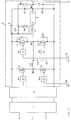
- the circuit arrangement as described in German patent application P 44 08 314.9 is composed of a radio interference filter 1, a generator 2 for generating a DC voltage and a double half-bridge 3 with an integrated pulse ignition circuit 4.
- a second half bridge with two power transistors T1, T2 and free-wheeling diodes D1, D2 connected in series is connected in parallel with the first half bridge. These two transistors T1, T2 are activated by means of control circuits A1, A2 from the same control circuit arrangement via the pulse connections P1 and P2.
- the control circuits A1 to A4 have a structure customary for such circuits and are not to be considered in more detail here.
- a current-limiting inductor L2 is connected for Simmer operation.
- a current-limiting inductor L1 for the pulse phase and the high-pressure sodium discharge lamp E is connected in series between the center tap M1 of the power transistors T1, T2 and the center tap M3 of the two electrolytic capacitors C1, C2.
- the pulse ignition circuit 4 consists of a series connection of a capacitor C3, a winding L1 'and a switching spark gap FS. This is connected on the one hand to the positive input of the double half-bridge 3 and via a resistor R1 and a switch S to the negative input of the double half-bridge 3.
- the ignition voltage is fed into the lamp by attaching the additional winding L1 'to the current-limiting inductor L1.
- the pulse ignition circuit can be controlled from the outside via an ignition connection Z between the resistor R1 and the switch S.
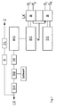
- the structure of the control circuit arrangement is shown schematically in FIG.
- the main components are the burst repetition generator WG for setting the repetition frequency of the control signal groups of the burst generator BG, the burst generator BG for generating the control signals for the pulse phase and the simmer generator SG for generating the control signals for the simmer phase.
- the burst generator BG and the simmer generator SG are connected to a logic circuit LK via two lines each.
- This logic circuit LK uses the additional signal B for the duration of the bursts from the burst generator BG to interlock the burst generator BG and the simmer generator SG and passes the signals to the pulse connections P1, P2 and the Simmer connections S1, S2 of the transistors of the power circuit arrangement further.
- the individual functional elements can be in discrete form, i.e. be designed as an oscillator or operational amplifier. However, it is also possible to implement the functional elements listed above in a microcontroller. The individual functions are then implemented using program algorithms.
Landscapes
- Circuit Arrangements For Discharge Lamps (AREA)
- Engineering & Computer Science (AREA)
- Power Engineering (AREA)
- Inverter Devices (AREA)
Applications Claiming Priority (2)
| Application Number | Priority Date | Filing Date | Title |
|---|---|---|---|
| DE4413826A DE4413826A1 (de) | 1994-04-20 | 1994-04-20 | Steuerschaltungsanordnung für eine Leistungsschaltungsanordnung zum gepulsten Betrieb einer Entladungslampe |
| DE4413826 | 1994-04-20 |
Publications (3)
| Publication Number | Publication Date |
|---|---|
| EP0679047A2 true EP0679047A2 (fr) | 1995-10-25 |
| EP0679047A3 EP0679047A3 (fr) | 1996-08-28 |
| EP0679047B1 EP0679047B1 (fr) | 2000-06-07 |
Family
ID=6516013
Family Applications (1)
| Application Number | Title | Priority Date | Filing Date |
|---|---|---|---|
| EP95104763A Expired - Lifetime EP0679047B1 (fr) | 1994-04-20 | 1995-03-30 | Circuit pour l'alimentation pulsée d'une lampe à décharge |
Country Status (5)
| Country | Link |
|---|---|
| EP (1) | EP0679047B1 (fr) |
| JP (1) | JPH07302689A (fr) |
| KR (1) | KR100334382B1 (fr) |
| CA (1) | CA2146204A1 (fr) |
| DE (2) | DE4413826A1 (fr) |
Cited By (5)
| Publication number | Priority date | Publication date | Assignee | Title |
|---|---|---|---|---|
| WO1997033453A1 (fr) * | 1996-03-06 | 1997-09-12 | Robert Bosch Gmbh | Systeme de regulation de puissance d'une lampe a decharge a haute pression a courant alternatif, notamment pour des vehicules a moteur |
| WO1999014992A1 (fr) * | 1997-09-18 | 1999-03-25 | Jbp Technologies Ltd. | Circuit permettant de synchroniser l'amorçage d'une lampe a decharge a regulateur de courant electronique |
| EP0855852A3 (fr) * | 1997-01-25 | 1999-11-03 | Robert Bosch Gmbh | Dispositif d'adaptation de la puissance delivrée à une lampe à décharge |
| WO2002098186A1 (fr) * | 2001-05-25 | 2002-12-05 | Matsushita Electric Works, Ltd. | Ballast electronique pour lampe a decharge a haute intensite |
| GB2478992A (en) * | 2010-03-26 | 2011-09-28 | Russell Jacques | Regulating controller for controlled self-oscillating converters using bipolar junction transistors |
Families Citing this family (2)
| Publication number | Priority date | Publication date | Assignee | Title |
|---|---|---|---|---|
| JP3546610B2 (ja) * | 1996-09-20 | 2004-07-28 | ウシオ電機株式会社 | 誘電体バリア放電装置 |
| RU2733920C1 (ru) * | 2019-09-16 | 2020-10-08 | АО "Элпресс" | Коммутатор мощных двуполярных импульсов тока |
Family Cites Families (3)
| Publication number | Priority date | Publication date | Assignee | Title |
|---|---|---|---|---|
| DE3636901A1 (de) * | 1986-10-30 | 1988-05-05 | Philips Patentverwaltung | Verfahren zum betrieb einer hochdruck-natriumdampfentladungslampe |
| DE3715162A1 (de) * | 1987-05-07 | 1988-11-17 | Bosch Gmbh Robert | Schaltungsanordnung zum betrieb einer gasentladungslampe an einer gleichstromquelle |
| DE4301276A1 (de) * | 1993-01-19 | 1994-07-21 | Patent Treuhand Ges Fuer Elektrische Gluehlampen Mbh | Verfahren und Stromversorgungseinheit zum stabilisierten Betrieb einer Natrium-Hochdruckentladungslampe |
-
1994
- 1994-04-20 DE DE4413826A patent/DE4413826A1/de not_active Withdrawn
-
1995
- 1995-03-30 EP EP95104763A patent/EP0679047B1/fr not_active Expired - Lifetime
- 1995-03-30 DE DE59508441T patent/DE59508441D1/de not_active Expired - Fee Related
- 1995-04-03 CA CA002146204A patent/CA2146204A1/fr not_active Abandoned
- 1995-04-20 JP JP7095626A patent/JPH07302689A/ja active Pending
- 1995-04-20 KR KR1019950009314A patent/KR100334382B1/ko not_active Expired - Fee Related
Cited By (8)
| Publication number | Priority date | Publication date | Assignee | Title |
|---|---|---|---|---|
| WO1997033453A1 (fr) * | 1996-03-06 | 1997-09-12 | Robert Bosch Gmbh | Systeme de regulation de puissance d'une lampe a decharge a haute pression a courant alternatif, notamment pour des vehicules a moteur |
| EP0855852A3 (fr) * | 1997-01-25 | 1999-11-03 | Robert Bosch Gmbh | Dispositif d'adaptation de la puissance delivrée à une lampe à décharge |
| WO1999014992A1 (fr) * | 1997-09-18 | 1999-03-25 | Jbp Technologies Ltd. | Circuit permettant de synchroniser l'amorçage d'une lampe a decharge a regulateur de courant electronique |
| WO2002098186A1 (fr) * | 2001-05-25 | 2002-12-05 | Matsushita Electric Works, Ltd. | Ballast electronique pour lampe a decharge a haute intensite |
| US7015655B2 (en) | 2001-05-25 | 2006-03-21 | Matsushita Electric Works, Ltd. | Electronic ballast for a high intensity discharge lamp |
| GB2478992A (en) * | 2010-03-26 | 2011-09-28 | Russell Jacques | Regulating controller for controlled self-oscillating converters using bipolar junction transistors |
| GB2478992B (en) * | 2010-03-26 | 2014-11-19 | Russell Jacques | Regulating controller for controlled self-oscillating converters using bipolar junction transistors |
| US9647567B2 (en) | 2010-03-26 | 2017-05-09 | Russell Jacques | Regulating controller for controlled self-oscillating converters using bipolar junction transistors |
Also Published As
| Publication number | Publication date |
|---|---|
| JPH07302689A (ja) | 1995-11-14 |
| DE4413826A1 (de) | 1995-10-26 |
| KR950035532A (ko) | 1995-12-30 |
| DE59508441D1 (de) | 2000-07-13 |
| CA2146204A1 (fr) | 1995-10-21 |
| KR100334382B1 (ko) | 2002-11-30 |
| EP0679047A3 (fr) | 1996-08-28 |
| EP0679047B1 (fr) | 2000-06-07 |
Similar Documents
| Publication | Publication Date | Title |
|---|---|---|
| DE3407067C2 (de) | Steuerschaltung für Gasentladungslampen | |
| DE3715162C2 (fr) | ||
| EP0264765B1 (fr) | Disposition de circuit pour la mise en oeuvre de lampe à incandescence halogène basse tension | |
| DE3243316C2 (de) | Elektronisches Vorschaltgerät für Gasentladungslampen zum Steuern der Leistungsaufnahme derselben | |
| DE69208218T2 (de) | Steuerungsschaltung für eine Entladungslampe | |
| DE69725974T2 (de) | Lastschaltkreis | |
| EP0763276B1 (fr) | Alimentation electrique a decoupage destinee au fonctionnement de lampes electriques | |
| DE3784956T2 (de) | Stabilisiertes netzteil, das gleichzeitig wechselstrom und gleichstrom in einem transformator erzeugt. | |
| DE3101568C2 (de) | Schaltungsanordnung zum Betrieb von Niederdruckentladungslampen mit einstellbarem Lichtstrom | |
| DE3879558T2 (de) | Resonanzwechselrichtereinrichtung und schaltung zur steuerung der resonanzwechselrichtereinrichtung. | |
| DE69902379T2 (de) | Vorschaltgerät mit helligkeitssteuerung und regelverfahren für lampen unter verwendung eines frequenzgeregelten streufeldtransformators | |
| DE3909174A1 (de) | Impuls fuer impuls stromgeregelte spannungsversorgung | |
| EP1114571A1 (fr) | Circuit pour faire fonctionner des lampes a decharge dans un gaz | |
| EP0548342A1 (fr) | Ballast d'exploitation en mode pulse de lampes luminescentes a gaz. | |
| EP0707438A2 (fr) | Ballast pour au moins une lampe à décharge | |
| DE3829388A1 (de) | Schaltungsanordnung zum betrieb einer last | |
| DE69911493T2 (de) | Beleuchtungssystem einer Entladungslampe mit Überstromschutz für die Schalter eines Wechselrichters | |
| EP0978221A1 (fr) | Circuiterie pour fonctionnement modulable d'un tube fluorescent | |
| EP0679047B1 (fr) | Circuit pour l'alimentation pulsée d'une lampe à décharge | |
| DE1489294B2 (de) | Schaltungsanordnung zum Impulsbetrieb von Gasentladungslampen | |
| EP1330945A1 (fr) | Ballast electronique avec circuit en pont integral | |
| DE4015397A1 (de) | Schaltungsanordnung zum zuenden und betreiben einer hochdruckgasentladungslampe in kraftfahrzeugen | |
| DE4238388C2 (de) | Elektronische Schaltungsanordnung zur Ansteuerung einer UV-Strahlungsquelle | |
| DE3338464A1 (de) | Hochfrequenz-helligkeitssteuerung fuer leuchtstofflampen | |
| DE10245368A1 (de) | Schweißstromquelle zum Gleich- und Wechselstromschweißen |
Legal Events
| Date | Code | Title | Description |
|---|---|---|---|
| PUAI | Public reference made under article 153(3) epc to a published international application that has entered the european phase |
Free format text: ORIGINAL CODE: 0009012 |
|
| AK | Designated contracting states |
Kind code of ref document: A2 Designated state(s): BE CH DE FR GB IT LI NL |
|
| PUAL | Search report despatched |
Free format text: ORIGINAL CODE: 0009013 |
|
| AK | Designated contracting states |
Kind code of ref document: A3 Designated state(s): BE CH DE FR GB IT LI NL |
|
| 17P | Request for examination filed |
Effective date: 19960917 |
|
| GRAG | Despatch of communication of intention to grant |
Free format text: ORIGINAL CODE: EPIDOS AGRA |
|
| 17Q | First examination report despatched |
Effective date: 19990621 |
|
| GRAG | Despatch of communication of intention to grant |
Free format text: ORIGINAL CODE: EPIDOS AGRA |
|
| GRAH | Despatch of communication of intention to grant a patent |
Free format text: ORIGINAL CODE: EPIDOS IGRA |
|
| GRAH | Despatch of communication of intention to grant a patent |
Free format text: ORIGINAL CODE: EPIDOS IGRA |
|
| GRAA | (expected) grant |
Free format text: ORIGINAL CODE: 0009210 |
|
| AK | Designated contracting states |
Kind code of ref document: B1 Designated state(s): BE CH DE FR GB IT LI NL |
|
| RIC1 | Information provided on ipc code assigned before grant |
Free format text: 7H 05B 41/288 A, 7H 05B 41/392 B |
|
| REG | Reference to a national code |
Ref country code: CH Ref legal event code: NV Representative=s name: SIEMENS SCHWEIZ AG Ref country code: CH Ref legal event code: EP |
|
| REF | Corresponds to: |
Ref document number: 59508441 Country of ref document: DE Date of ref document: 20000713 |
|
| ITF | It: translation for a ep patent filed | ||
| GBT | Gb: translation of ep patent filed (gb section 77(6)(a)/1977) |
Effective date: 20000816 |
|
| ET | Fr: translation filed | ||
| PLBE | No opposition filed within time limit |
Free format text: ORIGINAL CODE: 0009261 |
|
| STAA | Information on the status of an ep patent application or granted ep patent |
Free format text: STATUS: NO OPPOSITION FILED WITHIN TIME LIMIT |
|
| 26N | No opposition filed | ||
| REG | Reference to a national code |
Ref country code: GB Ref legal event code: IF02 |
|
| PGFP | Annual fee paid to national office [announced via postgrant information from national office to epo] |
Ref country code: NL Payment date: 20030310 Year of fee payment: 9 |
|
| PGFP | Annual fee paid to national office [announced via postgrant information from national office to epo] |
Ref country code: BE Payment date: 20030314 Year of fee payment: 9 |
|
| PGFP | Annual fee paid to national office [announced via postgrant information from national office to epo] |
Ref country code: CH Payment date: 20030612 Year of fee payment: 9 |
|
| PG25 | Lapsed in a contracting state [announced via postgrant information from national office to epo] |
Ref country code: LI Free format text: LAPSE BECAUSE OF NON-PAYMENT OF DUE FEES Effective date: 20040331 Ref country code: CH Free format text: LAPSE BECAUSE OF NON-PAYMENT OF DUE FEES Effective date: 20040331 Ref country code: BE Free format text: LAPSE BECAUSE OF NON-PAYMENT OF DUE FEES Effective date: 20040331 |
|
| BERE | Be: lapsed |
Owner name: *PATENT-TREUHAND-G.- FUR ELEKTRISCHE GLUHLAMPEN M. Effective date: 20040331 |
|
| PG25 | Lapsed in a contracting state [announced via postgrant information from national office to epo] |
Ref country code: NL Free format text: LAPSE BECAUSE OF NON-PAYMENT OF DUE FEES Effective date: 20041001 |
|
| REG | Reference to a national code |
Ref country code: CH Ref legal event code: PL |
|
| NLV4 | Nl: lapsed or anulled due to non-payment of the annual fee |
Effective date: 20041001 |
|
| PG25 | Lapsed in a contracting state [announced via postgrant information from national office to epo] |
Ref country code: IT Free format text: LAPSE BECAUSE OF NON-PAYMENT OF DUE FEES Effective date: 20050330 |
|
| PGFP | Annual fee paid to national office [announced via postgrant information from national office to epo] |
Ref country code: GB Payment date: 20060308 Year of fee payment: 12 |
|
| PGFP | Annual fee paid to national office [announced via postgrant information from national office to epo] |
Ref country code: FR Payment date: 20060324 Year of fee payment: 12 |
|
| GBPC | Gb: european patent ceased through non-payment of renewal fee |
Effective date: 20070330 |
|
| REG | Reference to a national code |
Ref country code: FR Ref legal event code: ST Effective date: 20071130 |
|
| PG25 | Lapsed in a contracting state [announced via postgrant information from national office to epo] |
Ref country code: GB Free format text: LAPSE BECAUSE OF NON-PAYMENT OF DUE FEES Effective date: 20070330 |
|
| PG25 | Lapsed in a contracting state [announced via postgrant information from national office to epo] |
Ref country code: FR Free format text: LAPSE BECAUSE OF NON-PAYMENT OF DUE FEES Effective date: 20070402 |
|
| REG | Reference to a national code |
Ref country code: DE Ref legal event code: R409 Ref document number: 59508441 Country of ref document: DE Ref country code: DE Ref legal event code: R119 Ref document number: 59508441 Country of ref document: DE |
|
| REG | Reference to a national code |
Ref country code: DE Ref legal event code: R409 Ref document number: 59508441 Country of ref document: DE |
|
| PGFP | Annual fee paid to national office [announced via postgrant information from national office to epo] |
Ref country code: DE Payment date: 20110520 Year of fee payment: 17 |
|
| REG | Reference to a national code |
Ref country code: DE Ref legal event code: R119 Ref document number: 59508441 Country of ref document: DE Effective date: 20111001 Ref country code: DE Ref legal event code: R119 Ref document number: 59508441 Country of ref document: DE Effective date: 20121002 |
|
| PG25 | Lapsed in a contracting state [announced via postgrant information from national office to epo] |
Ref country code: DE Free format text: LAPSE BECAUSE OF NON-PAYMENT OF DUE FEES Effective date: 20121002 |