EP0679047B1 - Circuit pour l'alimentation pulsée d'une lampe à décharge - Google Patents
Circuit pour l'alimentation pulsée d'une lampe à décharge Download PDFInfo
- Publication number
- EP0679047B1 EP0679047B1 EP95104763A EP95104763A EP0679047B1 EP 0679047 B1 EP0679047 B1 EP 0679047B1 EP 95104763 A EP95104763 A EP 95104763A EP 95104763 A EP95104763 A EP 95104763A EP 0679047 B1 EP0679047 B1 EP 0679047B1
- Authority
- EP
- European Patent Office
- Prior art keywords
- circuit arrangement
- control
- generator
- voltage
- simmer
- Prior art date
- Legal status (The legal status is an assumption and is not a legal conclusion. Google has not performed a legal analysis and makes no representation as to the accuracy of the status listed.)
- Expired - Lifetime
Links
Images


Classifications
-
- H—ELECTRICITY
- H05—ELECTRIC TECHNIQUES NOT OTHERWISE PROVIDED FOR
- H05B—ELECTRIC HEATING; ELECTRIC LIGHT SOURCES NOT OTHERWISE PROVIDED FOR; CIRCUIT ARRANGEMENTS FOR ELECTRIC LIGHT SOURCES, IN GENERAL
- H05B41/00—Circuit arrangements or apparatus for igniting or operating discharge lamps
- H05B41/14—Circuit arrangements
- H05B41/26—Circuit arrangements in which the lamp is fed by power derived from DC by means of a converter, e.g. by high-voltage DC
- H05B41/28—Circuit arrangements in which the lamp is fed by power derived from DC by means of a converter, e.g. by high-voltage DC using static converters
- H05B41/288—Circuit arrangements in which the lamp is fed by power derived from DC by means of a converter, e.g. by high-voltage DC using static converters with semiconductor devices and specially adapted for lamps without preheating electrodes, e.g. for high-intensity discharge lamps, high-pressure mercury or sodium lamps or low-pressure sodium lamps
- H05B41/2881—Load circuits; Control thereof
- H05B41/2882—Load circuits; Control thereof the control resulting from an action on the static converter
- H05B41/2883—Load circuits; Control thereof the control resulting from an action on the static converter the controlled element being a DC/AC converter in the final stage, e.g. by harmonic mode starting
-
- H—ELECTRICITY
- H05—ELECTRIC TECHNIQUES NOT OTHERWISE PROVIDED FOR
- H05B—ELECTRIC HEATING; ELECTRIC LIGHT SOURCES NOT OTHERWISE PROVIDED FOR; CIRCUIT ARRANGEMENTS FOR ELECTRIC LIGHT SOURCES, IN GENERAL
- H05B41/00—Circuit arrangements or apparatus for igniting or operating discharge lamps
- H05B41/14—Circuit arrangements
- H05B41/30—Circuit arrangements in which the lamp is fed by pulses, e.g. flash lamp
-
- Y—GENERAL TAGGING OF NEW TECHNOLOGICAL DEVELOPMENTS; GENERAL TAGGING OF CROSS-SECTIONAL TECHNOLOGIES SPANNING OVER SEVERAL SECTIONS OF THE IPC; TECHNICAL SUBJECTS COVERED BY FORMER USPC CROSS-REFERENCE ART COLLECTIONS [XRACs] AND DIGESTS
- Y02—TECHNOLOGIES OR APPLICATIONS FOR MITIGATION OR ADAPTATION AGAINST CLIMATE CHANGE
- Y02B—CLIMATE CHANGE MITIGATION TECHNOLOGIES RELATED TO BUILDINGS, e.g. HOUSING, HOUSE APPLIANCES OR RELATED END-USER APPLICATIONS
- Y02B20/00—Energy efficient lighting technologies, e.g. halogen lamps or gas discharge lamps
Definitions
- the invention relates to a control circuit arrangement for a power circuit arrangement for pulsed operation of a discharge lamp, in particular High pressure sodium discharge lamp according to the Preamble of claim 1.
- the pulsed operation of discharge lamps in particular High pressure sodium discharge lamps particularly high demands on power electronics the circuit arrangement.
- high pressure sodium discharge lamps an optimal setting of the lighting Data such as burning voltage, luminous efficacy, color temperature and color rendering index, by the scheme the vapor pressure.
- the Vapor pressure can affect the impedance of the plasma Serve lamp, it being used for stabilized operation the lamp only needs the output power regulate the power supply so that the Impedance of the lamp takes the value found.
- the impedance of the lamp can basically be determined by Formation of the quotient from the lamp voltage and the lamp current can be obtained, in pulse mode both the respective value in the pulse phase can also be used in the holding phase.
- a power supply with opposite Mains voltage fluctuations of stabilized open circuit voltage and given output impedance is sufficient it even, just the current or the voltage to regulate the lamp to the specified target value, which is the optimum value of the vapor pressure and thus the the color rendering properties and the luminous efficacy and corresponds to the burning voltage.
- pulse operation of the lamp by a power supply with against mains voltage fluctuations stabilized open circuit voltage and predetermined Output impedance is one of the control variables Sizes pulse voltage, pulse current, holding voltage or holding current. The readjustment of the lamp power can then either by changing the Width and distance of the power pulses and / or the holding power can be realized.
- European patent application EP-A-0 671 868 which is considered prior art under Article 54 (3) EPC, a power circuit arrangement for pulsed operation of discharge lamps, in particular High pressure sodium discharge lamps described, which ensures optimal operation of these lamps.
- This power circuit arrangement has two half bridges connected in parallel, the can be controlled separately, each half-bridge assigned its own current-limiting inductance is. This is an independent regulation of the Currents with freely selectable depending on the inductance Operating frequencies during the holding phase (Simmer current operation) and during the pulse phase (pulse current operation) possible so that the pulse mode completely free to meet the needs of those operating Discharge lamp can be adjusted.
- the object of the invention is now a control circuit arrangement for the power circuit arrangement listed above to create that with few Components gets along and can be realized inexpensively is. With the control circuitry should no restriction in the realization of the Operating currents and frequencies through the power circuit arrangement be connected.
- Control of the power circuitry is based on that in the German patent application DE 4 301 276 A1 identified knowledge that the Lamp supplied power consumption and thus also the properties of the Discharge lamp, e.g. the color rendering, proportional to the lamp voltage when stamped Depend on lamp current.
- the control circuitry consists of a burst generator for generation the control signals for the pulse phase, one Simmer generator for generating the control signals for the simmer phase and a burst repeat generator to set the time interval between the pulse phases.
- the means of these assemblies generated signals are through a logic circuit and corresponding control circuits to the pulse connections or Simmer connections of the transistors given the power circuit arrangement.
- the Logic circuit ensures that during the Simmerphase that to the transistors for pulsed operation given signal zero and during the pulse phase that to the transistors for Simmer operation given signal is zero.
- the simmer phase is via the voltage tap on the center tap between the two transistors for the pulse phase the power circuit arrangement one of the lamp voltage proportional voltage tapped and too a defined point in time between the pulse bursts stored in a sample and hold link.
- this voltage is released a setpoint voltage at which an optimal Operation of the high pressure sodium discharge lamp given is compared. If the actual value voltage deviates of the setpoint voltage causes an integral controller a frequency change on the burst repeat generator and thus causes a change in the lamp fed power. This change in performance has a change in lamp voltage result in an optimal working point is regulated.
- This circuit structure additionally enables the shifting of the Color temperature of the high pressure sodium discharge lamp between 2500 and 3000 K without losing the color rendering index is changed.
- the color temperature can therefore as in the German patent application DE 4 301 256 A1 generally represented by the Change the number of control signals for the Pulse phase and the change in the length of these control signals and / or the length of the control signals for the simmer phase and adjustment of the actual value voltage to a correspondingly changed setpoint voltage can be varied.
- the burst generator and the simmer generator exist advantageously from a controlled oscillator.
- the controlled oscillator of the burst generator advantageously an oscillation counter connected downstream, where both are linked by a logic element.
- the burst repetition generator advantageously consists of a variable frequency oscillator.
- the Sample and hold link is advantageous from one controllable switch with a downstream Memory element built up during the integral controller from an operational amplifier or a digital one Positioning algorithm exists.
- the control shutdown arrangement can be advantageous additionally include a comparator, on the one hand via monitoring logic with the control connection the pulse ignition circuit in the power circuit arrangement and on the other hand with the entrance of the sample and hold link is linked. In this way, ignition monitoring of the sodium high-pressure discharge lamp created.
- the on the The voltage applied is measured by the comparator compared to a reference voltage. Exceeds this is the reference voltage, so in the power circuit arrangement by closing one Switch activates the pulse ignition circuit.
- control shutdown arrangement enables in addition an independent adjustability of the Color temperature and the color rendering index too a power control of the high pressure sodium discharge lamp with that in the German patent application Power circuit arrangement listed in DE 4 301 276 A1, without the color temperature essential being affected. This allows e.g. the Performance of high pressure sodium discharge lamps for Outdoor lighting systems on during the night to switch half power down.
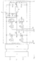
- FIG. 2 is the structure of the power circuit arrangement for pulsed operation of a high pressure sodium discharge lamp E shown.
- the circuit arrangement as used in the European Patent application EP-A-0 671 868 consists of a radio interference filter 1, a Generator 2 for generating a DC voltage and a double half bridge 3 with an integrated Pulse ignition circuit 4 together.
- the radio interference filter 1 has a known one conventional structure and should not be described here to be viewed as.
- the DC voltage generator 2 includes a rectifier bridge and one Boost converter of known design and produced a stabilized DC voltage at its output.
- the double half bridge 3 includes a first half bridge with two MOS-FET transistors connected in series T3, T4 parallel to the output of the generator 2 to generate the simmer phase.
- the control of the two transistors T3, T4 takes place by means of Control circuits A3 and A4 from that described below Control circuitry over the Simmer connections S1 and S2.
- a second is parallel to the first half-bridge Half bridge with two power transistors connected in series T1, T2 and free-wheeling diodes D1, D2 switched.
- the control of these two transistors T1, T2 takes place by means of control circuits A1, A2 from the same control circuit arrangement the pulse connections P1 and P2.
- the control circuits A1 to A4 have one for such circuits usual structure and are not intended here to be viewed as.
- the pulse ignition circuit 4 consists of a series connection a capacitor C3, a winding L1 'and a switching spark gap FS. This is on the one hand with the positive input of the double half-bridge 3 and via a resistor R1 and one Switch S with the negative input of the double half bridge 3 connected.
- the supply of the ignition voltage into the lamp by attaching the additional winding L1 'on the current limiting Inductance L1.
- Via an ignition connection Z between the resistor R1 and the switch S can Pulse ignition can be controlled from the outside.
- Main ingredients are the burst repetition generator WG for adjustment the repetition frequency of the control signal groups Burstgenerators BG, the burst generator BG for Generation of the control signals for the pulse phase and the simmer generator SG for generating the control signals for the simmer phase.
- the burst generator BG and the Simmer generator SG connected to a logic circuit LK.
- This Logic circuit LK takes with the help of the additional Signal B for the duration of the bursts from the Burst generator BG interlock from burst generator BG and Simmergenerator SG and passes the signals to the pulse connections P1, P2 or the simmer connections S1, S2 of the transistors the power circuit arrangement further.
- the burst repetition generator WG is for control the repetition frequency via an integral controller IR, a subtractor SB, which is a setpoint comparison and a sample and hold link SH with the Voltage tap LS of the power circuit arrangement connected. It is also used to control the Pulse ignition circuit of the ignition control connection Z via a monitoring logic ZL and a comparator K with the input of the sample and hold element SH connected.
- the individual functional elements can be in discrete Shape, i.e. as an oscillator or operational amplifier be executed. But it is also possible to do the above listed functional elements in a microcontroller to implement. The individual functions are then implemented using program algorithms.
- Fig. 3 is purely schematic of the timing of the control signals given to the pulse connections P1 and P2 of the transistors for the pulse phase and the Simmer connections S1 and S2 of the transistors for the Simmer phase and the pulse-shaped current I L generated by this control by the power circuit arrangement, such as it is made available to the discharge lamp.
Landscapes
- Circuit Arrangements For Discharge Lamps (AREA)
- Engineering & Computer Science (AREA)
- Power Engineering (AREA)
- Inverter Devices (AREA)
Claims (9)
- Circuit de commande pour un circuit de puissance servant au fonctionnement pulsé d'une lampe à décharge, notamment une lampe à décharge au sodium à haute pression, dans lequel le circuit de puissance comprend :caractérisé en ce que le circuit de commande comprend :un générateur (2) pour produire une tension continue positive,un demi-pont double (3), consistant en deux demi-ponts montés en parallèle et comportant des transistors (T1, T2 ; T3, T4) en tant que moyens de commutation pour produire une phase d'impulsions ou bien une phase de maintien, et une borne de commande (P1, P2; S1, S2) pour chaque transistor (T1, T2 ; T3, T4),un circuit d'amorçage d'impulsion (4), intégré dans le demi-pont double (3) et comportant une borne de commande d'amorçage (Z);ainsi qu'une prise de tension (LS), réalisée par l'intermédiaire d'un condensateur (C4) et d'une résistance (R2) au niveau de la prise médiane (M1) entre les deux transistors (T1, T2), pour la phase d'impulsion ;un générateur de salves (BG) pour produire un nombre défini de signaux rectangulaires de commande d'une longueur déterminée pour la phase d'impulsions et pour la fourniture complémentaire de ce groupe de signaux de commande, par l'intermédiaire de deux lignes séparées, à un circuit logique (LK) en même temps qu'un signal B, qui correspond à la durée du groupe de signaux de commande,un générateur de maintien (SG) pour la production continue de signaux rectangulaires de commande d'une longueur déterminée pour la phase de maintien et pour la fourniture complémentaire de ces signaux de commande, par l'intermédiaire de deux lignes séparées, à un circuit logique (LK),un générateur de répétition de salves (WG) pour le réglage d'une fréquence de récurrence prédéterminée pour les groupes de signaux de commande du générateur de salves (BG),un circuit logique (LK) pour la retransmission des signaux de commande pour la phase d'impulsions, pendant la phase d'impulsions correspondante, aux bornes de commande P1 et P2, et pour la retransmission des signaux de commande pour la phase de maintien, entre les temps de la phase d'impulsions, aux bornes de commande S1, S2,un montage d'échantillonnage (SH), qui prélève et qui conserve, par l'intermédiaire de la prise de tension (LS) au niveau de la prise médiane (M1) entre les deux transistors (T1, T2), pour la phase d'impulsions, une tension effective instantanée à un positionnement temporel défini entre les groupes de signaux de commande du générateur de salves (BG),un soustracteur (SB), qui compare cette tension prélevée à une tension de consigne, etun régulateur à action intégrale (IR) qui procède, lors d'un écart de la tension effective par rapport à la tension de consigne, à une modification de la fréquence au niveau du générateur de répétition de salves (WG).
- Circuit de commande selon la revendication 1, caractérisé en ce que le générateur de salves (BG) consiste en un oscillateur commandé, à la suite duquel est monté un compteur d'oscillations, l'oscillateur étant associé au compteur d'oscillations par un élément logique.
- Circuit de commande selon la revendication 1, caractérisé en ce que le générateur de maintien (SG) consiste en un oscillateur commandé.
- Circuit de commande selon la revendication 1, caractérisé en ce que le générateur de répétition de salves (WG) consiste en un oscillateur à fréquence variable.
- Circuit de commande selon la revendication 1, caractérisé en ce que le circuit logique (LK) consiste en une logique.
- Circuit de commande selon la revendication 1, caractérisé en ce que le montage d'échantillonnage (SH) consiste en un commutateur pouvant être commandé et à la suite duquel est monté un élément de conservation.
- Circuit de commande selon la revendication 1, caractérisé en ce que le régulateur à action intégrale (IR) consiste en un amplificateur opérationnel ou en un algorithme numérique de position .
- Circuit de commande selon la revendication 1, caractérisé en ce que le circuit comprend en outre un comparateur (K) qui est relié, d'une part, par l'intermédiaire d'une logique de surveillance (ZL), à la borne de commande d'amorçage (Z) du circuit de puissance et, d'autre part, au soustracteur (SB).
- Circuit de commande selon la revendication 1, caractérisé en ce que les éléments fonctionnels discrets sont réalisés par un microrégisseur approprié ayant des algorithmes de programme correspondants.
Applications Claiming Priority (2)
| Application Number | Priority Date | Filing Date | Title |
|---|---|---|---|
| DE4413826 | 1994-04-20 | ||
| DE4413826A DE4413826A1 (de) | 1994-04-20 | 1994-04-20 | Steuerschaltungsanordnung für eine Leistungsschaltungsanordnung zum gepulsten Betrieb einer Entladungslampe |
Publications (3)
| Publication Number | Publication Date |
|---|---|
| EP0679047A2 EP0679047A2 (fr) | 1995-10-25 |
| EP0679047A3 EP0679047A3 (fr) | 1996-08-28 |
| EP0679047B1 true EP0679047B1 (fr) | 2000-06-07 |
Family
ID=6516013
Family Applications (1)
| Application Number | Title | Priority Date | Filing Date |
|---|---|---|---|
| EP95104763A Expired - Lifetime EP0679047B1 (fr) | 1994-04-20 | 1995-03-30 | Circuit pour l'alimentation pulsée d'une lampe à décharge |
Country Status (5)
| Country | Link |
|---|---|
| EP (1) | EP0679047B1 (fr) |
| JP (1) | JPH07302689A (fr) |
| KR (1) | KR100334382B1 (fr) |
| CA (1) | CA2146204A1 (fr) |
| DE (2) | DE4413826A1 (fr) |
Families Citing this family (7)
| Publication number | Priority date | Publication date | Assignee | Title |
|---|---|---|---|---|
| DE19608655A1 (de) * | 1996-03-06 | 1997-09-11 | Bosch Gmbh Robert | Leistungssteuerung einer mit Wechselstrom betriebenen Hochdruckgasentladungslampe, insbesondere für Kraftfahrzeuge |
| JP3546610B2 (ja) * | 1996-09-20 | 2004-07-28 | ウシオ電機株式会社 | 誘電体バリア放電装置 |
| DE19702653A1 (de) * | 1997-01-25 | 1998-07-30 | Bosch Gmbh Robert | Anordnung zur Leistungsanpassung einer Gasentladungslampe |
| IL121801A (en) * | 1997-09-18 | 2000-08-13 | Jbp Technologies Ltd | Circuit for synchronizing the ignition of electronic ballast discharge lamps |
| US7015655B2 (en) | 2001-05-25 | 2006-03-21 | Matsushita Electric Works, Ltd. | Electronic ballast for a high intensity discharge lamp |
| GB2478992B (en) | 2010-03-26 | 2014-11-19 | Russell Jacques | Regulating controller for controlled self-oscillating converters using bipolar junction transistors |
| RU2733920C1 (ru) * | 2019-09-16 | 2020-10-08 | АО "Элпресс" | Коммутатор мощных двуполярных импульсов тока |
Family Cites Families (3)
| Publication number | Priority date | Publication date | Assignee | Title |
|---|---|---|---|---|
| DE3636901A1 (de) * | 1986-10-30 | 1988-05-05 | Philips Patentverwaltung | Verfahren zum betrieb einer hochdruck-natriumdampfentladungslampe |
| DE3715162A1 (de) * | 1987-05-07 | 1988-11-17 | Bosch Gmbh Robert | Schaltungsanordnung zum betrieb einer gasentladungslampe an einer gleichstromquelle |
| DE4301276A1 (de) * | 1993-01-19 | 1994-07-21 | Patent Treuhand Ges Fuer Elektrische Gluehlampen Mbh | Verfahren und Stromversorgungseinheit zum stabilisierten Betrieb einer Natrium-Hochdruckentladungslampe |
-
1994
- 1994-04-20 DE DE4413826A patent/DE4413826A1/de not_active Withdrawn
-
1995
- 1995-03-30 EP EP95104763A patent/EP0679047B1/fr not_active Expired - Lifetime
- 1995-03-30 DE DE59508441T patent/DE59508441D1/de not_active Expired - Fee Related
- 1995-04-03 CA CA002146204A patent/CA2146204A1/fr not_active Abandoned
- 1995-04-20 KR KR1019950009314A patent/KR100334382B1/ko not_active Expired - Fee Related
- 1995-04-20 JP JP7095626A patent/JPH07302689A/ja active Pending
Also Published As
| Publication number | Publication date |
|---|---|
| JPH07302689A (ja) | 1995-11-14 |
| DE59508441D1 (de) | 2000-07-13 |
| EP0679047A3 (fr) | 1996-08-28 |
| CA2146204A1 (fr) | 1995-10-21 |
| EP0679047A2 (fr) | 1995-10-25 |
| KR100334382B1 (ko) | 2002-11-30 |
| KR950035532A (ko) | 1995-12-30 |
| DE4413826A1 (de) | 1995-10-26 |
Similar Documents
| Publication | Publication Date | Title |
|---|---|---|
| DE3407067C2 (de) | Steuerschaltung für Gasentladungslampen | |
| DE68918034T2 (de) | Leistungssteuerschaltung für Gasentladungslampen und Verfahren für den Betrieb. | |
| DE69725974T2 (de) | Lastschaltkreis | |
| DE3715162C2 (fr) | ||
| DE3420469C2 (de) | Schaltungsanordnung zur Steuerung eines Resonanz-Wechselrichters | |
| DE69019862T2 (de) | Anordnung zur Versorgung einer Entladungslampe. | |
| EP0264765B1 (fr) | Disposition de circuit pour la mise en oeuvre de lampe à incandescence halogène basse tension | |
| DE69208218T2 (de) | Steuerungsschaltung für eine Entladungslampe | |
| DE4332059B4 (de) | Vorschaltgerät zur Helligkeitssteuerung von Entladungslampen | |
| DE60225425T2 (de) | Elektronisch dimmbare ballastschaltung für eine hochintensitätsentladungslampe | |
| DE69902379T2 (de) | Vorschaltgerät mit helligkeitssteuerung und regelverfahren für lampen unter verwendung eines frequenzgeregelten streufeldtransformators | |
| DE3101568C2 (de) | Schaltungsanordnung zum Betrieb von Niederdruckentladungslampen mit einstellbarem Lichtstrom | |
| EP0548342A1 (fr) | Ballast d'exploitation en mode pulse de lampes luminescentes a gaz. | |
| EP0707438A2 (fr) | Ballast pour au moins une lampe à décharge | |
| DE2705984A1 (de) | Wechselrichter mit konstanter ausgangsleistung | |
| DE69616479T2 (de) | Schaltungsanordnung | |
| DE2036627B2 (de) | Speiseschaltung für Gasentladungslampen | |
| DE3829388A1 (de) | Schaltungsanordnung zum betrieb einer last | |
| DE69911493T2 (de) | Beleuchtungssystem einer Entladungslampe mit Überstromschutz für die Schalter eines Wechselrichters | |
| EP0679047B1 (fr) | Circuit pour l'alimentation pulsée d'une lampe à décharge | |
| WO1998048597A1 (fr) | Circuiterie pour fonctionnement modulable d'un tube fluorescent | |
| DE4015397A1 (de) | Schaltungsanordnung zum zuenden und betreiben einer hochdruckgasentladungslampe in kraftfahrzeugen | |
| DE4441140A1 (de) | Dimmschaltung für Leuchtstofflampen | |
| DE10051139A1 (de) | Elektronisches Vorschaltgerät mit Vollbrückenschaltung | |
| DE3400580C2 (fr) |
Legal Events
| Date | Code | Title | Description |
|---|---|---|---|
| PUAI | Public reference made under article 153(3) epc to a published international application that has entered the european phase |
Free format text: ORIGINAL CODE: 0009012 |
|
| AK | Designated contracting states |
Kind code of ref document: A2 Designated state(s): BE CH DE FR GB IT LI NL |
|
| PUAL | Search report despatched |
Free format text: ORIGINAL CODE: 0009013 |
|
| AK | Designated contracting states |
Kind code of ref document: A3 Designated state(s): BE CH DE FR GB IT LI NL |
|
| 17P | Request for examination filed |
Effective date: 19960917 |
|
| GRAG | Despatch of communication of intention to grant |
Free format text: ORIGINAL CODE: EPIDOS AGRA |
|
| 17Q | First examination report despatched |
Effective date: 19990621 |
|
| GRAG | Despatch of communication of intention to grant |
Free format text: ORIGINAL CODE: EPIDOS AGRA |
|
| GRAH | Despatch of communication of intention to grant a patent |
Free format text: ORIGINAL CODE: EPIDOS IGRA |
|
| GRAH | Despatch of communication of intention to grant a patent |
Free format text: ORIGINAL CODE: EPIDOS IGRA |
|
| GRAA | (expected) grant |
Free format text: ORIGINAL CODE: 0009210 |
|
| AK | Designated contracting states |
Kind code of ref document: B1 Designated state(s): BE CH DE FR GB IT LI NL |
|
| RIC1 | Information provided on ipc code assigned before grant |
Free format text: 7H 05B 41/288 A, 7H 05B 41/392 B |
|
| REG | Reference to a national code |
Ref country code: CH Ref legal event code: NV Representative=s name: SIEMENS SCHWEIZ AG Ref country code: CH Ref legal event code: EP |
|
| REF | Corresponds to: |
Ref document number: 59508441 Country of ref document: DE Date of ref document: 20000713 |
|
| ITF | It: translation for a ep patent filed | ||
| GBT | Gb: translation of ep patent filed (gb section 77(6)(a)/1977) |
Effective date: 20000816 |
|
| ET | Fr: translation filed | ||
| PLBE | No opposition filed within time limit |
Free format text: ORIGINAL CODE: 0009261 |
|
| STAA | Information on the status of an ep patent application or granted ep patent |
Free format text: STATUS: NO OPPOSITION FILED WITHIN TIME LIMIT |
|
| 26N | No opposition filed | ||
| REG | Reference to a national code |
Ref country code: GB Ref legal event code: IF02 |
|
| PGFP | Annual fee paid to national office [announced via postgrant information from national office to epo] |
Ref country code: NL Payment date: 20030310 Year of fee payment: 9 |
|
| PGFP | Annual fee paid to national office [announced via postgrant information from national office to epo] |
Ref country code: BE Payment date: 20030314 Year of fee payment: 9 |
|
| PGFP | Annual fee paid to national office [announced via postgrant information from national office to epo] |
Ref country code: CH Payment date: 20030612 Year of fee payment: 9 |
|
| PG25 | Lapsed in a contracting state [announced via postgrant information from national office to epo] |
Ref country code: LI Free format text: LAPSE BECAUSE OF NON-PAYMENT OF DUE FEES Effective date: 20040331 Ref country code: CH Free format text: LAPSE BECAUSE OF NON-PAYMENT OF DUE FEES Effective date: 20040331 Ref country code: BE Free format text: LAPSE BECAUSE OF NON-PAYMENT OF DUE FEES Effective date: 20040331 |
|
| BERE | Be: lapsed |
Owner name: *PATENT-TREUHAND-G.- FUR ELEKTRISCHE GLUHLAMPEN M. Effective date: 20040331 |
|
| PG25 | Lapsed in a contracting state [announced via postgrant information from national office to epo] |
Ref country code: NL Free format text: LAPSE BECAUSE OF NON-PAYMENT OF DUE FEES Effective date: 20041001 |
|
| REG | Reference to a national code |
Ref country code: CH Ref legal event code: PL |
|
| NLV4 | Nl: lapsed or anulled due to non-payment of the annual fee |
Effective date: 20041001 |
|
| PG25 | Lapsed in a contracting state [announced via postgrant information from national office to epo] |
Ref country code: IT Free format text: LAPSE BECAUSE OF NON-PAYMENT OF DUE FEES Effective date: 20050330 |
|
| PGFP | Annual fee paid to national office [announced via postgrant information from national office to epo] |
Ref country code: GB Payment date: 20060308 Year of fee payment: 12 |
|
| PGFP | Annual fee paid to national office [announced via postgrant information from national office to epo] |
Ref country code: FR Payment date: 20060324 Year of fee payment: 12 |
|
| GBPC | Gb: european patent ceased through non-payment of renewal fee |
Effective date: 20070330 |
|
| REG | Reference to a national code |
Ref country code: FR Ref legal event code: ST Effective date: 20071130 |
|
| PG25 | Lapsed in a contracting state [announced via postgrant information from national office to epo] |
Ref country code: GB Free format text: LAPSE BECAUSE OF NON-PAYMENT OF DUE FEES Effective date: 20070330 |
|
| PG25 | Lapsed in a contracting state [announced via postgrant information from national office to epo] |
Ref country code: FR Free format text: LAPSE BECAUSE OF NON-PAYMENT OF DUE FEES Effective date: 20070402 |
|
| REG | Reference to a national code |
Ref country code: DE Ref legal event code: R409 Ref document number: 59508441 Country of ref document: DE Ref country code: DE Ref legal event code: R119 Ref document number: 59508441 Country of ref document: DE |
|
| REG | Reference to a national code |
Ref country code: DE Ref legal event code: R409 Ref document number: 59508441 Country of ref document: DE |
|
| PGFP | Annual fee paid to national office [announced via postgrant information from national office to epo] |
Ref country code: DE Payment date: 20110520 Year of fee payment: 17 |
|
| REG | Reference to a national code |
Ref country code: DE Ref legal event code: R119 Ref document number: 59508441 Country of ref document: DE Effective date: 20111001 Ref country code: DE Ref legal event code: R119 Ref document number: 59508441 Country of ref document: DE Effective date: 20121002 |
|
| PG25 | Lapsed in a contracting state [announced via postgrant information from national office to epo] |
Ref country code: DE Free format text: LAPSE BECAUSE OF NON-PAYMENT OF DUE FEES Effective date: 20121002 |