EP0679513A2 - Dispositif de guidage d'un support d'impression - Google Patents
Dispositif de guidage d'un support d'impression Download PDFInfo
- Publication number
- EP0679513A2 EP0679513A2 EP95104640A EP95104640A EP0679513A2 EP 0679513 A2 EP0679513 A2 EP 0679513A2 EP 95104640 A EP95104640 A EP 95104640A EP 95104640 A EP95104640 A EP 95104640A EP 0679513 A2 EP0679513 A2 EP 0679513A2
- Authority
- EP
- European Patent Office
- Prior art keywords
- guide elements
- guide
- print carrier
- pair
- plate
- Prior art date
- Legal status (The legal status is an assumption and is not a legal conclusion. Google has not performed a legal analysis and makes no representation as to the accuracy of the status listed.)
- Granted
Links
- 238000011161 development Methods 0.000 description 3
- 230000018109 developmental process Effects 0.000 description 3
- 238000003780 insertion Methods 0.000 description 2
- 230000037431 insertion Effects 0.000 description 2
- 238000000034 method Methods 0.000 description 2
- 239000000853 adhesive Substances 0.000 description 1
- 230000001070 adhesive effect Effects 0.000 description 1
- 239000000969 carrier Substances 0.000 description 1
- 238000004140 cleaning Methods 0.000 description 1
- 238000010276 construction Methods 0.000 description 1
- 230000008878 coupling Effects 0.000 description 1
- 238000010168 coupling process Methods 0.000 description 1
- 238000005859 coupling reaction Methods 0.000 description 1
- 210000003746 feather Anatomy 0.000 description 1
- 125000006850 spacer group Chemical group 0.000 description 1
Images





Classifications
-
- B—PERFORMING OPERATIONS; TRANSPORTING
- B41—PRINTING; LINING MACHINES; TYPEWRITERS; STAMPS
- B41F—PRINTING MACHINES OR PRESSES
- B41F27/00—Devices for attaching printing elements or formes to supports
- B41F27/12—Devices for attaching printing elements or formes to supports for attaching flexible printing formes
- B41F27/1206—Feeding to or removing from the forme cylinder
Definitions
- the invention relates to a device for guiding a printing medium when feeding and removing the printing medium to and from a plate cylinder of a printing press.
- the invention has for its object to provide a device that allows a reliable supply and discharge of a printing medium to or from a plate cylinder.
- the device according to the invention achieves problem-free guiding of the printing medium when changing plates.
- the two guide elements ensure that that the surface of the print carrier does not come into contact with machine parts; this effectively prevents damage to the sensitive printing surface.
- the device is also designed so that one of the two guide elements only comes into contact with the surface of the not yet printed, color-free printing medium (printing plate, printing film), while the other only comes into contact with the surface of the already printed, color-bearing printing medium comes into contact, soiling of an as yet unprinted print carrier, in particular when clamping onto the plate cylinder, is excluded from the outset.
- the two guide elements are a pair of rollers.
- Inexpensive - or required in certain embodiments - is also the design to use roller-shaped segments or runners instead of continuous rollers.
- Such an embodiment is less expensive, but can also prove to be expedient or must be turned out to be necessary to avoid a collision with the grippers of the terminal strips of the clamping and tensioning devices.
- the guide elements are arranged eccentrically on a traverse. Depending on the pivoted position, this offset means that only the desired guide element comes into contact with the surface of the print carrier.
- An inexpensive variant of the device according to the invention provides the following adjusting mechanism for pivoting the crossbar.
- Two friction wheels are rotatably mounted in the end areas of the traverse.
- a freewheel is assigned to each of these friction wheels, with a freewheel opposite direction of entrainment of the other.
- the traverse itself is spring-mounted in a pivoted lever. Via a curve control, the friction wheels are pressed against the bearer rings of the printing cylinder while a pressure carrier is being fed in or out.
- the crosshead with the two guide elements is automatically brought into the desired positions in accordance with the driving directions of the freewheels which are coordinated with the direction of rotation of the plate cylinder when the pressure carrier is fed in and out.
- a lever is fastened to the crossmember and can be actuated via an actuating element, for example an actuating cylinder with two working positions, a motor or a magnet .
- a further crossmember is provided between the pivotable levers, on which at least one guide element is fixed.
- the guide element is rigidly attached to the feed table.
- the guide element ensures safe removal of the plate to the feed table.
- the guide elements are advantageously arranged in a gap between the grippers of the adhesive strips.
- the configuration of attaching the device for feeding and removing the printing medium to a pivotably mounted protection of a printing unit proves to be advantageous.
- the device can then be removed at the same time as the protection, which is inevitably necessary if work is to be carried out on the rollers and cylinders of the printing unit.
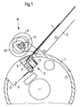
- Figures 1 to 5 show an advantageous embodiment of the device according to the invention for feeding and removing pressure carriers in the two working positions (position A, position B).
- the embodiments with which the two different positions (A, B) can be controlled are described later.
- Fig. 1 shows the position of the pair of rollers 8 at a time when the print carrier 1 (printing plate or printing film) guided over the feed table 2 is placed between the clamping surfaces 4a, 5a of the two clamping strips 4, 5 of the leading edge clamping device 3.
- the front edge of the pressure plate 1 is clamped in that one of the two clamping surfaces 4a, 5a is moved perpendicular to the other clamping surface 4a, 5a.
- the clamping device 3 is arranged in the cylinder channel 6 of the plate cylinder 7 of a printing machine, which is not shown separately.
- this position A defined as the starting position the pair of rollers 8, consisting of the two guide rollers 9, 10, is set down from the surface of the plate cylinder 7.
- the two idlers 9, 10 are mounted eccentrically on a swiveling crossbar 11.
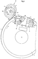
- Figures 2 and 3 show the position of the pair of rollers 8 during the mounting of the printing plate 1 on the plate cylinder 7 again (position B).
- the pair of rollers swivels in position B to a defined distance from the plate cylinder by a pivoting movement of the crossmember 11.
- the guide roller 9 holds the plate down while the plate cylinder 7 rotates in the direction of the arrow about its central axis.
- the pair of rollers 8 remains in this position until the rear edge of the pressure plate 1 is fixed between the clamping surfaces 15a, 16a of the clamping strips 15, 16 of the trailing edge clamping and tensioning device 14 after one rotation of the plate cylinder.
- Devices for clamping and tensioning printing plates 1 have already become well known. To name possible embodiments for such devices, reference is made to DE 41 28 994 A1 or DE 41 29 831 A1.
- a guide element 18 is provided, which is part of the feed table 2.
- the pair of rollers 8 swings into the second position (position A). As soon as the clamping and tensioning device 14 releases the plate trailing edge, it springs out of the holder due to the internal stress and comes into contact with the surface of the guide roller 10. During the rotation of the plate cylinder 7 and thus the unwinding of the pressure plate 1, it becomes on the guide roller 10 passed and pushed onto the feed table 2.
- the guide elements 18 advantageously support the 'ejection' of the pressure plate 1.
- FIGS. 4 and 5 This state of affairs is illustrated in FIGS. 4 and 5.
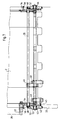
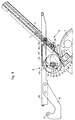
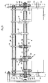
- Fig. 6 shows a side view of the pair of rollers with a first embodiment of an on and off mechanism; in Fig. 7 the corresponding device is shown in plan view.
- the guide rollers 9, 10 are rigidly mounted on a rotatably mounted crossmember 11 - in the case shown it is a square.
- the two guide rollers 9, 10 are composed of eccentrically mounted roller-shaped segments 49 which are arranged in such a way that the two positions (position A, position B) of the guide rollers 9, 10 can be realized by rotating the crossbar 11 by a certain angle.
- the distance between the roller-shaped segments 49 is dimensioned such that a collision with the clamping strips 4.15 of the clamping and tensioning devices 3.14 on the plate cylinder 7 is excluded.
- the end regions 52 of the crossmember 11 are rotatably supported by bushings 53 in bearing levers 54 arranged on both sides.
- the end regions 52 of the crossmember 11 carry friction wheels 42.
- Each friction wheel 42 is assigned a freewheel 43, 44 with the opposite driving direction on the drive and operator side.
- the shaft 55 is rotatably supported in the bearing levers 54 and the fastening parts 54 rigidly connected to the printing unit protection 29.
- a bolt 51, which interacts with a curve 28, is attached to the fastening part 53 on the drive side.
- the bearing levers 54 carrying the pair of rollers 8 are rotated about the central axis of the shaft 55.
- work is done against the force of the tension spring 50.
- the pivoting movement of the bearing levers 54 causes the friction wheels 42, each of which has a rubber ring 48 on its circumference, to be applied to the bearer rings 33 of the plate cylinder 7 pressed.
- the driving direction of the freewheels 43, 44 is designed in such a way that the guide roller 9 is in the case of the plate feed and the guide roller 10 is in the vicinity of the pressure plate 1 in the case of the plate ejection.
- 49 limiting pins 45 are attached to the two outer roller-shaped segments, which engage in the two required angular positions strike the edges of the appropriately designed fastening parts 56.
- the attachment points are marked with 'x' in FIG. 6.
- the guide rollers 9, 10 which in turn consist of individual roller-shaped segments 49 in the case shown, are rigidly attached to a rotatably mounted crossmember 11, in the case shown on a square. Since the roller-shaped segments 49 of each of the two guide rollers 9, 10 are arranged eccentrically, the two desired positions can be set by rotating the crossmember 11.
- the crossmember 11 carries bearings 20 on both sides, which are each mounted in an elongated hole 21 of the fastening parts 27 on springs 22. A force is exerted on the spring-mounted crossmember 11, with the guide rollers 9, 10, controlled via a curve 28, in order to adjust the two positions of the roller pair 8.
- 11 friction wheels 42 are rotatably mounted on the cross member.
- the friction wheels 42 each have a protruding rubber ring 48 on their circumference.
- a further cross member 25 couples the two levers 24 rigidly to one another. Is on the two levers 24 and thus on the crossbar 11th and the guide rollers 9, 10 exert a force by means of the cam control, the friction wheels 42 are pressed onto the bearer rings 33 of the plate cylinder 7.
- the friction wheels 42 each have a freewheel 43, 44, the freewheel 44 on the operator side having a different driving direction than the freewheel 43 on the drive side.
- the direction of travel of the freewheels 43, 44 is selected such that the crossmember 11 with the guide rollers 9, 10 is pivoted into position B in the case of plate insertion and into position A in the case of plate ejection.
- pins 45 are provided on the end faces of the roller 9 or on the end faces of the two outer roller-shaped segments, which interact with a correspondingly adapted shape of the fastening parts 27.
- the two contact points for the limiting pin 45 on the fastening part 27 are marked with an 'x' in FIG. 8.
- a further cross member 26 (square) is rigidly mounted in the levers 24 arranged on both sides.
- the guide elements 18 are fixed on this cross member 26 by means of retaining rings arranged on both sides.
- the cross member 26 with the guide elements 18 makes the pivoting movement of the lever 24 with the rigid coupling.
- the guide elements 18 are arranged on the crossmember 26 such that they do not collide with the clamping strips 4, 5, 15, 16 of the clamping and tensioning devices 3, 14 for the front and rear edge of the plate.
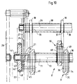
- the roller-shaped segments 49 shown in FIGS. 9 and 10 consist of symmetrically shaped, disk-shaped parts 34 which are connected by means of a pin 36 and over Circlips 37 held together and are additionally fixed off-center on the crossbar 11 via the latter.
- a ring 35 is rotatably mounted in a recess in the disk-shaped parts 34 made in the circumferential direction. As soon as the pressure plate 1 comes into contact with the circumferential surface of the rings 35 of the roller-shaped segments 49 employed, they roll on the pressure plate 1.
- the device for feeding and ejecting a printing plate 1 is screwed to the printing unit guard 29 via angled fastening parts 27 arranged on both sides.
- these fastening parts 29 are omitted in the top view according to FIGS. 9 and 10.
- the printing unit protection 29 is screwed to a lever 30 pivotably mounted about the axis 31.
- the printer In order to be able to carry out work on the printing unit, the printer must fold up the protection 29.
- the plate feed device is moved away at the same time, whereby unimpeded access to the printing unit, for example for cleaning purposes, is achieved.
- FIG. 11 a further on and off mechanism for the pair of rollers 8 is shown. With the exception of this mechanism, the other elements correspond to those from FIG. 9 or FIG. 10.
- a lever 46 is coupled to the roller pin 41 for pivoting the cross member 11.
- the lever 46 is assigned an actuating element 47 which, by applying a force F to the lever, performs the necessary actuating processes as a function of the angular position of the printing press.
- This control element is, for example, a lifting cylinder with two working positions or a magnet.
- An electric motor can of course also be used.
Landscapes
- Supply, Installation And Extraction Of Printed Sheets Or Plates (AREA)
Applications Claiming Priority (2)
| Application Number | Priority Date | Filing Date | Title |
|---|---|---|---|
| DE4414443A DE4414443C1 (de) | 1994-04-26 | 1994-04-26 | Vorrichtung zum Führen eines Druckträgers |
| DE4414443 | 1994-04-26 |
Publications (3)
| Publication Number | Publication Date |
|---|---|
| EP0679513A2 true EP0679513A2 (fr) | 1995-11-02 |
| EP0679513A3 EP0679513A3 (fr) | 1996-11-13 |
| EP0679513B1 EP0679513B1 (fr) | 2002-06-12 |
Family
ID=6516413
Family Applications (1)
| Application Number | Title | Priority Date | Filing Date |
|---|---|---|---|
| EP95104640A Expired - Lifetime EP0679513B1 (fr) | 1994-04-26 | 1995-03-29 | Procédé et dispositif de guidage d'un support d'impression |
Country Status (5)
| Country | Link |
|---|---|
| US (1) | US5738015A (fr) |
| EP (1) | EP0679513B1 (fr) |
| JP (1) | JP3790563B2 (fr) |
| CA (1) | CA2144194C (fr) |
| DE (2) | DE4414443C1 (fr) |
Cited By (4)
| Publication number | Priority date | Publication date | Assignee | Title |
|---|---|---|---|---|
| EP0712725A3 (fr) * | 1994-11-10 | 1996-06-05 | Roland Man Druckmasch | |
| EP1407881A1 (fr) * | 2002-10-11 | 2004-04-14 | MAN Roland Druckmaschinen AG | Procédé pour fixer et enlever une plaque d'impression flexible |
| WO2005007405A3 (fr) * | 2003-07-11 | 2005-06-23 | Koenig & Bauer Ag | Dispositifs et procedes pour appliquer et/ou retirer une matrice d'impression |
| DE102008019937A1 (de) | 2007-05-14 | 2008-11-20 | Heidelberger Druckmaschinen Ag | Vorrichtung zum Zuführen von Druckplatten zu einem Druckplattenzylinder |
Families Citing this family (12)
| Publication number | Priority date | Publication date | Assignee | Title |
|---|---|---|---|---|
| DE10238177B3 (de) * | 2002-08-21 | 2004-02-05 | Koenig & Bauer Ag | Vorrichtung zum Andrücken eines Aufzugs an einen Zylinder einer Druckmaschine mit Hilfe von in Umfangsrichtung des Zylinders voneinander beabstandeten ersten und zweiten Wälzelementen |
| GB9509479D0 (en) * | 1995-05-10 | 1995-07-05 | Btr Plc | Manipulation of printing blankets |
| US6113346A (en) | 1996-07-31 | 2000-09-05 | Agfa Corporation | Method for loading and unloading a supply of plates in an automated plate handler |
| JPH1120131A (ja) * | 1997-07-03 | 1999-01-26 | Ryobi Ltd | 印刷機の刷版咥え装置 |
| US6125757A (en) * | 1998-10-19 | 2000-10-03 | Heidelberger Druckmaschinen Ag | Method and apparatus for performing a flying printing plate change |
| JP2001260320A (ja) * | 2000-03-14 | 2001-09-25 | Fuji Photo Film Co Ltd | 可撓性刷版の装着方法および装着装置 |
| US6295929B1 (en) * | 2000-02-25 | 2001-10-02 | Agfa Corporation | External drum imaging system |
| DE10120952A1 (de) * | 2000-05-17 | 2001-11-22 | Heidelberger Druckmasch Ag | An- und abstellbare Leitelemente für das Auswechseln eines Druckträgers |
| DE10024329A1 (de) * | 2000-05-17 | 2001-11-22 | Koenig & Bauer Ag | Verfahren und Vorrichtungen zum Andrücken eines Aufzuges auf einen Zylinder |
| JP4383973B2 (ja) | 2004-06-25 | 2009-12-16 | リョービ株式会社 | 印刷機 |
| JP4498028B2 (ja) | 2004-06-25 | 2010-07-07 | リョービ株式会社 | 印刷機 |
| JP4426387B2 (ja) | 2004-06-25 | 2010-03-03 | リョービ株式会社 | 印刷機 |
Family Cites Families (20)
| Publication number | Priority date | Publication date | Assignee | Title |
|---|---|---|---|---|
| JPS5513912B2 (fr) * | 1972-07-24 | 1980-04-12 | ||
| JPS62169647A (ja) * | 1986-01-22 | 1987-07-25 | Mitsubishi Heavy Ind Ltd | 印刷機の版胴における版の尻側端部取外し装置 |
| JPS62169646A (ja) * | 1986-01-22 | 1987-07-25 | Mitsubishi Heavy Ind Ltd | 印刷機の版胴における版の尻側端部插入装置 |
| JPH07115462B2 (ja) * | 1988-01-06 | 1995-12-13 | 三菱重工業株式会社 | 刷版の版胴への着脱ロボット用ハンド |
| US5259314A (en) * | 1989-12-06 | 1993-11-09 | Komori Corporation | Plate mounting apparatus for printing press |
| DE3940796A1 (de) * | 1989-12-09 | 1991-06-13 | Koenig & Bauer Ag | Verfahren und einrichtung zum automatischen wechseln einer druckplatte |
| DE8915693U1 (de) * | 1989-12-09 | 1991-03-07 | Koenig & Bauer AG, 8700 Würzburg | Einrichtung zum automatischen Wechseln einer Druckplatte |
| DE3940795A1 (de) * | 1989-12-09 | 1991-06-13 | Koenig & Bauer Ag | Verfahren und einrichtung zum automatischen zufuehren bzw. abfuehren einer druckplatte |
| JP2844539B2 (ja) * | 1989-12-15 | 1999-01-06 | 株式会社小森コーポレーション | 印刷機の刷版保持装置 |
| DE4129831C3 (de) * | 1990-12-21 | 1998-08-13 | Heidelberger Druckmasch Ag | Schnellklemmvorrichtung |
| DE4128994A1 (de) * | 1990-12-31 | 1992-07-02 | Heidelberger Druckmasch Ag | Klemm- und spanneinrichtung |
| JP2570485Y2 (ja) * | 1991-06-24 | 1998-05-06 | 株式会社小森コーポレーション | 印刷機の刷版交換装置 |
| DE4218602C2 (de) * | 1991-08-28 | 1993-11-11 | Heidelberger Druckmasch Ag | Vorrichtung zum Einführen der Druckplattenhinterkante an einem Plattenzylinder |
| EP0530577B1 (fr) * | 1991-08-31 | 1996-06-19 | Heidelberger Druckmaschinen Aktiengesellschaft | Dispositif pour positionner un chargeur servant au remplacement automatique des plaques d'impression |
| DE4130359C2 (de) * | 1991-09-12 | 1997-04-17 | Heidelberger Druckmasch Ag | Vorrichtung zum Ab- und/oder Zuführen von Druckplatten einer Druckmaschine |
| US5272977A (en) * | 1992-02-05 | 1993-12-28 | Toshiba Kikai Kabushiki Kaisha | Printing plate mounting apparatus, printing plate replacement apparatus and printing plate replacement method |
| DE4214047A1 (de) * | 1992-04-29 | 1993-11-04 | Heidelberger Druckmasch Ag | Halteeinrichtung fuer eine zu verschiebende platte |
| DE4231906C2 (de) * | 1992-09-18 | 1995-10-12 | Koenig & Bauer Ag | Einrichtung zum Zuführen und Abführen von Druckplatten zu und von einem Plattenzylinder |
| DE59304916D1 (de) * | 1992-09-18 | 1997-02-06 | Koenig & Bauer Albert Ag | Verfahren zum zuführen von druckplatten |
| DE4309658C1 (de) * | 1993-03-25 | 1994-10-27 | Roland Man Druckmasch | Vorrichtung zum automatischen Wechseln von Druckplatten bei Bogenoffsetdruckmaschinen mit mehreren Druckwerken |
-
1994
- 1994-04-26 DE DE4414443A patent/DE4414443C1/de not_active Expired - Fee Related
-
1995
- 1995-03-08 CA CA002144194A patent/CA2144194C/fr not_active Expired - Fee Related
- 1995-03-29 DE DE59510234T patent/DE59510234D1/de not_active Expired - Lifetime
- 1995-03-29 EP EP95104640A patent/EP0679513B1/fr not_active Expired - Lifetime
- 1995-04-19 JP JP09358895A patent/JP3790563B2/ja not_active Expired - Fee Related
-
1996
- 1996-12-23 US US08/772,975 patent/US5738015A/en not_active Expired - Lifetime
Cited By (7)
| Publication number | Priority date | Publication date | Assignee | Title |
|---|---|---|---|---|
| EP0712725A3 (fr) * | 1994-11-10 | 1996-06-05 | Roland Man Druckmasch | |
| US5617792A (en) * | 1994-11-10 | 1997-04-08 | Man Roland Druckmaschinen Ag | Roller element for pressing a flexible printing plate onto the form cylinder |
| EP1407881A1 (fr) * | 2002-10-11 | 2004-04-14 | MAN Roland Druckmaschinen AG | Procédé pour fixer et enlever une plaque d'impression flexible |
| WO2005007405A3 (fr) * | 2003-07-11 | 2005-06-23 | Koenig & Bauer Ag | Dispositifs et procedes pour appliquer et/ou retirer une matrice d'impression |
| US7464644B2 (en) | 2003-07-11 | 2008-12-16 | Koenig & Bauer Aktiengesellschaft | Devices and methods for raising and/or lowering a printing form |
| US7690302B2 (en) | 2003-07-11 | 2010-04-06 | Koenig & Bauer Aktiengesellsschaft | Device and methods for raising and/or lowering a printing form |
| DE102008019937A1 (de) | 2007-05-14 | 2008-11-20 | Heidelberger Druckmaschinen Ag | Vorrichtung zum Zuführen von Druckplatten zu einem Druckplattenzylinder |
Also Published As
| Publication number | Publication date |
|---|---|
| DE59510234D1 (de) | 2002-07-18 |
| US5738015A (en) | 1998-04-14 |
| DE4414443C1 (de) | 1995-11-30 |
| JPH07290690A (ja) | 1995-11-07 |
| CA2144194A1 (fr) | 1995-10-27 |
| CA2144194C (fr) | 1999-06-01 |
| JP3790563B2 (ja) | 2006-06-28 |
| EP0679513B1 (fr) | 2002-06-12 |
| EP0679513A3 (fr) | 1996-11-13 |
Similar Documents
| Publication | Publication Date | Title |
|---|---|---|
| EP0679513B1 (fr) | Procédé et dispositif de guidage d'un support d'impression | |
| DE2649052C2 (de) | Vorrichtung zum Ausschalten des Lagerspiels an Druckzylindern von Druckmaschinen, insbesondere Rotationsoffsetdruckmaschinen | |
| DE4335140C1 (de) | Vorrichtung zum Befestigen einer biegsamen Druckplatte | |
| EP1101612B1 (fr) | Procédé et dispositif pour mettre en place automatiquement d'une plaque sur un cylindre porte-plaque d'une presse à imprimer rotative | |
| DE2833745A1 (de) | Lithographische einrichtung | |
| DE69303916T2 (de) | Vorrichtung zum Wechseln von Druckplatten in einer Druckmaschine | |
| DE4416296C2 (de) | Vorrichtung zum Aufziehen flexibler Druckformen | |
| CH620157A5 (fr) | ||
| EP0706884A1 (fr) | Dispositif pour alimenter des plaques d'impression | |
| EP0704302B1 (fr) | Dispositif pour alimenter une plaque d'impression vers le cylindre porte-plaque d'une machine à imprimer | |
| DE3413943C2 (de) | Bogenauslagevorrichtung, insbesondere für Kleinoffsetmaschinen | |
| EP0995596B1 (fr) | Dispositif et procédé pour la mise en oeuvre d'un changement de plaques en marche | |
| DE69510318T2 (de) | Fixiervorrichtung für den Anfang eines Druckblattes mit Vorrichtung zum Anheben des freigegebenen Blattanfangs | |
| DE3880697T2 (de) | Farbvorrichtung fuer druckmaschine. | |
| DE2045148A1 (fr) | ||
| DE3320552A1 (de) | Offset-druckpresse mit zwei druckwerken | |
| DE2358223A1 (de) | Umfuehrtrommel mit einrichtungen zur erfassung der bogenvorder- und bogenhinterkante fuer druckmaschinen | |
| EP0275882A2 (fr) | Dispositif de transport pour une machine d'impression rotative à feuilles | |
| DE10018923A1 (de) | Druckmaschine mit einem Andrückelement und einer Schutzeinrichtung | |
| DE19538322C2 (de) | Einrichtung zur axialen Verstellung von Leitelementen | |
| DE4340079C2 (de) | Offset-Druckmaschine mit einer Numeriereinheit | |
| DE1118807B (de) | Einrichtung zum Befestigen von Bogen an den Druckzylindern von Druckmaschinen, insbesondere von Rotationsvervielfaeltigern | |
| DE102017201161B4 (de) | Verfahren zum Aufziehen einer Platte auf einen Zylinder einer Druckmaschine und eine Vorrichtung zum Aufziehen einer Platte in einer Druckmaschine | |
| DE1571863C3 (fr) | ||
| DE2941904C2 (de) | Vorrichtung zum Bedrucken von Gegenständen, insbesondere von etikettierten Behältern in Etikettiermaschinen |
Legal Events
| Date | Code | Title | Description |
|---|---|---|---|
| PUAI | Public reference made under article 153(3) epc to a published international application that has entered the european phase |
Free format text: ORIGINAL CODE: 0009012 |
|
| 17P | Request for examination filed |
Effective date: 19950329 |
|
| AK | Designated contracting states |
Kind code of ref document: A2 Designated state(s): DE FR GB IT |
|
| GBC | Gb: translation of claims filed (gb section 78(7)/1977) | ||
| PUAL | Search report despatched |
Free format text: ORIGINAL CODE: 0009013 |
|
| AK | Designated contracting states |
Kind code of ref document: A3 Designated state(s): DE FR GB IT |
|
| 17Q | First examination report despatched |
Effective date: 19980401 |
|
| RTI1 | Title (correction) |
Free format text: METHOD AND DEVICE FOR GUIDING A PRINTING SUPPORT |
|
| RTI1 | Title (correction) |
Free format text: METHOD AND DEVICE FOR GUIDING A PRINTING SUPPORT |
|
| GRAG | Despatch of communication of intention to grant |
Free format text: ORIGINAL CODE: EPIDOS AGRA |
|
| GRAG | Despatch of communication of intention to grant |
Free format text: ORIGINAL CODE: EPIDOS AGRA |
|
| GRAH | Despatch of communication of intention to grant a patent |
Free format text: ORIGINAL CODE: EPIDOS IGRA |
|
| GRAH | Despatch of communication of intention to grant a patent |
Free format text: ORIGINAL CODE: EPIDOS IGRA |
|
| GRAA | (expected) grant |
Free format text: ORIGINAL CODE: 0009210 |
|
| AK | Designated contracting states |
Kind code of ref document: B1 Designated state(s): DE FR GB IT |
|
| REG | Reference to a national code |
Ref country code: GB Ref legal event code: FG4D Free format text: NOT ENGLISH |
|
| REF | Corresponds to: |
Ref document number: 59510234 Country of ref document: DE Date of ref document: 20020718 |
|
| GBT | Gb: translation of ep patent filed (gb section 77(6)(a)/1977) |
Effective date: 20020806 |
|
| ET | Fr: translation filed | ||
| PGFP | Annual fee paid to national office [announced via postgrant information from national office to epo] |
Ref country code: GB Payment date: 20030224 Year of fee payment: 9 |
|
| PGFP | Annual fee paid to national office [announced via postgrant information from national office to epo] |
Ref country code: FR Payment date: 20030320 Year of fee payment: 9 |
|
| PLBE | No opposition filed within time limit |
Free format text: ORIGINAL CODE: 0009261 |
|
| STAA | Information on the status of an ep patent application or granted ep patent |
Free format text: STATUS: NO OPPOSITION FILED WITHIN TIME LIMIT |
|
| 26N | No opposition filed |
Effective date: 20030313 |
|
| PG25 | Lapsed in a contracting state [announced via postgrant information from national office to epo] |
Ref country code: GB Free format text: LAPSE BECAUSE OF NON-PAYMENT OF DUE FEES Effective date: 20040329 |
|
| GBPC | Gb: european patent ceased through non-payment of renewal fee |
Effective date: 20040329 |
|
| PG25 | Lapsed in a contracting state [announced via postgrant information from national office to epo] |
Ref country code: FR Free format text: LAPSE BECAUSE OF NON-PAYMENT OF DUE FEES Effective date: 20041130 |
|
| REG | Reference to a national code |
Ref country code: FR Ref legal event code: ST |
|
| PG25 | Lapsed in a contracting state [announced via postgrant information from national office to epo] |
Ref country code: IT Free format text: LAPSE BECAUSE OF NON-PAYMENT OF DUE FEES;WARNING: LAPSES OF ITALIAN PATENTS WITH EFFECTIVE DATE BEFORE 2007 MAY HAVE OCCURRED AT ANY TIME BEFORE 2007. THE CORRECT EFFECTIVE DATE MAY BE DIFFERENT FROM THE ONE RECORDED. Effective date: 20050329 |
|
| PGFP | Annual fee paid to national office [announced via postgrant information from national office to epo] |
Ref country code: DE Payment date: 20120411 Year of fee payment: 18 |
|
| REG | Reference to a national code |
Ref country code: DE Ref legal event code: R119 Ref document number: 59510234 Country of ref document: DE Effective date: 20131001 |
|
| PG25 | Lapsed in a contracting state [announced via postgrant information from national office to epo] |
Ref country code: DE Free format text: LAPSE BECAUSE OF NON-PAYMENT OF DUE FEES Effective date: 20131001 |