EP1101612B1 - Procédé et dispositif pour mettre en place automatiquement d'une plaque sur un cylindre porte-plaque d'une presse à imprimer rotative - Google Patents
Procédé et dispositif pour mettre en place automatiquement d'une plaque sur un cylindre porte-plaque d'une presse à imprimer rotative Download PDFInfo
- Publication number
- EP1101612B1 EP1101612B1 EP00123303A EP00123303A EP1101612B1 EP 1101612 B1 EP1101612 B1 EP 1101612B1 EP 00123303 A EP00123303 A EP 00123303A EP 00123303 A EP00123303 A EP 00123303A EP 1101612 B1 EP1101612 B1 EP 1101612B1
- Authority
- EP
- European Patent Office
- Prior art keywords
- plate
- cylinder
- printing plate
- grippers
- printing
- Prior art date
- Legal status (The legal status is an assumption and is not a legal conclusion. Google has not performed a legal analysis and makes no representation as to the accuracy of the status listed.)
- Expired - Lifetime
Links
- 238000007639 printing Methods 0.000 title claims abstract description 62
- 238000000034 method Methods 0.000 title claims abstract description 23
- 238000007645 offset printing Methods 0.000 claims description 7
- 238000006073 displacement reaction Methods 0.000 claims 1
- 230000007246 mechanism Effects 0.000 description 9
- 238000003780 insertion Methods 0.000 description 7
- 230000037431 insertion Effects 0.000 description 7
- 230000007257 malfunction Effects 0.000 description 2
- 230000000712 assembly Effects 0.000 description 1
- 238000000429 assembly Methods 0.000 description 1
- 238000002360 preparation method Methods 0.000 description 1
Images





Classifications
-
- B—PERFORMING OPERATIONS; TRANSPORTING
- B41—PRINTING; LINING MACHINES; TYPEWRITERS; STAMPS
- B41F—PRINTING MACHINES OR PRESSES
- B41F27/00—Devices for attaching printing elements or formes to supports
- B41F27/12—Devices for attaching printing elements or formes to supports for attaching flexible printing formes
- B41F27/1206—Feeding to or removing from the forme cylinder
-
- B—PERFORMING OPERATIONS; TRANSPORTING
- B41—PRINTING; LINING MACHINES; TYPEWRITERS; STAMPS
- B41P—INDEXING SCHEME RELATING TO PRINTING, LINING MACHINES, TYPEWRITERS, AND TO STAMPS
- B41P2227/00—Mounting or handling printing plates; Forming printing surfaces in situ
- B41P2227/60—Devices for transferring printing plates
Definitions
- the present invention relates to a method and an apparatus for automatic Applying a printing plate to a plate cylinder in a rotary printing press according to the preamble of claims 1 and 12.
- Document US-A-5 595 119 is considered the closest prior art.
- the US-A-5 595 119 describes a method of an automatic device Printing plate change in a rotary printing machine, with a new printing plate 80U is stored in a swiveling cassette 30U.
- the cassette 30U will pivoted such that its lower end is positioned in the vicinity of a pressure roller 28U which is located opposite the surface of a plate cylinder 13U.
- a pneumatic cylinder 61U is activated, so that a gripper 60, which the the rear end of the plate 80U holds along the cassette toward the platen roller 28U is moved. This movement stops as soon as a leading edge 81U reaches a position reached at the pressure roller 28U.
- the pressure roller 28U presses the front edge 81U in a clamping gap of the plate cylinder 13U.
- the Press roller 28U becomes the cleat nip for holding the plate leading edge 81U closed.
- document WO-A-95/19262 discloses a device for assembly, Disassembly and transport of printing plates on and from a cylinder Rotary printing press.
- a plate-mounted, plate-fixed printing plate supply device provided with at least one pre-positioned pressure plate, and a traverse with at least one gripping and pressing device, which in one Transport plane is positioned by means of a linear drive, the Transport plane approximately parallel and above to one of a cylinder surface of the cylinder and mounting rail of the printing plate preparation device Tangent lies.
- No. 5,390,603 discloses a method for automatically changing printing plates described a plate cylinder of a printing press.
- the plate cylinder includes one Fastening or clamping device for the front edge and the rear edge of one Printing plate.
- the plate cylinders are placed in a Change position moves in the trailing edge and the leading edge of the printing plates be released. Then the plate cylinders are placed in the opposite Direction turned to unroll the pressure plate. Then each plate cylinder a new pressure plate is fed by means of suction arms, the suction arms feeding the pressure plate in such a way that the leading edge of the new plate is attached to the leading edge fastening device can be attached.
- US 5,495,805 and US 5,443,006 describe feed and discharge devices from printing plates to or from a plate cylinder. That in these patents described magazine comprises two holding shafts, inserted into the cassettes from above can be. One of the cassettes is for holding the used printing plates originally empty, while in another cassette the on the plate cylinder new printing plates to be applied are included. A plate feeder removes the plates from the cassette containing the new plates. A Plate path guiding device removes the plates from the plate cylinder and places them in the Cassette for the old records.
- the plate path guide includes suction elements that on a by means of a first drive device along a first guide movable first carriage are arranged.
- the Trailing edge clamping device opened so that the elasticity of the pressure plate Impacts the rear edge against a guide roller.
- the plate cylinder will then turned backwards so that the plate is inserted into the magazine. in the Magazine, the suction elements are activated.
- the old printing plate Suction elements of the first carriage moved to an upper position during the Plate cylinder continues to be rotated backwards.
- the old plate is then placed in the Cassette for old printing plates inserted.
- the includes Plate feed mechanism a second carriage with suction elements.
- the leading edge of the new printing plate is moved to the leading edge clamping device of the plate cylinder.
- the plate is aligned and clamped.
- the plate cylinder rotated forward so that the pressure plate is around the outer surface of the plate cylinder is placed.
- the pressure plate can be reduced by reducing the suction power of the suction elements continue to be held by the suction elements, while due to the rotation of the Plate cylinder slides over this.
- the rear edge of the pressure plate passes the last two suction elements, they are deactivated and the rear edge of the Pressure plate radially into the trailing edge clamping device by means of a pressure roller pressed. Then the rear edge is clamped and the plate is stretched.
- U 5,701,822 there is a plate changing device for an offset printing machine described.
- the plate cylinder comprises an automatic clamping device in one Gap or channel of the plate cylinder.
- a holding element is provided to support the positioning of the Pressure plate on the plate cylinder.
- the one to apply Printing plate is held by a printing plate loading unit.
- the holding element detects the plate to be inserted and positions the front edge on the plate cylinder.
- the printing form can then by the Circumferential surface of the plate cylinder can be clamped.
- a disadvantage of the devices and methods described is that the The front edge of the plate cylinder can slip, so that it does not slide before insertion is aligned more along the cylinder channel. This can cause the malfunction automatic plate changing device. Especially with plate cylinders The methods and devices described frequently lead to a very small cylinder gap malfunction or cannot be used at all.
- US 5,553,544 and US 5,284,093 describe plate cylinders with a narrow one Cylinder gap in which both the front edge and the rear edge of the pressure plate be inserted so that there is only a small space between them.
- US 5,678,487 is also a plate cylinder with a narrow cylinder gap and one Trailing edge insertion device described.
- An object of the present invention is to provide an improved method and an improved device for the automatic application of printing plates on a To create plate cylinders in a rotary printing press.
- the method according to the invention for automatically applying a printing plate a plate cylinder provides a first edge against a printing plate a cylinder adjoining the plate cylinder and thereby aligned the first edge of the printing plate into a gap or channel in the plate cylinder is inserted and the printing plate is then placed around the plate cylinder becomes.
- the inventive method is a better alignment of the plate before Inserted into the cylinder gap or channel reached. This allows the front edge of the Plate inserted reliably and correctly aligned in the cylinder gap or channel be, which means even with plate cylinders with a very narrow gap reliable application of the plate is made possible.
- the method according to the invention comprises fastening the first edge in the cylinder gap.
- the plate cylinder is then preferably rotated, so that the plate is placed around the plate cylinder.
- An insertion device can then be used to insert the trailing edge of the plate into the gap support.
- the adjacent cylinder is preferably one by a blanket cylinder Offset printing press formed. This offers a large adjacent area on which the Plate can be aligned.
- the inventive device for applying a printing plate on a Plate cylinder comprises a first gripper arrangement for gripping one Pressure plate and for aligning the pressure plate on one to the plate cylinder adjacent cylinder, and a second gripper assembly for moving the plate in Direction of a gap or channel formed in the plate cylinder.
- the first gripper arrangement comprises resilient grippers that enable the plate to be aligned with the adjacent cylinder, the first gripper arrangement preferably exclusively in the radial direction adjacent cylinder is movable.
- the second gripper arrangement is preferably in a direction essentially radial to the plate cylinder.
- the device preferably comprises an insertion device for inserting the Trailing edge of the pressure plate in the gap or channel.
- the present invention also preferably provides an offset printing machine that has one Plate cylinder with plate clamping device and one in the cylinder surface formed receiving gap or channel, a blanket cylinder, which with the Plate cylinder forms a gap, and comprises a plate applicator, the one first gripper arrangement for gripping the pressure plate and for aligning the pressure plate on the blanket cylinder and a second gripper arrangement for moving the printing plate has in the direction of the receiving gap.
- Fig. 1 shows a schematic side view of an inventive Plate application device 10, the first gripper assembly 20, a second Gripper assembly 30 and an insertion device 40 comprises.
- the Plate application device is arranged adjacent to an offset printing unit 1, which a plate cylinder 2, an adjacent to this upper blanket cylinder 3 and comprises a lower blanket cylinder or impression cylinder 4.
- an offset printing unit 1 which a plate cylinder 2, an adjacent to this upper blanket cylinder 3 and comprises a lower blanket cylinder or impression cylinder 4.
- a Plate clamping device 5 which is a plate clamping device 6 in the direction of Plate cylinder surface or moved away from this.
- the jig can for example similar to that in US 5,284,093, US 5,553,544 and US 5,678,487 described clamping device be formed.
- Between the side wall of the Cylinder channel or gap and the plate clamping device 6 is preferably a Gap 7, in which a leading edge 62 and a trailing edge 64 of a pressure plate 60 can be recorded.
- the first gripper arrangement comprises at least one first gripper 22, which is preferably in a gripper holder 24 between a first spring 26 and a second spring 27 is held.
- the first gripper arrangement is preferably in a guide rail 28 movable and can record and hold the plate 60, for example by suction.
- the first gripper 22 moves in the guide rail 28 in such a way that the plate 60 is moved radially with respect to the blanket cylinder 3.
- the first gripper 22 is thereby of springs or generally resilient means 26 and 27 in the manner held that it is slightly flexible radially in the direction of the springs, but in the axial direction, i.e. H. 1 in the direction of the plane of the drawing, and tangential to the blanket cylinder 3 is immobile or stationary.
- the grippers can have a vacuum device and a connected flexible pipe connection with suction air.
- the Suction pads can for example be similar to those described in US 5,443,006 Suction attachments can be formed.
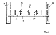
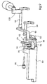
- FIG. 7 shows a cross-sectional view of the first gripper arrangement 20, in which it is clear that the gripper arrangement 20 is preferably a plurality of (through which dotted lines indicated) grippers 22, 23 and 29 includes between springs being held.
- the gripper holder 24 can be designed as a horizontal bar, which is movable in the guide rail 28.
- the gripper bracket 24 is preferred driven by gear wheels driven by a motor.
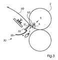
- the gripper holder 24 is radially in the direction of the Blanket cylinder 3 moves that its leading edge 62 in its entirety Blanket cylinder 3 contacted. Doing so will result in misalignment or a shift the leading edge 62 with respect to the blanket cylinder 3, as in devices of the State of the art can occur, corrected by the springs 26 and 27, by which the front edge 62 is aligned on the surface of the blanket cylinder 3. On in this way, the front edge 62 on the parallel to the blanket cylinder 3rd extending plate cylinder 2 aligned. Accordingly, after the alignment process both the front edge 62 and the axis 102 of the plate cylinder 2 and the axis 103 of the blanket cylinder 3 all arranged parallel to each other.
- the second gripper arrangement 30 with a gripper 31, one second gripper holder 32 and a guide rail 33 in such a way that they can grip plate 60 in its correctly aligned position.
- the plate 60 for example, by means of suction in its aligned position.
- the first gripper assembly 20 then releases the plate 60 free by lifting the suction or z. B. a blown air flow is generated.
- the gripper holder 32 is then in the guide rail 33 in the way that the leading edge 62 of the plate 60 in the space 7 on the open clamping device 5 of the plate cylinder 2 is inserted, the Plate cylinder is in a first application position.
- the guide rail 33 runs preferably arcuate, so that the plate is inserted at a suitable angle.
- the guide rail 33 can also be shaped such that the front edge 62 initially rests on the surface of the clamping device 6. This will make the plate 60 bent backwards due to their flexibility and in this way preferably with a resilient force is applied.
- the plate 60 can then be moved along the Surface of the clamping device 6 are moved upwards, so that the front edge of the The plate automatically jumps into space 7.
- the grippers 31 are preferably in the axial direction, i. H. 2, 3 and 4 perpendicular to Drawing level, resiliently arranged.
- the entire gripper arrangement 30 is also axial movable, e.g. B. by means of a linear drive for the guide rail 33 in the axial Direction.
- the clamping device 5 is then closed and the suction force lifted or a blast air flow generated, so that the second gripper assembly 30 the Plate 60 releases. In this way, the plate 60 is correctly aligned in the Space 7 fixed.
- the plate cylinder 2 is then in the in Fig. 4 by the Arrow indicated direction rotated to the plate 60 on the plate cylinder 2nd
- the plate 60 is covered by the gap between the Plate cylinder and the blanket cylinder and can be pulled through the deactivated gripper 31 are additionally supported.
- the gripper 31 can also retracted when the inherent rigidity of the plate 60 is sufficient to be a Prevent damage from components of the plate applicator 10.
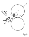
- the trailing edge 64 is in the intermediate space 7 introduced.
- the plate clamping device 6 is activated and from the surface of the plate cylinder 2 moved away.
- the insertion device 40, the z. B. similar to that in the Inserting device described in US Pat. No. 5,678,487 can be activated and activated moves or pushes the trailing edge 64 into the space 7. Then preferably the clamping device 6 is withdrawn and the insertion device 40 deactivated so that the plate 60 is firmly attached to the plate cylinder 2.
- Removing plate 60 after a print job can be done in several ways take place, e.g. B. by means of a preferably on the other side of the plate cylinder arranged automatic removal device or by means of Plate application device 10, which guides the plate away from the plate cylinder 2.
- the second gripper arrangement is arranged on the gripper holder 24 shown in FIG. 7 his.
- the gripper holder 24 can be inserted the plate after its alignment on the blanket cylinder are turned upwards.
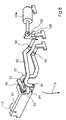
- a rod mechanism can also be provided, as shown in FIG. 8 and 9 is shown.
- the two gripper assemblies 20 and 30 can be on one Gripper bracket 80 may be attached, the second gripper assembly 30 preferably is arranged below the first gripper arrangement 20, as shown in FIG. 10.
- the holder 80 is preferably at its lower end via a pivot 82 an air cylinder bracket 84 and a first arm 90 of the rod mechanism connected. At its upper end, the holder 80 is connected via a pivot pin 88 (FIG. 9) connected to one side of a lever 94 of the rod mechanism. The other side of the Lever 94 is via a pivot 95 with one end 93 of a second arm 92 connected. The pivot 95 is in turn with a on the air cylinder bracket 84 stored compressed air cylinder 96 connected.
- the arms 90 and 92 are preferably at their ends 98 and 99 z. B. in a frame rotatably mounted.
- An operating arm 100 for moving the first arm 90 is on one End 98 of the first arm 90 and one end of the other Air cylinder 104 connected.
- a similar rod mechanism is arranged on the other side of the holder 80.
- the operation of the rod mechanism is explained below.
- the first Gripper assembly 20 grips a plate from a plate supply.
- the compressed air cylinder 102 is activated so that arm 90 turns in the direction indicated by arrow 108 its end 98 is rotated. This will make the gripper bracket 80 down in the direction of the arrow 110 pivoted so that the plate against the Surface of the blanket cylinder is moved and aligned with this. Subsequently the plate is gripped by the second gripper arrangement 30 and by the first Gripper assembly 20 released.
- the compressed air cylinder 96 is then activated so that the gripper holder 80 rotated in the direction of arrow 112 and the plate edge against the terminal block or the surface of the plate cylinder is moved.
- the plate jumps into the cylinder channel or gap and is then axially aligned in the manner described above, preferably by adding the entire rod mechanism over others not shown Actuators, e.g. B. a pneumatic cylinder is moved axially. Following that activated the plate clamping device in the plate cylinder and the plate from the Gripper assembly 30 released.
- Actuators e.g. B. a pneumatic cylinder is moved axially.
- the second air cylinder 96 can also be used to grip new plates to support from a plate stock.
- the plate cylinder 2 can be used as a plate cylinder with a narrow channel or gap be trained, which means in the sense of this application that the cylinder channel is narrower than about 0.635 cm (0.25 inches).
- the blanket cylinder is used to align the plate.
- another cylinder adjacent to the plate cylinder e.g. B. an ink roller or dampening roller, for aligning the plate before inserting it into the cylinder channel use.
- On the blanket cylinder there is preferably a channelless blanket applied, which gives the advantage that the plate edge during the Alignment cannot enter a blanket channel, which leads to an error in the Alignment can result.
- the term "gripper arrangement” denotes in this Registration at least one gripper that is suitable for the activated in the To hold the pressure plate.
Landscapes
- Supply, Installation And Extraction Of Printed Sheets Or Plates (AREA)
- Rotary Presses (AREA)
- Coating Apparatus (AREA)
Claims (17)
- Procédé pour mettre en place automatiquement une plaque imprimante (60) sur un cylindre porte-plaque (2) d'une presse à imprimer rotative, avec les étapes de procédé suivantes :caractérisé par l'étape de procédé suivante :insérer une première arête (62) de la plaque imprimante (60) dans un interstice (7) formé dans le cylindre porte-plaque (2), etmonter la plaque imprimante (60) sur le cylindre porte-plaque (2),aligner la première arête (62) de la plaque imprimante (60) sur la surface d'un cylindre (3) contigu au cylindre porte-plaque (2).
- Procédé selon la revendication 1, caractérisé en ce que durant le montage de la plaque imprimante (60), on tourne le cylindre porte-plaque (2) de telle sorte que ladite plaque imprimante (60) passe un interstice formé entre le cylindre porte-plaque (2) et le cylindre (3) contigu.
- Procédé selon l'une quelconque des revendications précédentes, caractérisé en ce que le cylindre (3) contigu constitue un cylindre du blanchet d'une presse à imprimer rotative offset.
- Procédé selon l'une quelconque des revendications précédentes, caractérisé en ce que l'alignement de la première arête (62) de la plaque imprimante (60) au cylindre (3) contigu s'effectue par mise en pression de ladite plaque imprimante (60) par des moyens à déformation et par mouvement de ladite plaque imprimante (60) dans une direction essentiellement radiale par rapport à la surface périphérique du cylindre (3) contigu.
- Procédé selon l'une quelconque des revendications précédentes, caractérisé en ce que la plaque imprimante (60), suite à l'alignement de la première arête (62) au cylindre (3) contigu, est pivotée de manière essentiellement tangentielle en direction du cylindre porte-plaque (2).
- Procédé selon l'une quelconque des revendications précédentes, caractérisé en ce que la plaque imprimante (60), suite à l'introduction de la première arête (62) dans l'interstice (7) du cylindre porte-plaque (2), est déplacée dans une direction axiale par rapport audit cylindre porte-plaque (2), dans le but de positionner ladite plaque imprimante (60) sur ledit cylindre porte-plaque (2).
- Procédé selon la revendication 6, caractérisé en ce que la plaque imprimante (60), en vue du déplacement axial, est mise en pression par l'intermédiaire de moyens à déformation (26, 27).
- Procédé selon l'une quelconque des revendications précédentes, caractérisé en ce que la plaque imprimante (60), en vue de l'alignement de la première arête (62), est maintenue par un premier preneur (20) et déplacée en direction du cylindre (3) contigu.
- Procédé selon la revendication 8, caractérisé en ce que la plaque imprimante (60), suite à l'alignement de la première arête (62), est saisie au niveau du cylindre (3) contigu par un deuxième preneur (30) et déplacée en direction de l'interstice (7) du cylindre porte-plaque (2).
- Procédé selon la revendication 9, caractérisé en ce que le premier preneur (20), suite à la saisie par le deuxième preneur (30), libère la plaque imprimante (60).
- Procédé selon la revendication 9 ou 10, caractérisé en ce que le deuxième preneur (30) déplace la plaque imprimante (60) depuis le cylindre (3) contigu en direction du cylindre porte-plaque (2), de telle sorte que la première arête (62) de ladite plaque imprimante (60) épouse ledit cylindre porte-plaque (2).
- Dispositif pour mettre en place une plaque imprimante (60) sur un cylindre porte-plaque (2), avec un premier preneur (20) destiné à la prise de ladite plaque imprimante (60) et au déplacement de celui-ci (60) en direction d'un cylindre (3) contigu audit cylindre porte-plaque (2), et avec un deuxième preneur (30) destiné au déplacement de ladite plaque imprimante (60) en direction d'un interstice (7) constitué dans ledit cylindre porte-plaque (2), caractérisé en ce que le premier preneur (20) est mis en pression à l'aide d'une force élastique par le biais de moyens à déformation (26, 27) dans une direction sensiblement radiale par rapport au cylindre (3) contigu au cylindre porte-plaque (2), en vue de l'alignement de la plaque imprimante (60) sur la surface dudit cylindre (3) contigu audit cylindre porte-plaque (2).
- Dispositif selon la revendication 12, caractérisé en ce que le premier preneur (20) est guidé par une première coulisse de guidage (28) longeant sensiblement de façon radiale le cylindre (3) contigu.
- Dispositif selon l'une quelconque des revendications 12 à 13, caractérisé en ce que le deuxième preneur (30) est guidé par une deuxième coulisse de guidage (33) disposée dans un sens sensiblement radial par rapport au cylindre porte-plaque (2).
- Dispositif selon l'une quelconque des revendications 12 à 14, caractérisé en ce que le deuxième preneur (30) peut être déplacé dans un sens axial par rapport au cylindre porte-plaque (2).
- Dispositif selon l'une quelconque des revendications 12 à 15, caractérisé en ce que le premier preneur (20) et/ou le deuxième preneur (30) comprend (comprennent) un ou plusieurs preneurs aspirants.
- Groupe imprimant offset, caractérisé par un dispositif selon l'une des revendications 12 à 16.
Applications Claiming Priority (2)
| Application Number | Priority Date | Filing Date | Title |
|---|---|---|---|
| US09/444,801 US6460457B1 (en) | 1999-11-22 | 1999-11-22 | Method and device for automatically providing a printing plate to a plate cylinder |
| US444801 | 2003-05-23 |
Publications (3)
| Publication Number | Publication Date |
|---|---|
| EP1101612A2 EP1101612A2 (fr) | 2001-05-23 |
| EP1101612A3 EP1101612A3 (fr) | 2002-03-27 |
| EP1101612B1 true EP1101612B1 (fr) | 2004-12-22 |
Family
ID=23766419
Family Applications (1)
| Application Number | Title | Priority Date | Filing Date |
|---|---|---|---|
| EP00123303A Expired - Lifetime EP1101612B1 (fr) | 1999-11-22 | 2000-10-26 | Procédé et dispositif pour mettre en place automatiquement d'une plaque sur un cylindre porte-plaque d'une presse à imprimer rotative |
Country Status (5)
| Country | Link |
|---|---|
| US (1) | US6460457B1 (fr) |
| EP (1) | EP1101612B1 (fr) |
| JP (1) | JP4638587B2 (fr) |
| AT (1) | ATE285328T1 (fr) |
| DE (1) | DE50009015D1 (fr) |
Families Citing this family (19)
| Publication number | Priority date | Publication date | Assignee | Title |
|---|---|---|---|---|
| US6595135B2 (en) * | 2001-05-07 | 2003-07-22 | Heidelberger Druckmaschinen Ag | Printing unit with automatically moveable tail tucker bar |
| EP1453678B1 (fr) * | 2001-11-28 | 2005-04-20 | Koenig & Bauer Aktiengesellschaft | Dispositifs et procedes permettant l'alignement ou le montage d'un habillage applique sur un cylindre d'une imprimante |
| JP4044359B2 (ja) * | 2002-04-12 | 2008-02-06 | 株式会社小森コーポレーション | 版挿入装置 |
| JP2005199471A (ja) * | 2004-01-13 | 2005-07-28 | Riso Kagaku Corp | 孔版印刷装置 |
| JP4904018B2 (ja) * | 2004-05-04 | 2012-03-28 | ハイデルベルガー ドルツクマシーネン アクチエンゲゼルシヤフト | 刷版搬送のための方法及び装置 |
| US7366942B2 (en) * | 2004-08-12 | 2008-04-29 | Micron Technology, Inc. | Method and apparatus for high-speed input sampling |
| US7849796B2 (en) * | 2005-03-30 | 2010-12-14 | Goss International Americas, Inc | Web offset printing press with articulated tucker |
| US7819057B2 (en) | 2005-03-30 | 2010-10-26 | Goss International Americas, Inc. | Print unit having blanket cylinder throw-off bearer surfaces |
| WO2006104827A2 (fr) * | 2005-03-30 | 2006-10-05 | Goss International Americas, Inc. | Presse a imprimer sur rotative offset a galvanoplastie automatique |
| CN101631679B (zh) | 2005-03-30 | 2011-12-07 | 高斯国际美洲公司 | 悬臂式胶印滚筒提升机构 |
| CN101163589B (zh) | 2005-04-11 | 2010-05-19 | 高斯国际美洲公司 | 允许自动装版的具有单个电动机驱动的印刷单元 |
| GB2425987A (en) * | 2005-05-09 | 2006-11-15 | Goss Graphic Systems Ltd | Printing plate unloading apparatus and method |
| US20070022885A1 (en) * | 2005-07-27 | 2007-02-01 | Goss International Americas, Inc. | Method and apparatus for preventing plate cylinder contamination during a plating process |
| GB2428634B (en) * | 2005-08-04 | 2008-09-17 | Goss Graphic Systems Ltd | Printing press |
| WO2008018863A1 (fr) * | 2006-08-08 | 2008-02-14 | Goss International Americas, Inc. | Procédé et dispositif de prévention de contamination de cylindre de plaque pendant un procédé de placage |
| DE102006061295A1 (de) | 2006-09-01 | 2008-03-20 | Koenig & Bauer Aktiengesellschaft | Verfahren zum registerhaltigen Montieren einer biegsamen Druckform auf einem Formzylinder einer Rotationsdruckmaschine |
| WO2008025584A1 (fr) * | 2006-09-01 | 2008-03-06 | Koenig & Bauer Aktiengesellschaft | Cylindre porte-cliché d'imprimante comprenant plusieurs sections qui se suivent dans sa direction axiale sur sa surface périphérique, et groupe d'impression comprenant ce cylindre porte-cliché |
| DE102007030174B3 (de) * | 2007-06-27 | 2008-10-23 | Koenig & Bauer Aktiengesellschaft | Verfahren zum Montieren einer biegsamen Druckform auf einem Formzylinder einer Rotationsdruckmaschine |
| DE102018220320A1 (de) * | 2018-01-23 | 2019-07-25 | Heidelberger Druckmaschinen Ag | Verfahren zur Kontrolle der Plattenklemmung in einer Druckmaschine |
Family Cites Families (17)
| Publication number | Priority date | Publication date | Assignee | Title |
|---|---|---|---|---|
| JPH0332484U (fr) * | 1989-08-04 | 1991-03-29 | ||
| DE4130359C2 (de) * | 1991-09-12 | 1997-04-17 | Heidelberger Druckmasch Ag | Vorrichtung zum Ab- und/oder Zuführen von Druckplatten einer Druckmaschine |
| JP3194199B2 (ja) * | 1992-01-17 | 2001-07-30 | 株式会社小森コーポレーション | 版胴への刷版装着装置 |
| DE4219870C2 (de) | 1992-06-17 | 2002-07-18 | Heidelberger Druckmasch Ag | Verfahren zum automatischen Druckplattenwechsel |
| JPH08501037A (ja) * | 1992-09-18 | 1996-02-06 | ケーニッヒ ウント バウエル アクチエンゲゼルシャフト | 版板を供給しかつ排出する装置 |
| US5284093A (en) | 1993-02-24 | 1994-02-08 | Heidelberg Harris Inc. | Plate cylinder with semi-automatic plate lock up |
| JP2655050B2 (ja) * | 1993-09-30 | 1997-09-17 | 株式会社東京機械製作所 | 刷版着脱装置 |
| DE4338664C2 (de) * | 1993-11-12 | 1995-09-14 | Roland Man Druckmasch | Verfahren und Vorrichtung zum Steuern eines automatisierten Druckplattenwechselvorganges bei Druckmaschinen |
| JP2760901B2 (ja) * | 1994-01-17 | 1998-06-04 | ケーニツヒ ウント バウエル−アルバート アクチエンゲゼルシヤフト | フック縁部を備えた容易にたわみ可能なシート状の対象物の取り付け、取り外し及び搬送のための装置 |
| FR2718675B1 (fr) | 1994-04-18 | 1996-07-12 | Heidelberg Harris Sa | Dispositif d'échange de clichés de machines rotatives à imprimer. |
| FR2718674B1 (fr) * | 1994-04-18 | 1996-07-12 | Heidelberg Harris Sa | Dispositif d'échange de clichés de machines rotatives à imprimer. |
| JP3592760B2 (ja) | 1994-10-12 | 2004-11-24 | 株式会社小森コーポレーション | 輪転印刷機の自動版替方法およびその装置 |
| DE19505630A1 (de) * | 1995-02-18 | 1996-08-22 | Roland Man Druckmasch | Vorrichtung zum Wechseln von Druckplatten |
| FR2732267B1 (fr) | 1995-03-31 | 1997-06-20 | Heidelberg Harris Sa | Dispositif de changement de formes d'impression |
| US5553544A (en) | 1995-04-12 | 1996-09-10 | Heidelberg Harns Inc. | Plate cylinder |
| US5678487A (en) | 1995-11-15 | 1997-10-21 | Heidelberg Harris Inc. | Apparatus for mounting flexible plates in a printing unit |
| DE19719559A1 (de) * | 1997-05-09 | 1998-11-12 | Koenig & Bauer Albert Ag | Verfahren und Vorrichtung zur Montage biegsamer Druckplatten |
-
1999
- 1999-11-22 US US09/444,801 patent/US6460457B1/en not_active Expired - Lifetime
-
2000
- 2000-10-26 EP EP00123303A patent/EP1101612B1/fr not_active Expired - Lifetime
- 2000-10-26 AT AT00123303T patent/ATE285328T1/de not_active IP Right Cessation
- 2000-10-26 DE DE50009015T patent/DE50009015D1/de not_active Expired - Lifetime
- 2000-11-22 JP JP2000356648A patent/JP4638587B2/ja not_active Expired - Fee Related
Also Published As
| Publication number | Publication date |
|---|---|
| EP1101612A3 (fr) | 2002-03-27 |
| JP2001171086A (ja) | 2001-06-26 |
| DE50009015D1 (de) | 2005-01-27 |
| EP1101612A2 (fr) | 2001-05-23 |
| US20020157553A1 (en) | 2002-10-31 |
| US6460457B1 (en) | 2002-10-08 |
| ATE285328T1 (de) | 2005-01-15 |
| JP4638587B2 (ja) | 2011-02-23 |
Similar Documents
| Publication | Publication Date | Title |
|---|---|---|
| EP1101612A2 (fr) | Procédé et dispositif pour mettre en place automatiquement d'une plaque sur un cylindre porte-plaque d'une presse à imprimer rotative | |
| EP0734859B1 (fr) | Dispositif pour changer des plaques d'impression | |
| EP0933206B1 (fr) | Procédé et dispositifs pour amener et/ou enlever automatiquement des plaques d'impression vers le/du cylindre porte-plaque d'une machine à imprimer | |
| DE69208951T2 (de) | Vorrichtung zum Wechseln von Druckplatten in einer Druckmaschine | |
| EP0654349B1 (fr) | Magasin pour l'échange automatique de plaques d'impression dans une machine à imprimer | |
| EP0734860B1 (fr) | Dispositif pour changer des plaques d'impression | |
| EP0660778B1 (fr) | Procede et dispositif visant a evacuer des plaques d'impression | |
| EP0660777A1 (fr) | Dispositif destine a amener et a evacuer des plaques d'impression. | |
| DE4335140C1 (de) | Vorrichtung zum Befestigen einer biegsamen Druckplatte | |
| EP0740608B1 (fr) | Dispositif de montage, de demontage et de transport d'objets courbes faciles a plier et pourvus de rebords de suspension | |
| DE19934271A1 (de) | Verschwenkbare Druckformwechseleinrichtung | |
| EP1608513B1 (fr) | Dispositif de stockage d'un habillage prevu pour etre achemine a un cylindre d'une machine a imprimer | |
| EP1208977B1 (fr) | Méthode pour le déchargement d'une plaque d'impression d'un cylindre porte-plaque | |
| DE69303916T2 (de) | Vorrichtung zum Wechseln von Druckplatten in einer Druckmaschine | |
| EP1759843A2 (fr) | Cylindre d'impression avec un dispositif assigné à ce cylindre pour charger ou décharger au minimum une plaque sur le et/ou du cylindre | |
| EP0679513A2 (fr) | Dispositif de guidage d'un support d'impression | |
| EP1531993A2 (fr) | Dispositifs permettant de monter un bloc d'impression sur un cylindre grave d'une machine a imprimer | |
| EP0727311B1 (fr) | Dispositif pour échanger des plaques d'impression | |
| DE19947173A1 (de) | Vorrichtung zum Wechsel flexibler Druckformen | |
| EP1530515B1 (fr) | Procede de remplacement d'au moins un bloc d'impression d'une machine a imprimer comportant plusieurs cylindres graves | |
| EP1930164B1 (fr) | Procédé pour stocker d'un revêtement d'un cylindre d'une presse utilisant un senseur | |
| EP0739728A2 (fr) | Procédé et dispositif pour fixer un cliché sur un cylindre | |
| EP1530514B1 (fr) | Procede permettant de monter un habillage sur le cylindre d'une machine a imprimer | |
| DE19838777A1 (de) | Vorrichtung zum Wechsel von flexiblen Druckformen | |
| EP1530513A2 (fr) | Dispositif et procede pour faire appuyer un habillage contre le cylindre d'une machine d'impression au moyen d'elements d'appui |
Legal Events
| Date | Code | Title | Description |
|---|---|---|---|
| PUAI | Public reference made under article 153(3) epc to a published international application that has entered the european phase |
Free format text: ORIGINAL CODE: 0009012 |
|
| AK | Designated contracting states |
Kind code of ref document: A2 Designated state(s): AT BE CH CY DE DK ES FI FR GB GR IE IT LI LU MC NL PT SE |
|
| AX | Request for extension of the european patent |
Free format text: AL;LT;LV;MK;RO;SI |
|
| PUAL | Search report despatched |
Free format text: ORIGINAL CODE: 0009013 |
|
| AK | Designated contracting states |
Kind code of ref document: A3 Designated state(s): AT BE CH CY DE DK ES FI FR GB GR IE IT LI LU MC NL PT SE |
|
| AX | Request for extension of the european patent |
Free format text: AL;LT;LV;MK;RO;SI |
|
| 17P | Request for examination filed |
Effective date: 20020219 |
|
| AKX | Designation fees paid |
Free format text: AT BE CH CY DE DK ES FI FR GB GR IE IT LI LU MC NL PT SE |
|
| 17Q | First examination report despatched |
Effective date: 20030521 |
|
| GRAP | Despatch of communication of intention to grant a patent |
Free format text: ORIGINAL CODE: EPIDOSNIGR1 |
|
| GRAS | Grant fee paid |
Free format text: ORIGINAL CODE: EPIDOSNIGR3 |
|
| GRAA | (expected) grant |
Free format text: ORIGINAL CODE: 0009210 |
|
| RAP1 | Party data changed (applicant data changed or rights of an application transferred) |
Owner name: GOSS INTERNATIONAL AMERICAS, INC. |
|
| AK | Designated contracting states |
Kind code of ref document: B1 Designated state(s): AT BE CH CY DE DK ES FI FR GB GR IE IT LI LU MC NL PT SE |
|
| PG25 | Lapsed in a contracting state [announced via postgrant information from national office to epo] |
Ref country code: IE Free format text: LAPSE BECAUSE OF FAILURE TO SUBMIT A TRANSLATION OF THE DESCRIPTION OR TO PAY THE FEE WITHIN THE PRESCRIBED TIME-LIMIT Effective date: 20041222 Ref country code: NL Free format text: LAPSE BECAUSE OF FAILURE TO SUBMIT A TRANSLATION OF THE DESCRIPTION OR TO PAY THE FEE WITHIN THE PRESCRIBED TIME-LIMIT Effective date: 20041222 Ref country code: FI Free format text: LAPSE BECAUSE OF FAILURE TO SUBMIT A TRANSLATION OF THE DESCRIPTION OR TO PAY THE FEE WITHIN THE PRESCRIBED TIME-LIMIT Effective date: 20041222 Ref country code: IT Free format text: LAPSE BECAUSE OF FAILURE TO SUBMIT A TRANSLATION OF THE DESCRIPTION OR TO PAY THE FEE WITHIN THE PRESCRIBED TIME-LIMIT;WARNING: LAPSES OF ITALIAN PATENTS WITH EFFECTIVE DATE BEFORE 2007 MAY HAVE OCCURRED AT ANY TIME BEFORE 2007. THE CORRECT EFFECTIVE DATE MAY BE DIFFERENT FROM THE ONE RECORDED. Effective date: 20041222 |
|
| REG | Reference to a national code |
Ref country code: GB Ref legal event code: FG4D Free format text: NOT ENGLISH |
|
| REG | Reference to a national code |
Ref country code: CH Ref legal event code: EP |
|
| REG | Reference to a national code |
Ref country code: IE Ref legal event code: FG4D Free format text: GERMAN |
|
| REF | Corresponds to: |
Ref document number: 50009015 Country of ref document: DE Date of ref document: 20050127 Kind code of ref document: P |
|
| GBT | Gb: translation of ep patent filed (gb section 77(6)(a)/1977) |
Effective date: 20050126 |
|
| PG25 | Lapsed in a contracting state [announced via postgrant information from national office to epo] |
Ref country code: DK Free format text: LAPSE BECAUSE OF FAILURE TO SUBMIT A TRANSLATION OF THE DESCRIPTION OR TO PAY THE FEE WITHIN THE PRESCRIBED TIME-LIMIT Effective date: 20050322 Ref country code: SE Free format text: LAPSE BECAUSE OF FAILURE TO SUBMIT A TRANSLATION OF THE DESCRIPTION OR TO PAY THE FEE WITHIN THE PRESCRIBED TIME-LIMIT Effective date: 20050322 Ref country code: GR Free format text: LAPSE BECAUSE OF FAILURE TO SUBMIT A TRANSLATION OF THE DESCRIPTION OR TO PAY THE FEE WITHIN THE PRESCRIBED TIME-LIMIT Effective date: 20050322 |
|
| PG25 | Lapsed in a contracting state [announced via postgrant information from national office to epo] |
Ref country code: ES Free format text: LAPSE BECAUSE OF FAILURE TO SUBMIT A TRANSLATION OF THE DESCRIPTION OR TO PAY THE FEE WITHIN THE PRESCRIBED TIME-LIMIT Effective date: 20050402 |
|
| NLV1 | Nl: lapsed or annulled due to failure to fulfill the requirements of art. 29p and 29m of the patents act | ||
| REG | Reference to a national code |
Ref country code: IE Ref legal event code: FD4D |
|
| REG | Reference to a national code |
Ref country code: CH Ref legal event code: NV Representative=s name: KIRKER & CIE SA |
|
| PG25 | Lapsed in a contracting state [announced via postgrant information from national office to epo] |
Ref country code: CY Free format text: LAPSE BECAUSE OF FAILURE TO SUBMIT A TRANSLATION OF THE DESCRIPTION OR TO PAY THE FEE WITHIN THE PRESCRIBED TIME-LIMIT Effective date: 20051026 Ref country code: AT Free format text: LAPSE BECAUSE OF NON-PAYMENT OF DUE FEES Effective date: 20051026 |
|
| PLBE | No opposition filed within time limit |
Free format text: ORIGINAL CODE: 0009261 |
|
| STAA | Information on the status of an ep patent application or granted ep patent |
Free format text: STATUS: NO OPPOSITION FILED WITHIN TIME LIMIT |
|
| PG25 | Lapsed in a contracting state [announced via postgrant information from national office to epo] |
Ref country code: BE Free format text: LAPSE BECAUSE OF NON-PAYMENT OF DUE FEES Effective date: 20051031 Ref country code: LU Free format text: LAPSE BECAUSE OF NON-PAYMENT OF DUE FEES Effective date: 20051031 Ref country code: MC Free format text: LAPSE BECAUSE OF NON-PAYMENT OF DUE FEES Effective date: 20051031 |
|
| ET | Fr: translation filed | ||
| 26N | No opposition filed |
Effective date: 20050923 |
|
| BERE | Be: lapsed |
Owner name: *GOSS INTERNATIONAL AMERICAS INC. Effective date: 20051031 |
|
| PG25 | Lapsed in a contracting state [announced via postgrant information from national office to epo] |
Ref country code: PT Free format text: LAPSE BECAUSE OF NON-PAYMENT OF DUE FEES Effective date: 20050522 |
|
| PGFP | Annual fee paid to national office [announced via postgrant information from national office to epo] |
Ref country code: GB Payment date: 20101025 Year of fee payment: 11 |
|
| GBPC | Gb: european patent ceased through non-payment of renewal fee |
Effective date: 20111026 |
|
| PG25 | Lapsed in a contracting state [announced via postgrant information from national office to epo] |
Ref country code: GB Free format text: LAPSE BECAUSE OF NON-PAYMENT OF DUE FEES Effective date: 20111026 |
|
| PGFP | Annual fee paid to national office [announced via postgrant information from national office to epo] |
Ref country code: FR Payment date: 20131017 Year of fee payment: 14 |
|
| REG | Reference to a national code |
Ref country code: FR Ref legal event code: ST Effective date: 20150630 |
|
| PG25 | Lapsed in a contracting state [announced via postgrant information from national office to epo] |
Ref country code: FR Free format text: LAPSE BECAUSE OF NON-PAYMENT OF DUE FEES Effective date: 20141031 |
|
| PGFP | Annual fee paid to national office [announced via postgrant information from national office to epo] |
Ref country code: DE Payment date: 20161027 Year of fee payment: 17 Ref country code: CH Payment date: 20161027 Year of fee payment: 17 |
|
| REG | Reference to a national code |
Ref country code: DE Ref legal event code: R119 Ref document number: 50009015 Country of ref document: DE |
|
| REG | Reference to a national code |
Ref country code: CH Ref legal event code: PL |
|
| PG25 | Lapsed in a contracting state [announced via postgrant information from national office to epo] |
Ref country code: DE Free format text: LAPSE BECAUSE OF NON-PAYMENT OF DUE FEES Effective date: 20180501 Ref country code: CH Free format text: LAPSE BECAUSE OF NON-PAYMENT OF DUE FEES Effective date: 20171031 Ref country code: LI Free format text: LAPSE BECAUSE OF NON-PAYMENT OF DUE FEES Effective date: 20171031 |