EP0679517A2 - Druckvorrichtung mit Flüssigkeitsausstoss - Google Patents
Druckvorrichtung mit Flüssigkeitsausstoss Download PDFInfo
- Publication number
- EP0679517A2 EP0679517A2 EP95302773A EP95302773A EP0679517A2 EP 0679517 A2 EP0679517 A2 EP 0679517A2 EP 95302773 A EP95302773 A EP 95302773A EP 95302773 A EP95302773 A EP 95302773A EP 0679517 A2 EP0679517 A2 EP 0679517A2
- Authority
- EP
- European Patent Office
- Prior art keywords
- printing
- liquid ejection
- head
- drive frequency
- liquid
- Prior art date
- Legal status (The legal status is an assumption and is not a legal conclusion. Google has not performed a legal analysis and makes no representation as to the accuracy of the status listed.)
- Granted
Links
Images




Classifications
-
- B—PERFORMING OPERATIONS; TRANSPORTING
- B41—PRINTING; LINING MACHINES; TYPEWRITERS; STAMPS
- B41J—TYPEWRITERS; SELECTIVE PRINTING MECHANISMS, i.e. MECHANISMS PRINTING OTHERWISE THAN FROM A FORME; CORRECTION OF TYPOGRAPHICAL ERRORS
- B41J2/00—Typewriters or selective printing mechanisms characterised by the printing or marking process for which they are designed
- B41J2/005—Typewriters or selective printing mechanisms characterised by the printing or marking process for which they are designed characterised by bringing liquid or particles selectively into contact with a printing material
- B41J2/01—Ink jet
- B41J2/135—Nozzles
- B41J2/165—Prevention or detection of nozzle clogging, e.g. cleaning, capping or moistening for nozzles
- B41J2/16517—Cleaning of print head nozzles
- B41J2/1652—Cleaning of print head nozzles by driving a fluid through the nozzles to the outside thereof, e.g. by applying pressure to the inside or vacuum at the outside of the print head
Definitions
- the present invention relates generally to a liquid ejection printing apparatus which performs printing by ejecting liquid to form ejected liquid drop to deposit on a medium to be printed. More specifically, the invention relates to a liquid ejection printing apparatus having a preparatorily ejecting function and a printing method thereof.
- the term of printing includes providing with ink on all ink support, such as cloths, yarns, paper, sheet members and so forth.
- the definition of printing apparatus covers all of a variety of information processing apparatuses or a printer as an output device therefor. The present invention is suitable for those application.
- First cause is lowering of the temperature of liquid under low temperature environment. Associating with this, viscosity of the liquid may be increased. Due to viscous resistance of the liquid, required energy for liquid ejection can be increased to cause ejection failure due to lack of ejection energy.
- Second cause is increasing of viscous resistance due to increasing of viscosity of the liquid resulting from evaporation of the liquid at ejection openings. These are significant under low temperature and low humidity environment and will cause a serious problem in the liquid ejection printing system.
- a preliminary ejection system As one of measures for this, there is a method called as a preliminary ejection system. This system is to automatically perform ejection of liquid toward a liquid absorbing body and so forth reasonable times upon onset of a power supply or when printing has not been performed for a long period, for ejecting out liquid having high viscosity and thus for lowering the viscosity of the liquid. During this preliminary ejection, liquid ejection failure can be resolved to obtain normal ejection upon printing.
- Japanese Patent Application Laid-Open No. 2765/1982 discloses a printing apparatus which can lower viscosity of ink by heating high viscous ink within a ejection head immediately before initiation of printing.
- Japanese Patent Application Laid-Open No. 146548/1986 discloses a method, in which a dedicated controller for controlling ejection from a head unit is provided and pre-heating process and preliminary ejection process are performed employing such dedicated controller.
- Japanese Patent Application Laid-Open No. 116153/1987 discloses means for making a printing heat to perform non-printing ejection of a liquid printing material at a position out of a printing region depending upon environmental conditions of a place where the apparatus is located.
- a ejection drive frequency for preliminary ejection is set a fixed value which is lower than or equals to a frequency in actual printing and thus cannot be varied. This creates problems set out below.
- the liquid having increased viscosity has increased viscous resistance.
- the liquid having increased viscosity has increased viscous resistance, after first ejection at a drive frequency of normal printing in preliminary ejection, if the subsequent second, third and fourth drive signals are applied before the meniscus of the ejection opening is completely resumed, the meniscus becomes quite unstable so as not to successfully eject the liquid with the increased viscosity.
- the viscosity of the liquid is further increased to further increase viscous resistance to make it difficult to successfully perform preliminary ejection.
- the life of the bubble becomes extraordinarily long, e.g. several tens msec to several hundreds msec.
- the drive frequency to successfully and normally perform the preliminary ejection with such head becomes approximately 1 Hz.
- the preliminary ejection is performed at the constant frequency of approximately 1 Hz, it may inherently take several minutes.
- the drive frequency in the preliminary ejection tends to be significantly influenced by the environmental condition in use.
- the drive frequency of the print head in the preliminary ejection is normally set at low in view of severe condition. Accordingly, such setting is effective under bad environmental condition, but under good environmental condition where ejection failure is unlikely to be caused, the preliminary ejection has to be performed at the excessively low constant frequency, resulting in prolonging the preliminary ejection period.
- a liquid ejection printing apparatus for ejecting a droplet of a liquid state printing material through a printing head to a medium to be printed and for depositing the printing material on the medium to perform printing, comprising: control means for operating the printing head to perform preliminary ejection at least either one of upon the onset of power supply or prior to initiation of printing, the control means varying a drive frequency of the printing head during the preliminary ejection.
- the printing head may have an electrothermal transducer generating heat energy for causing film boiling in the liquid state printing material, as an element generating energy to be used for ejecting the liquid state printing material.
- the control means may initiate the preliminary ejection at a drive frequency lower than a head drive frequency in normal printing and gradually increases the head drive frequency.
- the liquid ejection printing apparatus may further comprise a counter for counting a period of time while the liquid ejection printing apparatus is held resting and the control means may vary an initial head drive frequency depending upon the resting period.
- the liquid ejection printing apparatus may further comprise a temperature detecting sensor for detecting environmental temperature and the control means may vary an initial head drive frequency upon initiation of the preliminary ejection depending upon the environmental temperature detected by the sensor.
- the liquid election printing apparatus may further comprise a humidity detecting senser for detecting a humidity in the environment and the control means may vary an initial head drive frequency upon initiation of the preliminary ejection depending upon the environmental humidity detected by the humidity detecting sensor.
- the control means may increase the head drive frequency up to a final drive frequency in an arithmetical series manner per every given times of preliminary ejections.
- the control means may increase the head drive frequency up to a final drive frequency in an geometrical series manner per every given times of preliminary ejections.
- the resting period may be a period, in which the power source of the liquid ejection printing apparatus is held OFF.
- the resting period may be a period, in which the printing head is maintained in stand-by state.
- the liquid state printing material may be black ink.
- the liquid state printing material may be color ink.
- the liquid ejection printing apparatus may further comprise a carriage on which the printing head is mounted.
- the liquid ejection printing apparatus may further comprise means for conveying the medium to be printed by the printing head.
- the printing apparatus may be applied to a copying machine.
- the printing apparatus may be applied to a facsimile apparatus.
- the printing apparatus may be applied to an output terminal of a computer.
- a method for liquid ejection printing by ejecting a liquid state printing material in the form of a droplet from a printing head to a medium to be printed and depositing the liquid state printing material on the medium, comprising: the step of; performing preliminary ejection at least either one of upon the onset of power supply or prior to initiation of printing with varying a drive frequency of the printing head.
- the printing head may have an electrothermal transducer generating heat energy for causing film boiling in the liquid state printing material, as an element generating energy to be used for ejecting the liquid state printing material.
- the method may comprise a step of controlling the head drive frequency in such a manner that the preliminary ejection is initiated at a frequency lower than a head drive frequency at normal printing and with gradually increasing the drive frequency of the printing head.
- the method may comprise a step of varying an initial drive frequency of the printing head depending upon a period, in which liquid ejection of a liquid ejection printing apparatus is rested.
- the method may comprise a step of varying an initial drive frequency of the printing head depending upon an environmental temperature.
- the method may comprise a step of varying an initial drive frequency of the printing head depending upon an environmental humidity.
- the head drive frequency may be increased up to a final drive frequency in an arithmetical series manner per every given times of preliminary ejections.
- the head drive frequency may be increased up to a final drive frequency in an geometrical series manner per every given times of preliminary ejections.
- the resting period may be a period, in which a power source of a liquid ejection printing apparatus is held OFF.
- the resting period may be a period, in which the printing head of a liquid ejection printing apparatus is held in stand-by state.
- the preliminary ejection operation upon preliminary ejection operation, by increasing an operation frequency depending upon lowering of viscosity of ink, the preliminary ejection is certainly done in a short period.
- the preliminary ejection is performed with varying the head drive frequency from a low value to a high value, the preliminary ejection can be performed efficiently in a short period even for the liquid having high viscosity. Also, by optimally setting the head drive frequency upon initiation of the preliminary ejection depending upon a resting period, humidity and temperature, it becomes possible to perform the preliminary ejection adapting to the use condition and environmental condition.
- Fig. 9 is a general illustration showing one embodiment of an ink-jet printing apparatus, to which a control according to the present invention is applied.
- the shown ink-jet printing apparatus IJRA includes a lead screw 2040 to be rotatingly driven in forward and reverse directions according to forward and reverse revolutions of a drive motor 2010 via driving force transmission gears 2020 and 2030.
- a carriage HC carrying an ink-jet cartridge IJC is supported by a carriage shaft 2050 and the lead screw 2040 and has a pin (not shown) engaging with a spiral groove 2041 formed on the lead screw 2040. Therefore, the carriage HC with the ink-jet cartridge IJC is reciprocally driven along arrows a and b according to the rotation of the lead screw 2040.
- Reference numeral 2060 denotes a paper holding plate which extends in carriage traveling direction to depress a sheet of paper P onto a platen roller 2070.
- 2080 and 2090 denote a photo coupler which serves as a home position detecting means for performing reversing of revolution direction of the motor 2010 and so forth with detecting presence of a lever 2100 provided on the carriage.
- 2110 denotes a capping member for capping the front surface of a printing head.
- the capping member 2110 is supported by a support member 2120.
- 2130 denotes a suction means for sucking the capping member to recovery the printing head via an opening in the capping member.
- a cleaning blade for cleaning the end face of the printing head is provided on a member 2150 in longitudinally movable fashion.
- 2170 denotes a lever for initiation of suction in the sucking recovery, which lever 2170 is designed to be moved according to movement of a cam 2180 engaging with the carriage HC.
- the driving force from the drive motor 2010 is controlled by a known transmission means, such as engaging and disengaging of a clutch and so forth for controlling motion.
- a drive circuit for controlling the ink-jet head and ejection of ink from nozzles of the head is built-in.
- a control signal from CPU (not shown) is fed to the drive circuit and the drive motor 2010 and so forth. It should be noted that later mentioned preliminary ejection is performed toward an absorbing body (not shown), such as a sponge and so forth, when the carriage HC is positioned at the home position.
- Figs. 1 and 2 illustrate the first embodiment according to the present invention.
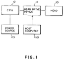
- Fig. 1 shows a control circuit of the printing apparatus.
- a printing head 10 is driven by a head drive device 11.
- the head drive device 11 is controlled by a central processing unit (CPU) 12.
- a power is supplied from a print power source 13 to the printing apparatus.
- An image signal is transmitted from an image signal source (host computer) 101 to the head drive device 11 so that printing is performed by the printing head 10.
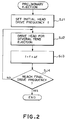
- Fig. 2 is a flowchart for explaining an operation in preliminary ejection.
- a printing head drive frequency f at initiation of preliminary ejection is set.
- the drive frequency f is set at a frequency lower than that in normal printing depending upon a kind of the printing head and printing method.
- step SJ2 the printing head 10 is driven at the set drive frequency f to perform ejection of the liquid in the head 10 for several tens times.
- the drive frequency is set at a frequency (f + ⁇ f) higher than the initial drive frequency f in the extent of ⁇ f.
- step SJ4 judgement is made whether the drive frequency reaches a set final drive frequency. If the final drive frequency is not reached, the process returns to step SJ2 to drive the printing head 10 with the newly set drive frequency f to perform ejection of the liquid in the printing head 10 for several tens times.
- steps SJ2 and SJ3 are repeated until the drive frequency reaches the predetermined final drive frequency set for the preliminary ejection.
- the process to perform preliminary ejection goes end.
- the printing head which normally perform printing with the printing frequency of 5 kHz, is initially driven at the frequency of 500 Hz.
- preliminary ejection is performed for 50 times.
- 50 times preliminary ejection is performed at the frequency of 500 Hz, initially. Then, another 50 times preliminary ejection is performed at the increased frequency of 510 Hz, a further 50 times preliminary ejection is performed at the increased frequency of 520 Hz . Moreover, at the final stage, 50 times preliminary ejection is performed at the frequency of 2000 Hz.
- the drive frequency is increased from the lowest initial value to the predetermined final frequency.
- the drive frequency is also increased according to lowering of the viscosity of the liquid.
- the manner of increasing the drive frequency f may be performed in a manner of geometrical series instead of arithmetical series. For instance, it is possible to perform the preliminary ejection in a manner that the initial ten times of ejection is performed at 2 Hz, next ten times of ejection is performed at 10 Hz, subsequent ten times of ejection is performed at a frequency of 50 Hz, yet subsequent ten times of ejection is performed at 250 Hz.
- Figs. 3 and 4 show the second embodiment according to the present invention.
- the shown embodiment varies the initial value of the drive frequency for preliminary ejection depending upon a resting (non-use) period.
- Fig. 3 shows a control circuit for the second embodiment of the printing apparatus. It should be noted that like reference numerals to the foregoing embodiment represent like elements. Therefore, detailed description for such common elements will be omitted for avoiding redundant discussion which may lead confusion, and whereby to facilitate understanding.
- a counter 14 is connected to CPU 12. To the counter 14, a timer 15 is connected. The timer 15 is electrically connected to a power source 16 which is different from the printing power source 13.
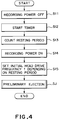
- Fig. 4 is a flowchart showing an operation of preliminary ejection. Hereinafter, discussion will be given for preliminary ejection with reference to the flowchart of Fig. 4.
- step S11 when the printing power source 13 is turned OFF, and at step S2, the timer is driven to initiate operation with the power source 16 other than the printing power source 13.
- step S13 a period is counted up until the printing power source 13 is turned ON by the counter 14.
- the initial head drive frequency f for initiation of preliminary ejection is set.
- step SJ the preliminary ejection is performed with varying the drive frequency f from the low valve to the high value in a like manner set forth in the first embodiment.
- the drive frequency f to be set has to be lower value.
- the initial head drive frequency is set.
- the value may be set practically depending upon kind of the printing head and method of use.
- Figs. 5 and 6 illustrate the third embodiment according to the invention.
- the shown embodiment has the initial drive frequency upon initiation of the preliminary ejection variable depending upon a humidity.
- the shown embodiment of the apparatus is a copying machine to read out an original by means of a scanner 102 and to print the read out image information.
- the apparatus has an ink-jet head for ejecting liquid droplets through a plurality of nozzles.
- Fig. 5 shows a control circuit for the printing apparatus.
- the scanner 102 is connected to the head drive device 11 via an image processing circuit 103.
- the image processing circuit 103 performs image processing on the basis of the image information read out by the scanner 102 so that the printing head 10 may print the image.
- the image processing portion determines the timing and active nozzles relative to scanning.
- a humidity sensor 22 is connected via an analog-to-digital (A/D) converter 21.
- A/D analog-to-digital
- Fig. 6 is a flowchart showing an operation of the preliminary ejection.
- an operation of the preliminary ejection will be discussed according to the flowchart of Fig. 6. It should be noted that, while the shown embodiment measures the resting period of the copying machine by means of the counter 14 and the timer 15 and sets the head drive frequency f upon initiation of the preliminary ejection in substantially the same manner as the foregoing second embodiment, discussion for such process is omitted for avoiding redundant discussion.
- step S21 when the printing power source 13 is turned ON, a humidity data measured by the humidity sensor 22 is input to CPU 12 via the A/D converter 21.
- step S22 judgement is made whether the humidity is lower than a set value or not.
- the head drive frequency f upon initiation of the preliminary ejection is set depending upon the resting period of the printing apparatus, similarly to the foregoing second embodiment.
- the head drive frequency at initiation of the preliminary ejection is set to be further lower frequency at step S23.
- step SJ the preliminary ejection is performed with varying the drive frequency from the lower value to the higher value similarly to the foregoing first embodiment.
- the control set forth above is based on the fact that a lower humidity promotes a higher rate of evaporation of the liquid at the ejection openings so as to increase viscous resistance due to increasing of the viscosity of the liquid, requiring the head drive frequency to be set at further lower value.
- the data read from the humidity sensor 22 is preferably an average value during resting period of the printer. However, the data upon onset of the power supply may also be used.
- Figs. 7 and 8 illustrate the fourth embodiment according to the present invention.
- the initial value of the drive frequency is variable depending upon a temperature.
- Fig. 7 shows a control circuit of the printing apparatus.
- the like reference numerals to the foregoing Fig. 3 represent like elements, and discussion therefor will be omitted.
- the shown embodiment of the printing apparatus is basically the same as that of the foregoing second embodiment.
- a temperature sensor 23 is connected to CPU 12 via an A/D converter 21.
- Fig. 8 is a flowchart showing an operation for the preliminary ejection. It should be noted that while the shown embodiment measures the resting period of the copying machine by means of the counter 14 and the timer 15 and sets the head drive frequency f upon initiation of the preliminary ejection in substantially the same manner as the foregoing second embodiment, discussion for such process is omitted for avoiding redundant discussion.
- a temperature data measured by the temperature sensor 23 is read in the CPU 12 via the A/D converter 21, at step S31. Then, at step S32, judgement is made whether the temperature is lower than a preliminary set value or not.
- the head drive frequency f upon initiation of the preliminary printing is set depending upon the resting period of the printing apparatus, similarly to the foregoing second embodiment.
- the head drive frequency f upon initiation of the preliminary ejection is set to be further lower, at step S33.
- the preliminary ejection is performed with varying the drive frequency from the lower value to the higher value similarly to the foregoing first embodiment.
- the control set forth above is based on the fact that a lower temperature should cause increasing viscous resistance due to increasing of the viscosity of the liquid, requiring the head drive frequency to be set at further lower value.
- the data read from the temperature sensor 23 is preferably an average value during resting period of the printer. However, the data upon onset of the power supply may also be used.
- the present invention achieves distinct effect when applied to a recording head or a recording apparatus which has means for generating thermal energy such as electrothermal transducers or laser light, and which causes changes in ink by the thermal energy so as to eject ink. This is because such a system can achieve a high density and high resolution recording.
- the on-demand type apparatus has electrothermal transducers, each disposed on a sheet or liquid passage that retains liquid (ink), and operates as follows: first, one or more drive signals are applied to the electrothermal transducers to cause thermal energy corresponding to recording information; second, the thermal energy induces sudden temperature rise that exceeds the nucleate boiling so as to cause the film boiling on heating portions of the recording head; and third, bubbles are grown in the liquid (ink) corresponding to the drive signals. By using the growth and collapse of the bubbles, the ink is expelled from at least one of the ink ejection orifices of the head to form one or more ink drops.
- the drive signal in the form of a pulse is preferable because the growth and collapse of the bubbles can be achieved instantaneously and suitably by this form of drive signal.
- a drive signal in the form of a pulse those described in U.S. patent Nos. 4,463,359 and 4,345,262 are preferable.
- the rate of temperature rise of the heating portions described in U.S. patent No. 4,313,124 be adopted to achieve better recording.
- U.S. patent Nos. 4,558,333 and 4,459,600 disclose the following structure of a recording head, which is incorporated to the present invention: this structure includes heating portions disposed on bent portions in addition to a combination of the ejection orifices, liquid passages and the electrothermal transducers disclosed in the above patents. Moreover, the present invention can be applied to structures disclosed in Japanese Patent Application Laying-open Nos. 123670/1984 and 138461/1984 in order to achieve similar effects.
- the former discloses a structure in which a slit common to all the electrothermal transducers is used as ejection orifices of the electrothermal transducers, and the latter discloses a structure in which openings for absorbing pressure waves caused by thermal energy are formed corresponding to the ejection orifices.
- the present invention can be also applied to a so-called full-line type recording head whose length equals the maximum length across a recording medium.
- a recording head may consists of a plurality of recording heads combined together, or one integrally arranged recording head.
- the present invention can be applied to various serial type recording heads: a recording head fixed to the main assembly of a recording apparatus; a conveniently replaceable chip type recording head which, when loaded on the main assembly of a recording apparatus, is electrically connected to the main assembly, and is supplied with ink therefrom; and a cartridge type recording head integrally including an ink reservoir.
- a recovery system or a preliminary auxiliary system for a recording head as a constituent of the recording apparatus because they serve to make the effect of the present invention more reliable.
- the recovery system are a capping means and a cleaning means for the recording head, and a pressure or suction means for the recording head.
- the preliminary auxiliary system are a preliminary heating means utilizing electrothermal transducers or a combination of other heater elements and the electrothermal transducers, and a means for carrying out preliminary ejection of ink independently of the ejection for recording. These systems are effective for reliable recording.
- the number and type of recording heads to be mounted on a recording apparatus can be also changed. For example, only one recording head corresponding to a single color ink, or a plurality of recording heads corresponding to a plurality of inks different in color or concentration can be used.
- the present invention can be effectively applied to an apparatus having at least one of the monochromatic, multi-color and full-color modes.
- the monochromatic mode performs recording by using only one major color such as black.
- the multi-color mode carries out recording by using different color inks, and the full-color mode performs recording by color mixing.
- inks that are liquid when the recording signal is applied can be used: for example, inks can be employed that solidify at a temperature lower than the room temperature and are softened or liquefied in the room temperature. This is because in the ink jet system, the ink is generally temperature adjusted in a range of 30°C - 70°C so that the viscosity of the ink is maintained at such a value that the ink can be ejected reliably.
- the present invention can be applied to such apparatus where the ink is liquefied just before the ejection by the thermal energy as follows so that the ink is expelled from the orifices in the liquid state, and then begins to solidify on hitting the recording medium, thereby preventing the ink evaporation: the ink is transformed from solid to liquid state by positively utilizing the thermal energy which would otherwise cause the temperature rise; or the ink, which is dry when left in air, is liquefied in response to the thermal energy of the recording signal.
- the ink may be retained in recesses or through holes formed in a porous sheet as liquid or solid substances so that the ink faces the electrothermal transducers as described in Japanese Patent Application Laying-open Nos. 56847/1979 or 71260/1985.
- the present invention is most effective when it uses the film boiling phenomenon to expel the ink.
- the ink jet recording apparatus of the present invention can be employed not only as an image output terminal of an information processing device such as a computer, but also as an output device of a copying machine including a reader, and as an output device of a facsimile apparatus having a transmission and receiving function.
Landscapes
- Ink Jet (AREA)
- Particle Formation And Scattering Control In Inkjet Printers (AREA)
Applications Claiming Priority (3)
| Application Number | Priority Date | Filing Date | Title |
|---|---|---|---|
| JP08887894A JP3332569B2 (ja) | 1994-04-26 | 1994-04-26 | 液体噴射プリント装置およびプリント方法 |
| JP8887894 | 1994-04-26 | ||
| JP88878/94 | 1994-04-26 |
Publications (3)
| Publication Number | Publication Date |
|---|---|
| EP0679517A2 true EP0679517A2 (de) | 1995-11-02 |
| EP0679517A3 EP0679517A3 (de) | 1996-05-15 |
| EP0679517B1 EP0679517B1 (de) | 2001-03-28 |
Family
ID=13955267
Family Applications (1)
| Application Number | Title | Priority Date | Filing Date |
|---|---|---|---|
| EP95302773A Expired - Lifetime EP0679517B1 (de) | 1994-04-26 | 1995-04-25 | Druckvorrichtung mit Flüssigkeitsausstoss |
Country Status (5)
| Country | Link |
|---|---|
| US (1) | US6033050A (de) |
| EP (1) | EP0679517B1 (de) |
| JP (1) | JP3332569B2 (de) |
| DE (1) | DE69520461T2 (de) |
| ES (1) | ES2155112T3 (de) |
Cited By (1)
| Publication number | Priority date | Publication date | Assignee | Title |
|---|---|---|---|---|
| CN105246696B (zh) * | 2013-07-25 | 2016-11-16 | 马姆杰特科技有限公司 | 喷墨打印及保持喷嘴水合作用的方法 |
Families Citing this family (23)
| Publication number | Priority date | Publication date | Assignee | Title |
|---|---|---|---|---|
| US6209999B1 (en) * | 1998-12-23 | 2001-04-03 | Eastman Kodak Company | Printing apparatus with humidity controlled receiver tray |
| JP3412569B2 (ja) * | 1999-07-14 | 2003-06-03 | 富士ゼロックス株式会社 | インクジェット記録ヘッドの駆動方法及び駆動装置 |
| JP3485082B2 (ja) | 1999-10-12 | 2004-01-13 | セイコーエプソン株式会社 | インクジェット式記録装置及び記録方法並びに記録媒体 |
| JP2002273912A (ja) | 2000-04-18 | 2002-09-25 | Seiko Epson Corp | インクジェット式記録装置 |
| US6746100B2 (en) * | 2000-07-13 | 2004-06-08 | Brother Kogyo Kabushiki Kaisha | Ink jet recording apparatus and maintenance method |
| US6752480B2 (en) * | 2000-08-07 | 2004-06-22 | Canon Kabushiki Kaisha | Integrated-circuit apparatus and ink jet recording apparatus using the same |
| CN1309574C (zh) * | 2002-07-09 | 2007-04-11 | 索尼株式会社 | 成像设备和其控制方法 |
| JP4288908B2 (ja) * | 2002-07-26 | 2009-07-01 | リコープリンティングシステムズ株式会社 | インクジェット記録装置 |
| JP2004148788A (ja) * | 2002-11-01 | 2004-05-27 | Seiko Epson Corp | 液滴吐出装置及び方法、製膜装置及び方法、デバイス製造方法並びに電子機器 |
| US6945625B2 (en) * | 2003-07-09 | 2005-09-20 | Hewlett-Packard Development Company, L.P. | Determining humidity of fluid-ejection mechanism based at least on spitting recovery level of mechanism |
| US20050094167A1 (en) * | 2003-10-31 | 2005-05-05 | Hewlett-Packard Development Company, L.P. | Method and apparatus of operating a printer |
| US7513416B1 (en) * | 2004-07-29 | 2009-04-07 | Diebold Self-Service Systems | Cash dispensing automated banking machine deposit printing system and method |
| US7178897B2 (en) * | 2004-09-15 | 2007-02-20 | Eastman Kodak Company | Method for removing liquid in the gap of a printhead |
| JP5055701B2 (ja) | 2005-02-24 | 2012-10-24 | ブラザー工業株式会社 | インクジェットヘッドのフラッシング方法 |
| JP2007137023A (ja) * | 2005-11-22 | 2007-06-07 | Fujifilm Corp | 液体吐出装置および液体攪拌方法 |
| JP4944631B2 (ja) * | 2007-02-02 | 2012-06-06 | キヤノン株式会社 | インクジェット記録装置および回復処理方法 |
| JP2009072921A (ja) * | 2007-09-18 | 2009-04-09 | Kyocera Mita Corp | 画像形成装置 |
| JP5451103B2 (ja) | 2008-03-25 | 2014-03-26 | キヤノン株式会社 | インクジェット記録装置および記録ヘッドの回復処理方法 |
| JP5691155B2 (ja) * | 2009-11-10 | 2015-04-01 | ソニー株式会社 | 立体造形物の造形方法及び造形装置 |
| JP5780009B2 (ja) | 2011-06-17 | 2015-09-16 | 株式会社リコー | 液体吐出ヘッドの制御方法及び液体吐出装置 |
| JP5805018B2 (ja) * | 2011-06-30 | 2015-11-04 | 京セラドキュメントソリューションズ株式会社 | 画像形成装置 |
| US8721036B2 (en) * | 2011-10-19 | 2014-05-13 | Eastman Kodak Company | Geographically based humidity adjustment of printhead maintenance |
| CN118650996B (zh) * | 2024-05-30 | 2025-10-03 | 西安理工大学 | 一种基于热电耦合的电流体喷印方法及系统 |
Family Cites Families (26)
| Publication number | Priority date | Publication date | Assignee | Title |
|---|---|---|---|---|
| JPS5448551A (en) * | 1977-09-26 | 1979-04-17 | Ricoh Co Ltd | Ink jet driving circuit |
| CA1127227A (en) * | 1977-10-03 | 1982-07-06 | Ichiro Endo | Liquid jet recording process and apparatus therefor |
| JPS5936879B2 (ja) * | 1977-10-14 | 1984-09-06 | キヤノン株式会社 | 熱転写記録用媒体 |
| US4330787A (en) * | 1978-10-31 | 1982-05-18 | Canon Kabushiki Kaisha | Liquid jet recording device |
| US4345262A (en) * | 1979-02-19 | 1982-08-17 | Canon Kabushiki Kaisha | Ink jet recording method |
| US4463359A (en) * | 1979-04-02 | 1984-07-31 | Canon Kabushiki Kaisha | Droplet generating method and apparatus thereof |
| US4313124A (en) * | 1979-05-18 | 1982-01-26 | Canon Kabushiki Kaisha | Liquid jet recording process and liquid jet recording head |
| JPS572765A (en) * | 1980-06-09 | 1982-01-08 | Seiko Epson Corp | Ink jet recorder |
| US4558333A (en) * | 1981-07-09 | 1985-12-10 | Canon Kabushiki Kaisha | Liquid jet recording head |
| DE3247540A1 (de) * | 1981-12-26 | 1983-07-07 | Konishiroku Photo Industry Co., Ltd., Tokyo | Tintenstrahlschreiber |
| US4558332A (en) * | 1982-04-02 | 1985-12-10 | Canon Kabushiki Kaisha | Ink jet printer |
| JPS59123670A (ja) * | 1982-12-28 | 1984-07-17 | Canon Inc | インクジエツトヘツド |
| JPS59138461A (ja) * | 1983-01-28 | 1984-08-08 | Canon Inc | 液体噴射記録装置 |
| JPS6071260A (ja) * | 1983-09-28 | 1985-04-23 | Erumu:Kk | 記録装置 |
| JPS60101054A (ja) * | 1983-11-08 | 1985-06-05 | Canon Inc | 液体噴射装置 |
| US5339098A (en) * | 1984-02-21 | 1994-08-16 | Canon Kabushiki Kaisha | Liquid discharge recording apparatus having apparatus for effecting preparatory emission |
| JPS61146548A (ja) * | 1984-12-21 | 1986-07-04 | Canon Inc | 液体噴射記録装置 |
| JPS62116153A (ja) * | 1985-11-15 | 1987-05-27 | Canon Inc | 記録装置 |
| US4727378A (en) * | 1986-07-11 | 1988-02-23 | Tektronix, Inc. | Method and apparatus for purging an ink jet head |
| US4926196A (en) * | 1986-12-25 | 1990-05-15 | Canon Kabushiki Kaisha | Ink jet printer |
| JPS63260450A (ja) * | 1987-04-17 | 1988-10-27 | Canon Inc | インクジエツト記録装置の目詰り防止方法 |
| JP2720060B2 (ja) * | 1989-01-31 | 1998-02-25 | キヤノン株式会社 | 回復方法 |
| ES2053215T3 (es) * | 1990-02-13 | 1994-07-16 | Canon Kk | Aparato de impresion por chorros de tinta. |
| DE69219180T2 (de) * | 1991-02-12 | 1997-10-02 | Canon Kk | Tintenstrahlaufzeichnungssystem und Verfahren |
| EP0559122B1 (de) * | 1992-03-02 | 1997-06-11 | Seiko Epson Corporation | Farbstrahldrucker, damit ausgerüstetes elektronisches Gerät und Betriebsverfahren dafür |
| JP3099549B2 (ja) * | 1992-09-18 | 2000-10-16 | 富士ゼロックス株式会社 | インクジェット記録装置におけるヘッド予備駆動方法 |
-
1994
- 1994-04-26 JP JP08887894A patent/JP3332569B2/ja not_active Expired - Fee Related
-
1995
- 1995-04-21 US US08/426,197 patent/US6033050A/en not_active Expired - Lifetime
- 1995-04-25 EP EP95302773A patent/EP0679517B1/de not_active Expired - Lifetime
- 1995-04-25 ES ES95302773T patent/ES2155112T3/es not_active Expired - Lifetime
- 1995-04-25 DE DE69520461T patent/DE69520461T2/de not_active Expired - Lifetime
Cited By (2)
| Publication number | Priority date | Publication date | Assignee | Title |
|---|---|---|---|---|
| CN105246696B (zh) * | 2013-07-25 | 2016-11-16 | 马姆杰特科技有限公司 | 喷墨打印及保持喷嘴水合作用的方法 |
| TWI626168B (zh) * | 2013-07-25 | 2018-06-11 | 滿捷特科技公司 | 噴墨列印及保持噴嘴水合作用的方法 |
Also Published As
| Publication number | Publication date |
|---|---|
| JP3332569B2 (ja) | 2002-10-07 |
| DE69520461D1 (de) | 2001-05-03 |
| ES2155112T3 (es) | 2001-05-01 |
| US6033050A (en) | 2000-03-07 |
| DE69520461T2 (de) | 2001-08-23 |
| JPH07290720A (ja) | 1995-11-07 |
| EP0679517A3 (de) | 1996-05-15 |
| EP0679517B1 (de) | 2001-03-28 |
Similar Documents
| Publication | Publication Date | Title |
|---|---|---|
| US6033050A (en) | Liquid ejection printing apparatus with varying frequency preliminary ejection | |
| US6109724A (en) | Ink jet recording apparatus | |
| EP0469619B1 (de) | Wischvorrichtung und Verfahren an einem Aufzeichnungskopf eines Tintenaufzeichnungsgerätes | |
| JPH0519468B2 (de) | ||
| US6820958B2 (en) | Method for controlling the drive energy of an ink jet print apparatus and the ink jet print apparatus | |
| US6193351B1 (en) | System to perform ink jet printing head recovery | |
| US6227646B1 (en) | Ink jet recording apparatus | |
| US6447096B1 (en) | Ink jet recording apparatus and recovery method therefor | |
| US5483266A (en) | Ink jet recording apparatus with two storage modes | |
| US20090115810A1 (en) | Recording apparatus and recovery control method | |
| JP3015188B2 (ja) | インクジェット記録装置 | |
| JPH09201967A (ja) | インクジェット記録方法及びインクジェット記録装置 | |
| JPH09207358A (ja) | インクジェット記録方法およびその装置 | |
| JP2557875B2 (ja) | 液体噴射記録装置 | |
| JP2728460B2 (ja) | インクジェットプリンタ | |
| JPH04247962A (ja) | インクジェット記録装置 | |
| JP2004090264A (ja) | インクジェット記録装置及びその制御方法、プログラム | |
| JPH06328730A (ja) | インクジェットプリンタ | |
| JPH06238914A (ja) | インクジェット記録装置の吸引動作制御方法およびインクジェット記録装置 | |
| JP2757224B2 (ja) | インクジェット記録装置 | |
| US6126262A (en) | Ink-jet printing apparatus and ink-jet printing method | |
| JP3162794B2 (ja) | インクジェット記録装置および回復方法 | |
| JP3124022B2 (ja) | インクジェット記録装置および不吐出検知方法 | |
| JP2804581B2 (ja) | インクジェット記録装置の操作方法 | |
| JPH11334109A (ja) | インクジェット記録装置 |
Legal Events
| Date | Code | Title | Description |
|---|---|---|---|
| PUAI | Public reference made under article 153(3) epc to a published international application that has entered the european phase |
Free format text: ORIGINAL CODE: 0009012 |
|
| AK | Designated contracting states |
Kind code of ref document: A2 Designated state(s): CH DE ES FR GB IT LI NL |
|
| PUAL | Search report despatched |
Free format text: ORIGINAL CODE: 0009013 |
|
| AK | Designated contracting states |
Kind code of ref document: A3 Designated state(s): CH DE ES FR GB IT LI NL |
|
| 17P | Request for examination filed |
Effective date: 19960925 |
|
| 17Q | First examination report despatched |
Effective date: 19971119 |
|
| GRAG | Despatch of communication of intention to grant |
Free format text: ORIGINAL CODE: EPIDOS AGRA |
|
| GRAG | Despatch of communication of intention to grant |
Free format text: ORIGINAL CODE: EPIDOS AGRA |
|
| GRAG | Despatch of communication of intention to grant |
Free format text: ORIGINAL CODE: EPIDOS AGRA |
|
| GRAH | Despatch of communication of intention to grant a patent |
Free format text: ORIGINAL CODE: EPIDOS IGRA |
|
| GRAH | Despatch of communication of intention to grant a patent |
Free format text: ORIGINAL CODE: EPIDOS IGRA |
|
| GRAA | (expected) grant |
Free format text: ORIGINAL CODE: 0009210 |
|
| AK | Designated contracting states |
Kind code of ref document: B1 Designated state(s): CH DE ES FR GB IT LI NL |
|
| PG25 | Lapsed in a contracting state [announced via postgrant information from national office to epo] |
Ref country code: LI Free format text: LAPSE BECAUSE OF FAILURE TO SUBMIT A TRANSLATION OF THE DESCRIPTION OR TO PAY THE FEE WITHIN THE PRESCRIBED TIME-LIMIT Effective date: 20010328 Ref country code: CH Free format text: LAPSE BECAUSE OF FAILURE TO SUBMIT A TRANSLATION OF THE DESCRIPTION OR TO PAY THE FEE WITHIN THE PRESCRIBED TIME-LIMIT Effective date: 20010328 |
|
| REG | Reference to a national code |
Ref country code: CH Ref legal event code: EP |
|
| REG | Reference to a national code |
Ref country code: ES Ref legal event code: FG2A Ref document number: 2155112 Country of ref document: ES Kind code of ref document: T3 |
|
| REF | Corresponds to: |
Ref document number: 69520461 Country of ref document: DE Date of ref document: 20010503 |
|
| ET | Fr: translation filed | ||
| ITF | It: translation for a ep patent filed | ||
| REG | Reference to a national code |
Ref country code: CH Ref legal event code: PL |
|
| REG | Reference to a national code |
Ref country code: GB Ref legal event code: IF02 |
|
| PLBE | No opposition filed within time limit |
Free format text: ORIGINAL CODE: 0009261 |
|
| STAA | Information on the status of an ep patent application or granted ep patent |
Free format text: STATUS: NO OPPOSITION FILED WITHIN TIME LIMIT |
|
| 26N | No opposition filed | ||
| PGFP | Annual fee paid to national office [announced via postgrant information from national office to epo] |
Ref country code: ES Payment date: 20070412 Year of fee payment: 13 |
|
| PGFP | Annual fee paid to national office [announced via postgrant information from national office to epo] |
Ref country code: NL Payment date: 20070417 Year of fee payment: 13 |
|
| NLV4 | Nl: lapsed or anulled due to non-payment of the annual fee |
Effective date: 20081101 |
|
| PG25 | Lapsed in a contracting state [announced via postgrant information from national office to epo] |
Ref country code: NL Free format text: LAPSE BECAUSE OF NON-PAYMENT OF DUE FEES Effective date: 20081101 |
|
| REG | Reference to a national code |
Ref country code: ES Ref legal event code: FD2A Effective date: 20080426 |
|
| PG25 | Lapsed in a contracting state [announced via postgrant information from national office to epo] |
Ref country code: ES Free format text: LAPSE BECAUSE OF NON-PAYMENT OF DUE FEES Effective date: 20080426 |
|
| PGFP | Annual fee paid to national office [announced via postgrant information from national office to epo] |
Ref country code: IT Payment date: 20090415 Year of fee payment: 15 Ref country code: FR Payment date: 20090424 Year of fee payment: 15 |
|
| REG | Reference to a national code |
Ref country code: FR Ref legal event code: ST Effective date: 20101230 |
|
| PG25 | Lapsed in a contracting state [announced via postgrant information from national office to epo] |
Ref country code: FR Free format text: LAPSE BECAUSE OF NON-PAYMENT OF DUE FEES Effective date: 20100430 |
|
| PG25 | Lapsed in a contracting state [announced via postgrant information from national office to epo] |
Ref country code: IT Free format text: LAPSE BECAUSE OF NON-PAYMENT OF DUE FEES Effective date: 20100425 |
|
| PGFP | Annual fee paid to national office [announced via postgrant information from national office to epo] |
Ref country code: GB Payment date: 20130418 Year of fee payment: 19 Ref country code: DE Payment date: 20130430 Year of fee payment: 19 |
|
| REG | Reference to a national code |
Ref country code: DE Ref legal event code: R119 Ref document number: 69520461 Country of ref document: DE |
|
| GBPC | Gb: european patent ceased through non-payment of renewal fee |
Effective date: 20140425 |
|
| REG | Reference to a national code |
Ref country code: DE Ref legal event code: R119 Ref document number: 69520461 Country of ref document: DE Effective date: 20141101 |
|
| PG25 | Lapsed in a contracting state [announced via postgrant information from national office to epo] |
Ref country code: DE Free format text: LAPSE BECAUSE OF NON-PAYMENT OF DUE FEES Effective date: 20141101 Ref country code: GB Free format text: LAPSE BECAUSE OF NON-PAYMENT OF DUE FEES Effective date: 20140425 |