EP0679781B1 - Coffrage de béton, et tirant et raccord pour l'assemblage du coffrage - Google Patents
Coffrage de béton, et tirant et raccord pour l'assemblage du coffrage Download PDFInfo
- Publication number
- EP0679781B1 EP0679781B1 EP95105122A EP95105122A EP0679781B1 EP 0679781 B1 EP0679781 B1 EP 0679781B1 EP 95105122 A EP95105122 A EP 95105122A EP 95105122 A EP95105122 A EP 95105122A EP 0679781 B1 EP0679781 B1 EP 0679781B1
- Authority
- EP
- European Patent Office
- Prior art keywords
- form member
- portions
- pair
- plate portions
- plate portion
- Prior art date
- Legal status (The legal status is an assumption and is not a legal conclusion. Google has not performed a legal analysis and makes no representation as to the accuracy of the status listed.)
- Expired - Lifetime
Links
- 238000000465 moulding Methods 0.000 title claims description 82
- 230000003014 reinforcing effect Effects 0.000 claims description 18
- 229920002430 Fibre-reinforced plastic Polymers 0.000 claims description 9
- 239000011151 fibre-reinforced plastic Substances 0.000 claims description 9
- 238000009415 formwork Methods 0.000 description 31
- 239000002184 metal Substances 0.000 description 22
- 229910052751 metal Inorganic materials 0.000 description 22
- 239000000057 synthetic resin Substances 0.000 description 15
- 229920003002 synthetic resin Polymers 0.000 description 15
- 239000002023 wood Substances 0.000 description 12
- 239000011120 plywood Substances 0.000 description 11
- 239000000463 material Substances 0.000 description 8
- 230000001681 protective effect Effects 0.000 description 6
- 238000004519 manufacturing process Methods 0.000 description 4
- 230000004048 modification Effects 0.000 description 4
- 238000012986 modification Methods 0.000 description 4
- 230000002093 peripheral effect Effects 0.000 description 4
- 239000004033 plastic Substances 0.000 description 4
- 229920003023 plastic Polymers 0.000 description 4
- 229920005989 resin Polymers 0.000 description 4
- 239000011347 resin Substances 0.000 description 4
- 238000010137 moulding (plastic) Methods 0.000 description 3
- 125000006850 spacer group Chemical group 0.000 description 3
- XEEYBQQBJWHFJM-UHFFFAOYSA-N Iron Chemical compound [Fe] XEEYBQQBJWHFJM-UHFFFAOYSA-N 0.000 description 2
- 238000005452 bending Methods 0.000 description 2
- 238000010276 construction Methods 0.000 description 2
- 239000003365 glass fiber Substances 0.000 description 2
- 230000006872 improvement Effects 0.000 description 2
- 238000009413 insulation Methods 0.000 description 2
- 238000000034 method Methods 0.000 description 2
- 230000002787 reinforcement Effects 0.000 description 2
- 229920001187 thermosetting polymer Polymers 0.000 description 2
- XLYOFNOQVPJJNP-UHFFFAOYSA-N water Substances O XLYOFNOQVPJJNP-UHFFFAOYSA-N 0.000 description 2
- 229920000049 Carbon (fiber) Polymers 0.000 description 1
- 238000010521 absorption reaction Methods 0.000 description 1
- 229910052782 aluminium Inorganic materials 0.000 description 1
- XAGFODPZIPBFFR-UHFFFAOYSA-N aluminium Chemical compound [Al] XAGFODPZIPBFFR-UHFFFAOYSA-N 0.000 description 1
- 239000004760 aramid Substances 0.000 description 1
- 229920003235 aromatic polyamide Polymers 0.000 description 1
- 239000004917 carbon fiber Substances 0.000 description 1
- 239000004568 cement Substances 0.000 description 1
- 230000008878 coupling Effects 0.000 description 1
- 238000010168 coupling process Methods 0.000 description 1
- 238000005859 coupling reaction Methods 0.000 description 1
- 230000002950 deficient Effects 0.000 description 1
- 230000006866 deterioration Effects 0.000 description 1
- 238000011161 development Methods 0.000 description 1
- 230000018109 developmental process Effects 0.000 description 1
- 230000007613 environmental effect Effects 0.000 description 1
- 239000000835 fiber Substances 0.000 description 1
- 239000002440 industrial waste Substances 0.000 description 1
- 229910052742 iron Inorganic materials 0.000 description 1
- VNWKTOKETHGBQD-UHFFFAOYSA-N methane Chemical compound C VNWKTOKETHGBQD-UHFFFAOYSA-N 0.000 description 1
- 238000010422 painting Methods 0.000 description 1
- 229920000728 polyester Polymers 0.000 description 1
- 238000003825 pressing Methods 0.000 description 1
- 239000002994 raw material Substances 0.000 description 1
- 239000012783 reinforcing fiber Substances 0.000 description 1
- 230000008439 repair process Effects 0.000 description 1
- 230000004044 response Effects 0.000 description 1
- 239000007787 solid Substances 0.000 description 1
- 229920005992 thermoplastic resin Polymers 0.000 description 1
Images

















Classifications
-
- E—FIXED CONSTRUCTIONS
- E04—BUILDING
- E04G—SCAFFOLDING; FORMS; SHUTTERING; BUILDING IMPLEMENTS OR AIDS, OR THEIR USE; HANDLING BUILDING MATERIALS ON THE SITE; REPAIRING, BREAKING-UP OR OTHER WORK ON EXISTING BUILDINGS
- E04G9/00—Forming or shuttering elements for general use
- E04G9/02—Forming boards or similar elements
-
- E—FIXED CONSTRUCTIONS
- E04—BUILDING
- E04G—SCAFFOLDING; FORMS; SHUTTERING; BUILDING IMPLEMENTS OR AIDS, OR THEIR USE; HANDLING BUILDING MATERIALS ON THE SITE; REPAIRING, BREAKING-UP OR OTHER WORK ON EXISTING BUILDINGS
- E04G17/00—Connecting or other auxiliary members for forms, falsework structures, or shutterings
- E04G17/04—Connecting or fastening means for metallic forming or stiffening elements, e.g. for connecting metallic elements to non-metallic elements
-
- E—FIXED CONSTRUCTIONS
- E04—BUILDING
- E04G—SCAFFOLDING; FORMS; SHUTTERING; BUILDING IMPLEMENTS OR AIDS, OR THEIR USE; HANDLING BUILDING MATERIALS ON THE SITE; REPAIRING, BREAKING-UP OR OTHER WORK ON EXISTING BUILDINGS
- E04G17/00—Connecting or other auxiliary members for forms, falsework structures, or shutterings
- E04G17/04—Connecting or fastening means for metallic forming or stiffening elements, e.g. for connecting metallic elements to non-metallic elements
- E04G17/042—Connecting or fastening means for metallic forming or stiffening elements, e.g. for connecting metallic elements to non-metallic elements being tensioned by threaded elements
-
- E—FIXED CONSTRUCTIONS
- E04—BUILDING
- E04G—SCAFFOLDING; FORMS; SHUTTERING; BUILDING IMPLEMENTS OR AIDS, OR THEIR USE; HANDLING BUILDING MATERIALS ON THE SITE; REPAIRING, BREAKING-UP OR OTHER WORK ON EXISTING BUILDINGS
- E04G17/00—Connecting or other auxiliary members for forms, falsework structures, or shutterings
- E04G17/06—Tying means; Spacers ; Devices for extracting or inserting wall ties
- E04G17/065—Tying means, the tensional elements of which are threaded to enable their fastening or tensioning
- E04G17/0655—Tying means, the tensional elements of which are threaded to enable their fastening or tensioning the element consisting of several parts
Definitions
- the present invention relates to a concrete molding form member for assembling a concrete formwork which is employed for placing concrete or molding a concrete secondary product in construction and civil engineering works.
- a wood form member comprising a plywood board and bridges which are nailed thereto and a metal form member comprising an iron plate or an aluminum plate and metal ribs which are fixed thereto are known as such concrete molding form members.
- a typical example of the conventional wood form member 70 comprises a flat plate 71 of plywood which is fixed to a plurality of reinforcing bridges 72 with nails 73, for example.
- endmost reinforcing bridges 72 of adjacent form members 70 are fastened to each other with nails 73, for coupling/fixing the form members 70 with/to each other.
- Fig. 54B shows an exemplary concrete formwork which is assembled in the aforementioned manner to have a cross concrete molding part 74.
- the flat plates 71 can be formed by plastic plates, for example, in place of the plywood boards.
- the conventional form member space holder is mainly formed by a separator 121, attachments 122 and clamp members 123.
- the separator 121 comprises a bar and a pair of male screws 121a which are provided on both ends thereof.
- Each male screw 121a is fitted with a female screw 122c which is provided on a first end of each attachment 122 as shown in Fig. 56B.
- a male screw 122d which is provided on a second end of the attachment 122 substantially coaxially with the female screw 122c passes through a separator mounting hole 76 which is provided in each form member 70, so that an end of a substantially truncated-conical resin presser part 122a which is engaged with the outer periphery of an attachment body part 122b is in contact with the concrete placing surface of the form member 70.
- a female screw 123a which is provided on a first end of each clamp member 123 is fitted with the male screw 122d of the attachment 122, thereby clamping/fixing the attachment 122 to each form member 70.
- a male screw 123b is provided on a second end of each clamp member 123 as shown in Fig. 56C, so that a support member 124 and a nut 125 which are mounted on this male screw 123b fix thin cylindrical form member support members 126 of a metal for bridging a plurality of transversely arranged form members 70, as shown in Fig. 55.
- Fig. 57A shows a typical example of a conventional metal form member 80 comprising a metal flat plate 81, and side plates 82 and reinforcing plates 83 which are bonded/fixed to the same.
- Fig. 57B shows a concrete formwork having a cross concrete molding part 84, which is assembled by a plurality of such metal form members 80. In this formwork, metal reinforcements 85 are employed in intersections of the cross concrete molding part 84, in addition to the form members 80.
- Japanese Utility Model Laying-Open No. 62-54149 (1987) discloses a conventional synthetic resin form member which is also well known in the art.
- reinforcing projections which are made of plastic are integrally provided on four points of a back surface portion of a plate member having a square front surface.
- the projections are provided with holes for receiving links, while the plate member is also provided with holes for receiving separators in prescribed portions thereof.
- Japanese Patent Laying-Open No. 2-8459 (1990) discloses a concrete placing form member consisting of a press-molded sheet containing 50 to 10 percent by weight of glass fiber mat in 50 to 90 percent by weight of thermosetting resin.
- Japanese Patent Laying-Open No. 5-59811 (1993) discloses a concrete placing form member comprising a face plate and reinforcing ribs which are provided at least along the longitudinal direction of the face plate.
- the face plate is formed by a fiber reinforced plastic member, while a fiber reinforced plastic material forming the ribs (longitudinal ribs) along the longitudinal direction has a bending elastic modulus of at least 10 GPa and longitudinal flexural rigidity of the form member is set to be at least 2.5 x 10 7 kgf•mm 2 per unit width (1 cm) of the form member.
- the wood form member can be recycled merely 3 to 4 times since the plywood board is separated from its end portion upon employment of several times due to absorption of alkaline moisture, requires skillfulness for assembling/execution, is unsuitable for global environmental protection due to consumption of lauan raw material and industrial waste resulting from the spent form member, and cannot be applied to high-quality concrete having a low slump value and high strength since employment of a vibrator is limited due to low strength, although the same is lightweight and has a degree of freedom in execution.
- the concrete as placed loses an ideal water-cement ratio in a surface portion which is in contact with the plywood board, resulting in a rough state of the finished concrete outer surface. Since an erroneous decision may be made on defective hardening of the concrete in this case, prescribed painting is applied to the surface of the plywood board for reducing its water absorptivity. However, such a painted plywood board is high-priced and hence the cost is disadvantageously increased.
- the metal form member can be hardly applied to general construction works since the executable range is limited due to a small degree of freedom in working, although the same has high strength. Further, the metal form member must be miniaturized due to its heavy weight, leading to inferior executability. Further, insufficient management leads to unusability due to rusting and/or deformation, and it is extremely difficult to repair such a rusted/deformed form member.
- the synthetic resin form member can provide an excellent concrete finished surface
- the aforementioned form member described in Japanese Utility Model Laying-Open No. 62-54149 which comprises a plate member and solid prism-shaped projections similarly to the wood form member except that the same are made of synthetic resin, has a heavy weight and can be manufactured only by press molding due to limitation in its shape, with requirement for a high manufacturing cost.
- existent synthetic form members including those described in Japanese Patent Laying-Open Nos. 2-8459 and 5-59811 are not beyond the ranges of the shapes and functions of the wood and metal form members. Namely, the surfaces, the both side ribs and the back surfaces of such form members have only functions for serving as concrete molding surfaces, form member connecting members and reinforcement forming surfaces respectively, and hence only a single function is decided every surface in these existing form members. Thus, a synthetic resin form member can be used only in the same method as those for the remaining existent form members.
- the conventional synthetic resin form member which is manufactured by press molding, is insufficient in strength and high-priced, and hence the same is hardly put into practice under the present circumstances. Further, the conventional synthetic resin form member is inferior in workability for connection and demolition, since such members are connected with each other through nails or bolts and nuts.
- each attachment 122 In the conventional form member space holder described with reference to Figs. 55 to 56C, on the other hand, the resin presser part 122a and the body part 122b of each attachment 122 are positioned on the concrete placing surface of each form member 70, and hence it is necessary to mount the separator 121 and the attachments 122 before fixing the positions of a pair of form members 70. Once the positions of the form members 70 are fixed, the separator 122 and the attachments 122 can be neither mounted nor demounted, leading to inferior workability.
- a concrete molding form member according to the preamble of claim 1 is known.
- the mounting holes are provided on the portions preferably with distances of 5 cm. Therefore it is an object of the present invention to provide a concrete molding form member comprising the respective advantages of the conventional wood, metal and synthetic resin form members and having both functions of concrete molding surfaces and connecting surfaces not only in its surface but in its side-surfaces, its back-surfaces and its upper- and lower-surfaces to be used in a method absolutely different from that for the conventional synthetic resin form member, wherein the form members can be simply connected with each other or a single form member can be simply connected with a form member connector.
- the structure of claim 6 it is possible to prevent misalignment between the pipe-shaped long bar and the concrete molding form member by storing the pipe-shaped long bar which is inserted in the through holes provided in the horizontal end plate portion in the spaces having square horizontal sections enclosed with the front plate portion, the pair of side plate portions, the pair of rear plate portions and the pair of reinforcing thick portions respectively, due to the reinforcing thick portions which are provided on the inner side end portions of the pair of rear plate portions.
- the pipe-shaped long bar which is strongly mounted on the concrete molding form member can serve not only as a connector for connecting a plurality of concrete molding form members along the lonqitudinal direction but a reinforcing member.
- a concrete molding form member 1 according to this embodiment comprises a front plate portion 3, a pair of strip side plate portions 4, and a pair of strip rear plate portions 5.
- Fig. 1 is a perspective view showing the concrete molding form member 1 from behind.
- the front plate portion 3 of the concrete molding form member 1 is formed by a long flat plate having cross-sectional ends 3A, longitudinal ends 3B which are separated from each other by a length of about 10 times that between the cross-sectional ends 3A, a flat surface 3C and a flat back surface 3D.
- the pair of side plate portions 4 are in the form of long strip bodies perpendicularly extending from the cross-directional ends 3A of the front plate portion 3 toward the back surface 3D to be opposite to each other and having flatly formed surfaces 4A.
- the pair of rear plate portions 5 are in the form of long strip bodies perpendicularly inwardly extending from cross-directional forward ends 4B of the side plate portions 4, to face the back surface 3D of the front plate portion 3.
- the rear plate portions have flatly formed surfaces 5A and inwardly projecting forward ends forming reinforcing thick portions 5B.
- a form member body 2 according to this embodiment defined by the front plate portion 3, the pair of side plate portions 4 and the pair of rear plate portions 5 which are integrally formed with each other is integrally molded by a fiber reinforced plastic material through continuous draw molding, and the thicknesses of the front plate portion 3 and the side plate portions 4 are set at about 5 mm respectively, while those of the reinforcing thick portions 5B are set at about 10 mm.
- the reinforcing fiber is preferably prepared from glass fiber, while the same may alternatively be prepared from carbon fiber or Aramid (trade name) fiber.
- the plastic component is preferably prepared from polyester-based thermosetting resin, while the same may alternatively be prepared from thermoplastic resin.
- the front plate portion 3 of the form member body 2 is provided on its cross-sectional center with a plurality of mounting holes 6 at prescribed intervals along the longitudinal direction.
- each of the pair of side plate portions 4 is also provided with a plurality of mounting holes 7 in correspondence to the positions of the mounting holes 6 provided in the front plate poriton 3 respectively, and each of these mounting holes 7 is arranged on a position which is cross-directionally separated from the surface 3C of the front plate portion 3 by a prescribed distance L.
- each of the pair of rear plate portions 5 are provided with a plurality of mounting holes 8 also in correspondence to the positions of the mounting holes 6 provided in the front plate portion 3, and each of these mounting holes 8 is also arranged on a position which is cross-directionally separated from the surface 4A of the side plate portion 4 by the same prescribed distance L.
- Each end plate body 9 is integrally formed by a fiber reinforced plastic member having a substantially U-shaped section which is provided with a flat horizontal end plate portion 10 shielding either longitudinal end of the form member body 2 and a pair of vertical end plate portions 11 and 12 perpendicularly extending from front and rear ends of the horizontal end plate portion 10 respectively.
- the horizontal end plate portion 10 is formed to be engaged with a space having a rectangular plane shape which is enclosed with the front plate portion 3, the pair of side plate portions 4 and the pair of rear plate portions 5.
- the front end surface of the front vertical end plate portion 11 is in contact with and fixed to the back surface 3D of the front plate portion 3, while the rear vertical end plate portion 12 is formed to be engaged between the pair of rear plate portions 5 while facing the vertical end plate portion 11. All of surfaces 10A, 11A and 12A of the horizontal end plate portion 10 and the pair of vertical end plate portions 11 and 12 are flatly formed respectively.
- a mounting hole 13 is provided in the longitudinal center of each horizontal end plate portion 10, and this mounting hole 13 is arranged in a position separated from the surface 3C of the front plate portion 3 along the cross direction of the horizontal end plate portion 10 at a distance which is substantially identical to the distance L between the center of each mounting hole 7 and the surface 3C of the front end portion 3.
- a mounting hole 14 is formed in the longitudinal center of the rear vertical end plate portion 12, and the center of this mounting hole 14 is arranged in a position separated from the surface 10A of the horizontal end plate portion 10 along the cross direction of the vertical end plate portion 12 at a distance which is substantially identical to the distance L.
- end plate bodies 9 provided in the form member 1 Due to the end plate bodies 9 provided in the form member 1 according to this embodiment, it is possible to connect end portions of two form members as described later with reference to Fig. 18, as well as to improve rigidity in the vicinity of the end portions of the form members. If it is not necessary to connect/fix end portions of such form members with/to each other, or no high strength is required in the vicinity of the end portions of the form members, however, it is also possible to employ a form member 101 which is engaged with no end plate bodies 9 on its end portions, as shown in Fig. 29.
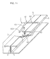
- reinforcing thick portions 5B are provided on the forward ends of the pair of rear plate portions 5 forming the form member body 2 in the concrete molding form member 1 according to this embodiment, these reinforcing thick portions 5B serve as ribs for increasing the strength of the rear plate portions 5 which are pressed/held by a clip on end portions thereof when two form members are connected with/fixed to each other by a specific form member connector such as the clip holding the rear plate portions 5, as described later with reference to Fig. 11. Therefore, when the form members are connected with/fixed to each other not by such a clip-type form member connector but in a manner described later with reference to Figs. 12 to 14, for example, it is not necessary to provide the reinforcing thick portions 5B since no such strength is required for the rear plate portions 5 in this case.
- Figs. 30A to 30C illustrate three types of sectional shapes in the vicinity of longitudinal or transverse end portions of form members.
- Fig. 30A shows a longitudinal or transverse U-shaped end portion of a form member whose inner side is substantially in the form of a cylindrical surface to have thick corner portions.
- reinforcing ribs are provided in the vicinity of longitudinal or transverse end portions of a form member.
- Fig. 30C further, longitudinal or transverse end portions of a form member are in the form of cylinders having rectangular sections. Due to such modifications of the sectional shape, rigidity is reinforced particularly in the vicinity of the end portions of the form members, thereby providing form members capable of forming concrete formworks having high pressure resistance.
- FIGs. 5 and 6 show a connector 21 having a U-shaped section, as a first exemplary connector.
- This connector 21 is provided with a long base plate portion 22 having a cross-directional size 2L which is substantially twice the distance L between each of the mounting holes 7 and the surface 3C, and a pair of connecting plate portions 23, having the same cross-directional size 2L as the base plate portion 22, perpendicularly extending from cross-directional edges of the base plate portion 22 to face each other, while the base plate portion 22 and the connecting portions 23 are integrally formed by a fiber reinforced plastic member.
- surfaces 22A and 23A of the base plate portion 22 and the connecting plate portions 23 are flatly formed while a plurality of mounting holes 24 are provided in the cross-directional center of each connecting plate portion 23 in longitudinal positions corresponding to those of the mounting holes 6 and 7 provided in the form member body 2.
- the distance L between each mounting hole 24 and the surface 22A of the base plate portion 22 is identical to that between each mounting hole 7 or 8 of the form member 1 and the surface 3C or 4A.
- Figs. 7 and 8 show a connector 31 having an L-shaped section, as a second exemplary connector.
- This connector 31 is formed by a pair of connecting plate portions 32 which are integrally molded in an L shape by a fiber reinforced plastic material to have flatly formed surfaces 32A.
- Each connecting plate portion 32 is provided in its cross-sectional center with a plurality of mounting holes 33 in longitudinal positions corresponding to the respective mounting holes 6, 7 and 8 of the form member body 2 at prescribed spaces, and the distance L between each mounting hole 33 and an outer angular corner 32B of the connecting plate portion 32 is set to be identical to that between each mounting hole 7 or 8 of the form member 1 and the surface 3C.
- the mounting holes 6, 7 and 13 are located on concrete molding surfaces, and each of the mounting holes 6, 7 and 13 is closed as shown in Fig. 31E by a synthetic resin plug 61 shown in Figs. 31A to 31D, for preventing leakage of the concrete as placed from the mounting holes 6, 7 and 13.
- Each of the mounting holes 6, 7 and 13 of the form member body 2 can alternatively be closed by a plug 62 shown in Figs. 32A to 32D.
- This plug 62 is provided in the center of its grip portion with a circular opening 62a, so that the same can be readily gripped by the fingers of an operator or with a holder in attachment/detachment to/from each mounting hole 6.
- a portion 62b of the plug 62 to be engaged with the mounting hole 6 is divided into four, so that its outer diameter is widened on the forward end.
- FIG. 32D is a sectional view showing the plug 62 which is engaged with the mounting hole 6 of the form member body 2 through a mounting hole protective cup 63.
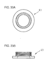
- the mounting hole protective cup 63 which is shaped as shown in Figs. 33A and 33B, is made of a metal such as stainless, for example.
- FIG. 34A An end plate body 9a shown in Figs. 34A and 34B is formed by folding a single plate in a plane shape which is sized to be engaged with the inner side of the form member body 2, so that an upper end surface of the end plate body 9a is bonded/fixed in a state being flush with an end surface of the form member body 2 as shown in Fig. 34B when the end plate body 9a is engaged in the end of the form member body 2 as shown in Fig. 34A.
- an upper plate portion 10b is formed to be larger than that of the end plate body 9a appearing in Figs. 34A and 34B as shown in Fig. 35A, so that the upper plate portion 10b entirely covers the end surface of the form member body 2 in engagement with the end portion thereof, as shown in Fig. 35B.
- the upper plate portion 10b is provided on lower portions of its horizontal sides with a pair of engaging portions 63 which are inserted and engaged in the space enclosed with the front plate portion 3, the side plate portions 4 and the rear plate portions 5 of the form member body 2, so that the outer peripheral side portions of the end plate body 9b and the inner peripheral side portions of the form member body 2 are substantially entirely in contact and engaged with each other, thereby improving the strength at the end poriton of the form member 1.
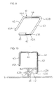
- Figs. 9 to 11 show a form member connecting clip 41, as a first exemplary form member connector.
- This form member connecting clip 41 comprises an insertional shaft portion 42, a first holding portion 43, a grip portion 44 and a second holding portion 45, which are integrally formed by bending an elastic wire.
- the length between a base end 42A and a free forward end 42B is set to be longer than the lateral width of each rear plate portion 5 of the form member body 2.
- a front end 43A of the first holding portion 43 rearwardly extends from the base end 42A of the insertional shaft portion 42 in a perpendicularly bent manner.
- the grip portion 44 is perpendicularly bent at a rear end 43B of the first holding portion 43, to transversely extend similarly to the insertional shaft portion 42.
- the second holding portion 45 is perpendicularly bent at a forward end 44A of the grip portion 44, to be opposed to the first holding portion 43.
- a forward end 45A of the second holding portion 45 is transversely outwardly bent to define a free end.
- a synthetic resin spacer 46 having an outer diameter which is receivable in each of the mounting holes 7 and 13 is engaged with the insertional shaft portion 42.
- the insertional shaft portion 42 is transversely inserted in butted mounting holes 7 (or 13) of the pair of form members 1 which are aligned and brought into contact with each other as shown in Fig. 11, through the spacer 46.
- the grip portion 44 is gripped and rotated either clockwise or anticlockwise about the insertional shaft portion 42, so that a pair of rear plate portions 5 are held between the first and second holding portions 43 and 45.
- the form member connecting clip 41 may be made of synthetic resin, in place of the wire.
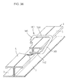
- a form member connecting clip 141 shown in Fig. 36 as the form member connecting member.
- This form member connecting clip 141 has an insertional shaft portion 142, a first holding portion 143, a grip portion 144 and a second holding portion 145 corresponding to the insertional shaft portion 42, the first holding portion 43, the grip portion 44 and the second holding portion 45 of the aforementioned form member connecting clip 41 respectively.
- this form member connecting clip 141 has no portion corresponding to the synthetic resin spacer 46 or the bent forward end 45A of the second holding portion 45 provided in the form member connecting clip 41. It is possible to apply this form member connecting clip 141 to two types of form member connecting portions shown in Figs. 37A and 37B, by properly setting the lengths of the respective portions.
- Fig. 37C shows a plan view showing an exemplary T-shaped concrete molding formwork which is assembled through the same type of form member connecting clips 141 in such two modes.
- the insertional shaft portion 142 or the second holding portion 145 of each form member connecting clip 141 is inserted in each mounting hole of each form member body 2 through a mounting hole protective cup 63 to be temporarily tacked thereto, so that the clip 141 is rotated about the inserted portion in connection/fixation, to be fixed while holding the rear plate portions 5 of the pair of form members 1 as shown in Fig. 36.
- Such a form member connecting clip 41 can be formed by simply folding a single metal bar or the like to be applicable in two different modes, whereby the cost for the connecting member can be reduced.
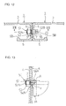
- Figs. 12 to 14 show a form member connecting bolt 51 as a second exemplary form member connecting portion.
- This form member connecting bolt 51 comprises a bolt body 52, a nut 53 and a clamp lever 54.
- the bolt body 52 is provided on its first and second ends with a male screw portion 52A and an expanding slot 52B respectively.
- the nut 53 is fitted with the male screw portion 52A and rotated about the axis of the bolt body 52, to be reciprocative along the axial direction.
- the clamp lever 54 has a bent surface 54A provided on its longitudinal forward end and a clamp surface 54B defined by its side surface.
- This clamp lever 54 is coupled through a pin 55 in a state engaged in the expanding slot 52B of the insertional shaft portion 52, to be rotatable about the pin 55.
- the distance r between the pin 55 and the clamp surface 54B is set to be slightly longer than the distance R between the same and the longitudinal forward end of the clamp lever 54 so that the pin 55 is eccentric, whereby clamping force acts upon rotation of
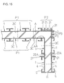
- FIG. 15 shows an exemplary structure of a formwork for molding a concrete foundation A. Referring to Fig. 15, illustration of the form member connecting clips 41 and the form member connecting bolts 51 is omitted.
- a plurality of form members 1 are connected with each other so that cross sections thereof extend linearly thereby forming a pair of flat panels P1, and a first angular corner panel P2 is formed by connecting three U-shaped connectors 21 with each other on one side surface of an L-shaped angular corner, while a second angular corner panel P3 is formed by connecting two U-shaped connectors 21 with each other.
- the angular corner panels P2 and P3 are connected with each other by an L-shaped connector 31.
- L-shaped connector 31 As shown in Fig. 15, it is possible to set the flat panels P1 at desired lengths by interposing the U-shaped connectors 21 between the form members 1 which are so arranged that cross sections thereof extend linearly. An end portion is closed with a plywood board B which is fixed to side plate portions 4 of the endmost form members 1. Referring to Fig. 15, one-dot chain lines show positions for mounting separators.
- surfaces 3C and 4A of the front plate portions 3 and the side plate portions 4 serve as concrete molding surfaces in the form members 1, while surfaces 22A of base plate portions 22 serve as concrete molding surfaces and surfaces 23A of connecting plate portions 23 serve as connecting surfaces in the U-shaped connectors 21 respectively.
- Fig. 16 shows such an exemplary structure that an opposite pair of form members 1 are connected with/fixed to each other by an additional form member 1 which is perpendicularly combined therewith.
- the additional form member 1 is perpendicularly built into a clearance between the opposite form members 1 through the mounting holes 6 which are adapted to receive separators in general.
- surfaces 3C of the opposite front plate portions 3 serve both as concrete molding surfaces and connecting surfaces.
- Fig. 17 shows another exemplary structure which is different from the above.
- rear plate portions 5 of an additional form member 1 are connected to side plate portions 4 of an opposite pair of form members 1 while clearances between the rear plate portions 5 and the back surface 3D of the front plate portion 3 of the additional form member 1 are closed with L-shaped connectors 31, thereby forming flat surfaces which are flush with opposite front plate portions 3.
- the back surface 3D of the front plate portion 3 which is positioned on the end portion and first surfaces 32A of the L-shaped connectors 31 serve as concrete molding surfaces.
- a plurality of form members 1 may be longitudinally connected with each other in transversely directed states as shown in Fig. 18.
- surfaces 10A of end plate portions 10 of end plate bodies 9 also serve as concrete molding surfaces.
- Fig. 19 shows an exemplary structure of concrete molding form panels formed by vertically assembling form members 1 with each other so that cross sections thereof extend linearly.
- surfaces 4A of side plate portions 4 serve as connecting surfaces.
- Fig. 20 shows an exemplary structure of form panels which are formed by assembling form members 1 in the form of a cross, so that surfaces 4A and 5A of side plate portions 4 and rear plate portions 5 serve as connecting portions at angular corners respectively.
- FIG. 22 shows an exemplary structure of form panels which are formed by assembling form members 1 in a T shape, so that surfaces 4A and 5A of side plate portions 4 and rear plate portions 5 serve as connecting portions at angular corners respectively.
- triple U-shaped connectors 21 are employed to adjust the dimensions of the form panels.
- Fig. 22 shows an exemplary structure of form panels which are formed by assembling transversely directed form members 1 with each other so that surfaces 4A and 10A of side plate portions 4 and end plate portions 10 serve as connecting surfaces.
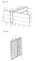
- Fig. 23 shows an exemplary structure of form panels which are formed by transversely connecting form members 1 with upper ends of vertically directed form members 1 so that surfaces 4A of side plate portions 4 as well as surfaces 4A and 10A of the strip side plate portions 4 and end plate portions 10 serve as connecting surfaces respectively.
- Fig. 24 shows an exemplary structure of form panels which are formed by transversely connecting form members 1 with vertically connected form members 1 so that surfaces 4A and 10A of side plate portions 4 and end plate portions 10 serve as connecting surfaces respectively.
- FIG. 25 shows an exemplary structure of form panels which are formed by assembling form members 1 in the form of a hollow prism for molding a pillar, so that four panels which are formed by triple form members 1 are connected with each other by four L-shaped connectors 31.
- surfaces 4A and 32A of side plate portions 4 and connecting plate portions 32 serve as connecting surfaces.
- the form member 1 according to this embodiment is not only capable of forming the aforementioned various structures but has excellent strength as compared with the conventional wood, synthetic resin and metal form members, and can be reduced to about 1/3 in weight in the same shape. Consequently, it is possible to lengthen the form member 1 to the maximum size which can be handled by a single operator, thereby increasing the area of each form member. Therefore, a single operator can assemble a single stage form panel with no footstool, as shown in Fig. 26. Due to the high strength, further, it is not necessary to support a plurality of form members 1 which are connected in parallel with each other by square bar-shaped support members for transversely bridging and fixedly supporting the same, but extremely excellent workability can be attained.
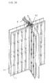
- Fig. 38 shows a state of placing concrete 92 from a concrete supply pipe 91 into a concrete formwork having a cross concrete molding portion which is formed by connecting/fixing a plurality of form members 1 according to this embodiment with/to each other through form member connectors 41.
- the form member 101 provided with no end plate bodies 9 may alternatively be employed as shown in Fig. 29, when the form member 101 is used in a vertically directed state. In this case, it is possible to partially cut the form member 101 at need.
- the dimensions of the form members 1 and 101 according to the aforementioned embodiments are not univocally decided but the respective dimensions such as the lengths and/or the widths can be properly set such that a plurality of form members having different dimensions may be previously prepared so that various form members are employed at need.
- a pair of form members 1 are opposed to each other so that positions of corresponding separator mounting holes 6 thereof are aligned with each other while holding a prescribed space therebetween for forming a desired concrete placing portion, and a separator 131 is inserted in each separator mounting hole 6 of one form member 1 so that a pair of attachments 132 and clamp members 133 are mounted on both ends of the separator 131 in each separator mounting hole 6, thereby fixing the form members 1 to each other.
- transversely adjacent form members 1 are connected with/fixed to each other by form member connecting clips 141.
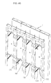
- Fig. 40 shows such a state that two sets of four form members 1, i.e., eight form members 1 in total, are assembled with each other by the form member space holders according to this embodiment through the concrete placing portion.
- Fig. 41 is a plan sectional view showing a pair of opposite form members 1 which are fixed to each other by the form member space holder according to this embodiment.
- the separator 131, each attachment 132 and each clamp member 133 forming the space holder according to this embodiment are coupled with each other in employment, as shown in Fig. 42A.
- the attachment 132 is shaped as shown in Figs. 42B to 42D, so that a male screw 131a provided on a first end of the separator 131 is fitted with a female screw portion 132a which is provided on a first end thereof.
- a male screw 133a which is provided on a first end of the clamp member 133 is fitted with a female screw portion 132b provided on a second end of the attachment 132.
- a male screw 133b is provided on a second end of the clamp member 133 to be fitted with the nut 134, which is employed for fixing a bar-shaped form member support member for bridging a plurality of form members as arranged, along the direction of arrangement.
- a support member 124 is mounted on each clamp member 133, to be employed for supporting a thin cylindrical form member support member 126 which is fixed to bridge the arranged form members 1, similarly to the support member 124 of the conventional form member space holder shown in Fig. 55.
- the separator 131 is inserted in the separator mounting hole 6 provided in one form member 1 while fixing relative positions of the opposite pair of form members 1, for example, so that small diameter portions of the pair of attachments 132 are fitted with the male screws 131a which are provided on both ends of the separator 131 while being engaged with the separator mounting holes 6 through mounting hole protective cups 63. Thereafter plate type check bars 135 are mounted on end portions, being close to the attachments 132, of the clamp members 133 which are fitted with second ends of the attachments 132 respectively.
- the plate-type check bars 135 have recesses for mounting on the clamp members 133 in centers of elastic rectangular flat plate members, so that portions close to both ends thereof are in contact with the pairs of rear plate portions 5 of the form members 1 and slightly elastically deformed in such mounting states for pressing the attachments 132 by elastic force thereby fixing the attachments 132 to the form members 1.
- the separator 131 may be inserted in a sleeve 136 before assembling the form member space holder, so that the separator 131 is removed to leave the sleeve 136 after concrete placing.
- the sleeve 136 is made of a material having low heat conductivity similarly to concrete.
- the metal separator 131 is left in the concrete as placed. If the concrete forms a wall having temperature difference between the interior and the exterior thereof, heat conduction is caused between the interior and the exterior of the wall through the separator 131, to exert a bad influence on heat insulation of the concrete wall.
- FIG. 43 to 46 Another embodiment of the inventive form member space holder is now described with reference to Figs. 43 to 46.
- the basic structure of this embodiment is in common with that of the aforementioned embodiment described with reference to Figs. 39 to 42, and hence the following description is made only on a point of this embodiment which is different from the aforementioned embodiment.
- a T-shaped clamp member 151 consisting of a plastic molding is employed in place of the metal clamp member 133 employed in the embodiment shown in Figs. 39 to 42. Also in this embodiment, structures similar to those shown in Figs. 39 and 40 are applied as to a separator 131, check bars 135, a form member connecting clip and the like.
- the clamp member 151 As shown in Figs. 45A and 45B in enlarged manners, the clamp member 151 according to this embodiment is provided with a form member support member presser portion 151a and a female screw 151b on first and second ends thereof respectively. As shown in Fig. 45C, the female screw 151b is fitted with a male screw 131a of the separator 131. As to the form member support member presser portion 151a, on the other hand, metal thin cylindrical form member support members 126 are pressed against form members 1 so that outer peripheries thereof are engaged along inner curved surfaces of such form member support member presser portions 151a, as shown in Fig. 46.
- the form member space holder of this embodiment it is possible to hold a space between opposite form members at a prescribed distance by a simple operation of fitting the male screw 131a provided on the end of each separator 131 with the female screw 151b of each T-shaped clamp member 151, with no requirement for members corresponding to the attachments 132 and the nuts 134 employed in the aforementioned embodiment shown in Figs. 39 to 42.
- a vertical pair of thin cylindrical form member support members 126 are supported by the form member support member presser portion 151a of the clamp member 151, whereby the clamp member 151 can serve both as the clamp member 133 and the support member 124 provided in the aforementioned embodiment.
- a plastic molding can be applied as the clamp member 151 according to this embodiment, whereby the production cost can be extremely reduced.
- FIG. 47 Still another embodiment of the form member space holder is now described with reference to Figs. 47 to 49.
- the form member space holder according to this embodiment is different from the aforementioned embodiment shown in Figs. 43 to 46 in a point that an L-shaped clamp member 152 is employed in place of the T-shaped clamp member 151 of the aforementioned embodiment.
- a separator 131, check bars 135, a form member connecting clip and the like are similar to those of the embodiment shown in Fig. 44.
- Fig. 48A is a front elevational view of the clamp member 152 according to this embodiment.
- a plan view of the clamp member 152 is identical to Fig. 45A for the aforementioned embodiment.
- the form member space holder it is possible to hold a space between opposite form members at a prescribed distance while supporting thin cylindrical form member support members 126 as shown in Fig. 49, by a simple operation of fitting a male screw 131a of each separator 131 with a female screw 152b of each clamp member 152 as shown in Fig. 48B.
- the clamp member 152 according to this embodiment can also be formed by a plastic molding, thereby reducing the production cost in addition to improvement in working efficiency.
- the form member according to the present invention is also effectively applicable to execution of a concrete formwork for forming the so-called slab, which is a concrete member for forming the floor of a building, as described below.
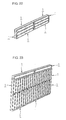
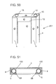
- a pair of through holes 15 having the same inner diameters are provided in the vicinity of horizontal side ends of an end plate body 10 of a form member 201, as shown in Fig. 50, for example. Due to the pair of through holes 15, it is possible to longitudinally connect two form members 201 with each other by longitudinally serially arranging the form members 201 so that the through holes 15 thereof are opposed to each other and inserting pipe-shaped long bars 150, which are sized to be engaged with the through holes 15, in the opposite through holes 15.
- Fig. 51 is an enlarged sectional view taken along the line X - X in Fig. 52B.
- the form members 201 which are longitudinally connected with each other can be arbitrarily contracted along arrow A shown in Fig. 52A, due to sliding movement between the connecting pipe-shaped long bars 150 and the respective form members 201.
- the pipe-shaped long bars 150 are stored in respective spaces which are enclosed with front plate portions 3, pairs of side plate portions 4, pairs of rear plate portions 5 and pairs of reinforcing thick portions 5B of the form members 201 and engaged to be substantially in contact with the inner peripheral surfaces of the spaces, whereby no transverse misalignment is caused between the form members 201 and the pipe-shaped long bars 150.
- the pipe-shaped log bars 150 themselves serve as reinforcing members, whereby the form members 201 as connected can attain sufficient strength against transverse loads.
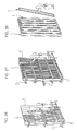
- Fig. 53 shows a state of building a concrete formwork for forming a slab with the form members 201 which are longitudinally connected with each other.
- horizontally arranged form members 201 which are now being assembled with each other are adapted to form a bottom surface of the concrete formwork for forming a slab.
- Plywood boards or the like are engaged in the portions exposing pipe-shaped long bars 150 for connecting the form members 201 with each other, so that overall form member surfaces for forming the floor of the slab are laid with no clearances.
- the existent metal form member requires large-sized support means due to its heavy weight, while it is difficult to build a concrete formwork for forming a slab with existent plastic form members, due to a high cost.
- a concrete formwork for forming a slab is inevitably formed by plywood form members.
- the form members according to the embodiment of the present invention shown in Figs. 50 to 52 remarkably improve applicability to a slab due to the specific advantages such as lightweightness, high strength and retractability.
- the advantages of the form member according to this embodiment are applicable not only to a concrete formwork for forming a slab but to a concrete formwork for forming a wall, as a matter of course.
Landscapes
- Engineering & Computer Science (AREA)
- Architecture (AREA)
- Mechanical Engineering (AREA)
- Civil Engineering (AREA)
- Structural Engineering (AREA)
- Forms Removed On Construction Sites Or Auxiliary Members Thereof (AREA)
- Moulds, Cores, Or Mandrels (AREA)
Claims (6)
- Elément formant coffrage pour mouler du béton comprenant :une partie en forme de bande formant plaque avant (3) étant plate au moins sur sa surface ;ceux parties horizontales en forme de bande formant plaque latérale (4, 4) s'étendant depuis les deux extrémités latérales de ladite partie formant plaque avant (3) en direction d'une surface arrière de celle-ci perpendiculairement à ladite partie formant plaque avant (3) ; etdeux parties horizontales en forme de bande formant plaque arrière (5, 5) s'étendant en direction de l'intérieur depuis les extrémités arrière desdites parties formant plaque latérale (4, 4) perpendiculairement auxdites parties formant plaque latérale (4, 4), devant être opposées à ladite surface arrière de ladite partie formant plaque avant (3) ;chacune de ladite partie formant plaque avant (3), desdites parties formant plaque latérale (4, 4) et desdites parties formant plaque arrière (5, 5) étant pourvue de plusieurs trous de montage (6, 7, 8) ; caractérisé en ce que les trous de montage (6, 7, 8) sont aux mêmes positions par rapport au sens longitudinal à intervalles déterminés dans le sens longitudinal, eten ce que les distances entre le centre desdits trous de montage (7) prévus dans lesdites parties formant plaque latérale (4, 4) et dans ladite partie formant plaque avant (3) sont déterminées de manière à être sensiblement écales à celles entre le centre desdits trous de montage (8) prévus dans lesdites parties formant plaque arrière (5, 5) et lesdites parties formant plaque latérale (4, 4) qui sont adjacentes auxdites parties formant plaque arrière (5, 5).
- Elément de coffrage pour mouler du béton selon la revendication 1, dans lequel, ladite partie formant plaque avant (3), lesdites deux parties formant plaque latérale (4, 4) et lesdites deux parties formant plaque arrière (5, 5) définissent un corps d'élément formant coffrage,ledit élément formant coffrage pour mouler du béton comprenant en outre un corps formant une plaque d'extrémité (9) étant pourvu :d'une partie formant plaque d'extrémité horizontale (10) qui est disposée sur au moins l'une des extrémités supérieure et inférieure dudit corps d'élément formant coffrage de manière à recouvrir une extrémité supérieure ou inférieure d'un espace ayant une partie horizontale rectangulaire qui est enfermée par ladite partie formant plaque avant (3), lesdites deux parties formant plaque latérale (4, 4) et lesdites deux parties formant plaque arrière (5, 5), etd'une partie formant plaque d'extrémité verticale (12) s'étendant depuis une extrémité arrière de ladite partie formant plaque d'extrémité horizontale (10) perpendiculairement à ladite partie formant plaque d'extrémité horizontale (10) de manière à être en contact avec ies surfaces intérieures desdites deux parties formant plaque d'extrémité (5, 5),lesdites parties formant plaques d'extrémité horizontales et verticales (10, 12) étant pourvues sur le centre horizontal de chacune respectivement de trous de montage (13, 14),les distances entre le centre desdits trous de montage (13, 14) desdites parties formant plaques d'extrémité horizontales et verticales (10, 12) et ladite surface de ladite partie formant plaque avant (3) et une surface de la partie formant plaque d'extrémité horizontale (10) étant déterminées de manière à être sensiblement égales à celles entre ledit centre desdits trous de montage (7) prévus dans lesdites parties formants plaque latérale (4, 4) et ladite surface de ladite partie formant plaque avant (3).
- Elément de coffrage pour mouler du béton selon les revendications 1 ou 2, dans lequel ladite partie formant plaque avant (3), lesdites deux parties formant plaque latérale (4, 4) et lesdites deux parties formant plaque arrière (5, 5) consistent en un élément de matière plastique renforcée par fibres.
- Elément de coffrage pour mouler du béton selon les revendications 2 ou 3, dans lequel ledit corps de l'élément de coffrage (2) et ledit corps formant plaque d'extrémité (9) consistent respectivement en éléments de matière plastique renforcée par fibres.
- Elément de coffrage pour mouler du béton selon les revendications 2 à 4, dans lequel deux trous traversants (15) ayant le même diamètre intérieur sont prévus à proximité des parties formant côté horizontal de ladite partie formant plaque d'extrémité horizontale (10) qui forment ledit corps formant plaque d'extrémité (9).
- Elément de coffrage pour mouler du béton selon la revendication 5, dans lequel lesdites deux parties formant plaque arrière (5, 5) dudit corps de l'élément de coffrage (2) sont pourvues sur le côté intérieur des parties formant extrémité de celles-ci de parties épaisses de renfort (5B, 5B) qui s'étendent depuis le côté intérieur desdites parties formant extrémité en direction de ladite partie formant plaque avant (3) perpendiculairement auxdites deux parties formant plaque arrière (5, 5),chacun desdits deux trous traversants respectifs (15) étant prévu dans ladite partie formant plaque d'extrémité horizontale (10) dudit corps formant plaque d'extrémité (9) étant disposés en des positions situées dans l'alignement vertical de deux espaces horizontaux ayant des parties horizontales carrées enfermés respectivement par ladite partie formant plaque avant (3), lesdites deux parties formant plaque latérale (4, 4), lesdites deux parties formant plaque arrière (5, 5) et lesdites deux parties épaisses de renfort (5B, 5B).
Applications Claiming Priority (6)
| Application Number | Priority Date | Filing Date | Title |
|---|---|---|---|
| JP11396294 | 1994-04-28 | ||
| JP11396294 | 1994-04-28 | ||
| JP113962/94 | 1994-04-28 | ||
| JP242874/94 | 1994-10-06 | ||
| JP6242874A JP2717514B2 (ja) | 1994-04-28 | 1994-10-06 | コンクリート成形用型枠材 |
| JP24287494 | 1994-10-06 |
Publications (3)
| Publication Number | Publication Date |
|---|---|
| EP0679781A2 EP0679781A2 (fr) | 1995-11-02 |
| EP0679781A3 EP0679781A3 (fr) | 1996-02-21 |
| EP0679781B1 true EP0679781B1 (fr) | 1999-11-17 |
Family
ID=26452822
Family Applications (1)
| Application Number | Title | Priority Date | Filing Date |
|---|---|---|---|
| EP95105122A Expired - Lifetime EP0679781B1 (fr) | 1994-04-28 | 1995-04-05 | Coffrage de béton, et tirant et raccord pour l'assemblage du coffrage |
Country Status (7)
| Country | Link |
|---|---|
| US (1) | US5632923A (fr) |
| EP (1) | EP0679781B1 (fr) |
| JP (1) | JP2717514B2 (fr) |
| CN (1) | CN1057812C (fr) |
| CA (1) | CA2147023C (fr) |
| DE (1) | DE69513321T2 (fr) |
| TW (1) | TW301689B (fr) |
Families Citing this family (33)
| Publication number | Priority date | Publication date | Assignee | Title |
|---|---|---|---|---|
| US6117521A (en) * | 1995-01-25 | 2000-09-12 | Teijin-Metton Kabushiki Kaisha | Concrete formwork |
| JP3078766B2 (ja) * | 1997-07-09 | 2000-08-21 | 義行 早川 | 断熱コンクリート壁成形方法 |
| US5833873A (en) * | 1997-08-21 | 1998-11-10 | Structural Countours, Inc. | Aluminum concrete forming system |
| JPH11256817A (ja) * | 1998-03-16 | 1999-09-21 | Long Home Kk | コンクリート成形用型枠材 |
| BE1012698A3 (nl) * | 1999-06-02 | 2001-02-06 | Cometal Nv | Bekistingselement en bekisting hiermee uitgevoerd. |
| US6676102B1 (en) * | 2000-02-18 | 2004-01-13 | Symons Corporation | Adjustable modular form system and method for rectilinear concrete column form |
| FR2810061A1 (fr) * | 2000-06-09 | 2001-12-14 | Metallerie Du Beton Gidebe S A | Moule metallique pour la construction de batiments a usage prive ou public anti-sismique |
| RU2211901C2 (ru) * | 2001-07-30 | 2003-09-10 | Луцкий Дмитрий Олегович | Универсальный комплект опалубки |
| AU2002335482A1 (en) * | 2002-10-01 | 2004-04-23 | Toru Yoshimatsu | Components of concrete form, production method therefor, concrete form, and concrete placing method |
| US20080111049A1 (en) * | 2003-09-19 | 2008-05-15 | Huber Donald G | Concrete Forming Apparatus for Foundation Pier Blocks and a Method for Constructing Pier Blocks |
| ITRM20030508A1 (it) * | 2003-10-31 | 2005-05-01 | Enrico Fioroni | Sistema di serraggio di pannelli per casseforme. |
| DE102004014944A1 (de) * | 2004-03-26 | 2005-10-13 | Doka Industrie Gmbh | Schalungsbauteil |
| US20060011801A1 (en) * | 2004-07-16 | 2006-01-19 | Michael Benic | Retaining system |
| MY168491A (en) * | 2006-11-15 | 2018-11-09 | Wendy Yong | A system of formwork and connecting means |
| ES2329747B1 (es) * | 2008-01-11 | 2010-06-01 | Sistemas Tecnicos De Encofrados S.A. | Panel de encofrado para pilares y muros. |
| US20090301030A1 (en) * | 2008-06-10 | 2009-12-10 | Tamio Nojima | Wall construction system |
| CO6290099A1 (es) * | 2009-12-10 | 2011-06-20 | Pimiento Efrain Rojas | Sistema de encofrado metalico graduable para estructuras en concreto |
| WO2011084274A1 (fr) | 2009-12-21 | 2011-07-14 | Reynolds Consumer Products, Inc. | Structure de pavement composite |
| DE102010001693A1 (de) * | 2010-02-09 | 2011-08-11 | Peri GmbH, 89264 | Rahmentafelschalungselement |
| CN102268921A (zh) * | 2010-04-23 | 2011-12-07 | 吴方伯 | 一种建筑用梁模板 |
| IT1408522B1 (it) * | 2010-10-20 | 2014-06-27 | Martigli | Cassero a perdere assemblabile con cui comporre casseforme modulari per la costruzione di fondazioni in calcestruzzo |
| JP2011132803A (ja) * | 2011-02-04 | 2011-07-07 | Hoshin Co Ltd | 構築用型枠支持支柱 |
| CN102561679B (zh) * | 2012-03-12 | 2015-05-20 | 浙江汉德邦建材有限公司 | 装配式楼承板、固定件及现浇混凝土楼板的施工方法 |
| DE102012217823A1 (de) * | 2012-09-28 | 2014-04-03 | Harsco Infrastructure Services Gmbh | Wandschalung mit Abdichtungssystem |
| WO2014058419A1 (fr) * | 2012-10-10 | 2014-04-17 | Pedro Del Pino | Unités de maintien et moules intégrés |
| CN103343618B (zh) * | 2013-07-25 | 2016-02-24 | 上海建工四建集团有限公司 | 用于双层钢筋混凝土板墙空腔施工的大钢模板 |
| CN103485535B (zh) * | 2013-10-16 | 2015-08-12 | 李德福 | 一种快速拆装塑料建筑模板的牵拉杆装置 |
| WO2015159863A1 (fr) * | 2014-04-14 | 2015-10-22 | 三菱レイヨン株式会社 | Élément structural long et complexe d'éléments structuraux utilisant celui-ci |
| FR3060622B1 (fr) * | 2016-12-21 | 2020-10-02 | Electricite De France | Coffrage permanent a beton et procede de fabrication d'une structure composite metal-beton utilisant un tel coffrage |
| CN107386628A (zh) * | 2017-08-22 | 2017-11-24 | 南方风机股份有限公司 | 一种新式铝合金模板结构 |
| CN113152899B (zh) * | 2021-04-07 | 2023-03-28 | 新疆蓬隆建设工程有限公司 | 一种自动架设溜槽的管道基座浇筑小车 |
| CN113550574A (zh) * | 2021-07-27 | 2021-10-26 | 晟通科技集团有限公司 | 阴角模板及模板框架 |
| CN114033096B (zh) * | 2021-12-13 | 2022-11-25 | 中国铁路武汉局集团有限公司武汉房建生活段 | 一种装配式混凝土板结构及施工方法 |
Family Cites Families (16)
| Publication number | Priority date | Publication date | Assignee | Title |
|---|---|---|---|---|
| DE727391C (de) * | 1931-09-12 | 1942-11-02 | Thea Luchterhand Geb Rott | Schalung aus eisernen, mit U-foermigen Umboerdelungen versehenen Blechtafeln |
| FR1011770A (fr) * | 1949-03-16 | 1952-06-26 | élément pour la fabrication de coffrages métalliques | |
| FR987069A (fr) * | 1949-03-28 | 1951-08-08 | Strasbourg Forges | Coffrage métallique pour travaux légers en superstructure ou souterrains |
| US3291436A (en) * | 1963-06-27 | 1966-12-13 | Edward P Berghammer | Panel form for concrete construction |
| US3246871A (en) * | 1964-04-06 | 1966-04-19 | Symons Mfg Co | Rivetless concrete wall form panel with plywood facing and metal studding |
| US3399859A (en) * | 1966-12-23 | 1968-09-03 | Symons Mfg Co | Rivetless concrete wall form panel with plywood facing and metal studding |
| AR203593A1 (es) * | 1975-04-17 | 1975-09-22 | Marseillan J | Nuevo encofrado para muros y lo similar |
| FR2544356B1 (fr) * | 1983-04-18 | 1987-07-17 | Pujol Barcons Salvador | Ensemble de construction pour la coulee de structures rigides monolithiques et procede de construction de telles structures |
| US5205942A (en) * | 1987-02-12 | 1993-04-27 | Fitzgerald Leonard R | Lipped channel formwork |
| US4915345A (en) * | 1987-12-18 | 1990-04-10 | Symons Corporation | Concrete forming system for curved walls |
| EP0332961B1 (fr) * | 1988-03-14 | 1993-01-07 | Eaton Corporation | Transmission auxiliaire en tant qu'unité d'entrée |
| GR1000304B (el) * | 1988-03-28 | 1992-05-12 | Pafili Diethnis Viom Kai Empor | Εξαρτηματα συναρμολογησεως επιφανειων δια την κατασκευη καλουπιων εκχυσεως σκυροδεματος. |
| US5137251A (en) * | 1989-08-30 | 1992-08-11 | Economy Forms Corporation | Pour window for a concrete form |
| DE4009425A1 (de) * | 1990-03-23 | 1991-09-26 | Hollmann Niels | Betonierungs-schaltafel |
| JPH0559811A (ja) * | 1991-08-27 | 1993-03-09 | Toyobo Co Ltd | コンクリート打設用型枠 |
| JP2765431B2 (ja) * | 1993-04-28 | 1998-06-18 | 住友化学工業株式会社 | 透視性を有するコンクリート型枠 |
-
1994
- 1994-10-06 JP JP6242874A patent/JP2717514B2/ja not_active Expired - Lifetime
- 1994-11-03 TW TW083110152A patent/TW301689B/zh active
-
1995
- 1995-04-05 DE DE69513321T patent/DE69513321T2/de not_active Expired - Fee Related
- 1995-04-05 EP EP95105122A patent/EP0679781B1/fr not_active Expired - Lifetime
- 1995-04-11 US US08/420,167 patent/US5632923A/en not_active Expired - Lifetime
- 1995-04-13 CA CA002147023A patent/CA2147023C/fr not_active Expired - Fee Related
- 1995-04-28 CN CN95104198A patent/CN1057812C/zh not_active Expired - Fee Related
Also Published As
| Publication number | Publication date |
|---|---|
| JP2717514B2 (ja) | 1998-02-18 |
| EP0679781A3 (fr) | 1996-02-21 |
| DE69513321D1 (de) | 1999-12-23 |
| JPH0813792A (ja) | 1996-01-16 |
| CA2147023A1 (fr) | 1995-10-29 |
| US5632923A (en) | 1997-05-27 |
| CA2147023C (fr) | 1999-08-17 |
| EP0679781A2 (fr) | 1995-11-02 |
| CN1057812C (zh) | 2000-10-25 |
| TW301689B (fr) | 1997-04-01 |
| CN1113286A (zh) | 1995-12-13 |
| DE69513321T2 (de) | 2000-04-13 |
Similar Documents
| Publication | Publication Date | Title |
|---|---|---|
| US5632923A (en) | Concrete molding form member | |
| CA2264512C (fr) | Piece de coffrage a beton | |
| JPH07279411A (ja) | コンクリート用型枠 | |
| EP0758043A1 (fr) | Dispositif anti-déformation pour coffrages de béton et méthode d'assemblage de coffrages de béton comportant et dispositif | |
| JPH06502700A (ja) | 縁部で突出する、偏平材料より成る縁部ウエブを備えた型枠パネル | |
| EP1349766B1 (fr) | Agencement de liaison des longerons du chassis d'un vehicule | |
| KR200303750Y1 (ko) | 건축물 축조용 거푸집 보강대의 클램프 | |
| CA2206191C (fr) | Panneau de coffrage et glissiere de securite | |
| JPH075153Y2 (ja) | 型枠コーナ用連結具 | |
| JPH0718854A (ja) | Frp製型枠 | |
| JP2778533B2 (ja) | 型枠構造体の間隔設定具及びそれを用いた型枠構造体施工法 | |
| CN1090707C (zh) | 具有一增强件紧固部的系固件 | |
| JPH071445Y2 (ja) | 型枠補強材の締付け金具 | |
| JPS6316766Y2 (fr) | ||
| JPH0240192Y2 (fr) | ||
| HK1023170B (en) | Concrete form member | |
| JPH0239038Y2 (fr) | ||
| JP2514769B2 (ja) | 梁受け方法及び梁受け金具 | |
| JPH07217203A (ja) | 型枠組立具および型枠組立方法 | |
| KR20040048805A (ko) | 건축재료용 연결부재 체결구조 | |
| JP2000054481A (ja) | ベランダ壁取付け構造 | |
| JPH0882093A (ja) | コンクリート型枠 | |
| JP2002129704A (ja) | 根太補強金物 | |
| JPH09137604A (ja) | バタ角受け具 | |
| JPH06185142A (ja) | 壁パネルの接続構造 |
Legal Events
| Date | Code | Title | Description |
|---|---|---|---|
| PUAI | Public reference made under article 153(3) epc to a published international application that has entered the european phase |
Free format text: ORIGINAL CODE: 0009012 |
|
| AK | Designated contracting states |
Kind code of ref document: A2 Designated state(s): DE FR GB |
|
| PUAL | Search report despatched |
Free format text: ORIGINAL CODE: 0009013 |
|
| AK | Designated contracting states |
Kind code of ref document: A3 Designated state(s): DE FR GB |
|
| 17P | Request for examination filed |
Effective date: 19960726 |
|
| 17Q | First examination report despatched |
Effective date: 19980713 |
|
| GRAG | Despatch of communication of intention to grant |
Free format text: ORIGINAL CODE: EPIDOS AGRA |
|
| GRAG | Despatch of communication of intention to grant |
Free format text: ORIGINAL CODE: EPIDOS AGRA |
|
| GRAH | Despatch of communication of intention to grant a patent |
Free format text: ORIGINAL CODE: EPIDOS IGRA |
|
| GRAH | Despatch of communication of intention to grant a patent |
Free format text: ORIGINAL CODE: EPIDOS IGRA |
|
| GRAA | (expected) grant |
Free format text: ORIGINAL CODE: 0009210 |
|
| AK | Designated contracting states |
Kind code of ref document: B1 Designated state(s): DE FR GB |
|
| ET | Fr: translation filed | ||
| REF | Corresponds to: |
Ref document number: 69513321 Country of ref document: DE Date of ref document: 19991223 |
|
| PLBE | No opposition filed within time limit |
Free format text: ORIGINAL CODE: 0009261 |
|
| STAA | Information on the status of an ep patent application or granted ep patent |
Free format text: STATUS: NO OPPOSITION FILED WITHIN TIME LIMIT |
|
| 26N | No opposition filed | ||
| REG | Reference to a national code |
Ref country code: GB Ref legal event code: IF02 |
|
| PGFP | Annual fee paid to national office [announced via postgrant information from national office to epo] |
Ref country code: DE Payment date: 20080430 Year of fee payment: 14 |
|
| PGFP | Annual fee paid to national office [announced via postgrant information from national office to epo] |
Ref country code: FR Payment date: 20080418 Year of fee payment: 14 |
|
| PGFP | Annual fee paid to national office [announced via postgrant information from national office to epo] |
Ref country code: GB Payment date: 20080423 Year of fee payment: 14 |
|
| GBPC | Gb: european patent ceased through non-payment of renewal fee |
Effective date: 20090405 |
|
| REG | Reference to a national code |
Ref country code: FR Ref legal event code: ST Effective date: 20091231 |
|
| PG25 | Lapsed in a contracting state [announced via postgrant information from national office to epo] |
Ref country code: DE Free format text: LAPSE BECAUSE OF NON-PAYMENT OF DUE FEES Effective date: 20091103 |
|
| PG25 | Lapsed in a contracting state [announced via postgrant information from national office to epo] |
Ref country code: GB Free format text: LAPSE BECAUSE OF NON-PAYMENT OF DUE FEES Effective date: 20090405 Ref country code: FR Free format text: LAPSE BECAUSE OF NON-PAYMENT OF DUE FEES Effective date: 20091222 |