EP0680132B1 - Vorrichtung zum Erzeugen einer Reaktionskraft - Google Patents
Vorrichtung zum Erzeugen einer Reaktionskraft Download PDFInfo
- Publication number
- EP0680132B1 EP0680132B1 EP95105923A EP95105923A EP0680132B1 EP 0680132 B1 EP0680132 B1 EP 0680132B1 EP 95105923 A EP95105923 A EP 95105923A EP 95105923 A EP95105923 A EP 95105923A EP 0680132 B1 EP0680132 B1 EP 0680132B1
- Authority
- EP
- European Patent Office
- Prior art keywords
- rotor
- reaction force
- alternating current
- coils
- permanent magnets
- Prior art date
- Legal status (The legal status is an assumption and is not a legal conclusion. Google has not performed a legal analysis and makes no representation as to the accuracy of the status listed.)
- Expired - Lifetime
Links
- 230000002093 peripheral effect Effects 0.000 claims description 19
- 238000000034 method Methods 0.000 claims description 11
- 230000007246 mechanism Effects 0.000 claims description 2
- 230000008859 change Effects 0.000 description 11
- 238000010276 construction Methods 0.000 description 5
- 239000011295 pitch Substances 0.000 description 4
- 230000004907 flux Effects 0.000 description 3
- 238000004804 winding Methods 0.000 description 3
- XEEYBQQBJWHFJM-UHFFFAOYSA-N Iron Chemical compound [Fe] XEEYBQQBJWHFJM-UHFFFAOYSA-N 0.000 description 2
- 206010044565 Tremor Diseases 0.000 description 2
- 230000001133 acceleration Effects 0.000 description 2
- 230000004075 alteration Effects 0.000 description 2
- 238000009499 grossing Methods 0.000 description 2
- 230000004048 modification Effects 0.000 description 2
- 238000012986 modification Methods 0.000 description 2
- 230000004044 response Effects 0.000 description 2
- 230000001360 synchronised effect Effects 0.000 description 2
- 230000008901 benefit Effects 0.000 description 1
- 230000007423 decrease Effects 0.000 description 1
- 230000003111 delayed effect Effects 0.000 description 1
- 238000010586 diagram Methods 0.000 description 1
- 230000000694 effects Effects 0.000 description 1
- 229910052742 iron Inorganic materials 0.000 description 1
- 210000003205 muscle Anatomy 0.000 description 1
- 230000010355 oscillation Effects 0.000 description 1
- 230000000149 penetrating effect Effects 0.000 description 1
- 238000004088 simulation Methods 0.000 description 1
Images


Classifications
-
- G—PHYSICS
- G09—EDUCATION; CRYPTOGRAPHY; DISPLAY; ADVERTISING; SEALS
- G09B—EDUCATIONAL OR DEMONSTRATION APPLIANCES; APPLIANCES FOR TEACHING, OR COMMUNICATING WITH, THE BLIND, DEAF OR MUTE; MODELS; PLANETARIA; GLOBES; MAPS; DIAGRAMS
- G09B9/00—Simulators for teaching or training purposes
- G09B9/02—Simulators for teaching or training purposes for teaching control of vehicles or other craft
- G09B9/04—Simulators for teaching or training purposes for teaching control of vehicles or other craft for teaching control of land vehicles
-
- A—HUMAN NECESSITIES
- A63—SPORTS; GAMES; AMUSEMENTS
- A63F—CARD, BOARD, OR ROULETTE GAMES; INDOOR GAMES USING SMALL MOVING PLAYING BODIES; VIDEO GAMES; GAMES NOT OTHERWISE PROVIDED FOR
- A63F13/00—Video games, i.e. games using an electronically generated display having two or more dimensions
- A63F13/25—Output arrangements for video game devices
- A63F13/28—Output arrangements for video game devices responding to control signals received from the game device for affecting ambient conditions, e.g. for vibrating players' seats, activating scent dispensers or affecting temperature or light
- A63F13/285—Generating tactile feedback signals via the game input device, e.g. force feedback
-
- A—HUMAN NECESSITIES
- A63—SPORTS; GAMES; AMUSEMENTS
- A63F—CARD, BOARD, OR ROULETTE GAMES; INDOOR GAMES USING SMALL MOVING PLAYING BODIES; VIDEO GAMES; GAMES NOT OTHERWISE PROVIDED FOR
- A63F13/00—Video games, i.e. games using an electronically generated display having two or more dimensions
- A63F13/20—Input arrangements for video game devices
- A63F13/24—Constructional details thereof, e.g. game controllers with detachable joystick handles
- A63F13/245—Constructional details thereof, e.g. game controllers with detachable joystick handles specially adapted to a particular type of game, e.g. steering wheels
-
- A—HUMAN NECESSITIES
- A63—SPORTS; GAMES; AMUSEMENTS
- A63F—CARD, BOARD, OR ROULETTE GAMES; INDOOR GAMES USING SMALL MOVING PLAYING BODIES; VIDEO GAMES; GAMES NOT OTHERWISE PROVIDED FOR
- A63F13/00—Video games, i.e. games using an electronically generated display having two or more dimensions
- A63F13/80—Special adaptations for executing a specific game genre or game mode
- A63F13/803—Driving vehicles or craft, e.g. cars, airplanes, ships, robots or tanks
-
- H—ELECTRICITY
- H02—GENERATION; CONVERSION OR DISTRIBUTION OF ELECTRIC POWER
- H02K—DYNAMO-ELECTRIC MACHINES
- H02K26/00—Machines adapted to function as torque motors, i.e. to exert a torque when stalled
-
- H—ELECTRICITY
- H02—GENERATION; CONVERSION OR DISTRIBUTION OF ELECTRIC POWER
- H02K—DYNAMO-ELECTRIC MACHINES
- H02K33/00—Motors with reciprocating, oscillating or vibrating magnet, armature or coil system
- H02K33/12—Motors with reciprocating, oscillating or vibrating magnet, armature or coil system with armatures moving in alternate directions by alternate energisation of two coil systems
-
- A—HUMAN NECESSITIES
- A63—SPORTS; GAMES; AMUSEMENTS
- A63F—CARD, BOARD, OR ROULETTE GAMES; INDOOR GAMES USING SMALL MOVING PLAYING BODIES; VIDEO GAMES; GAMES NOT OTHERWISE PROVIDED FOR
- A63F2300/00—Features of games using an electronically generated display having two or more dimensions, e.g. on a television screen, showing representations related to the game
- A63F2300/10—Features of games using an electronically generated display having two or more dimensions, e.g. on a television screen, showing representations related to the game characterized by input arrangements for converting player-generated signals into game device control signals
- A63F2300/1037—Features of games using an electronically generated display having two or more dimensions, e.g. on a television screen, showing representations related to the game characterized by input arrangements for converting player-generated signals into game device control signals being specially adapted for converting control signals received from the game device into a haptic signal, e.g. using force feedback
-
- A—HUMAN NECESSITIES
- A63—SPORTS; GAMES; AMUSEMENTS
- A63F—CARD, BOARD, OR ROULETTE GAMES; INDOOR GAMES USING SMALL MOVING PLAYING BODIES; VIDEO GAMES; GAMES NOT OTHERWISE PROVIDED FOR
- A63F2300/00—Features of games using an electronically generated display having two or more dimensions, e.g. on a television screen, showing representations related to the game
- A63F2300/10—Features of games using an electronically generated display having two or more dimensions, e.g. on a television screen, showing representations related to the game characterized by input arrangements for converting player-generated signals into game device control signals
- A63F2300/1062—Features of games using an electronically generated display having two or more dimensions, e.g. on a television screen, showing representations related to the game characterized by input arrangements for converting player-generated signals into game device control signals being specially adapted to a type of game, e.g. steering wheel
-
- A—HUMAN NECESSITIES
- A63—SPORTS; GAMES; AMUSEMENTS
- A63F—CARD, BOARD, OR ROULETTE GAMES; INDOOR GAMES USING SMALL MOVING PLAYING BODIES; VIDEO GAMES; GAMES NOT OTHERWISE PROVIDED FOR
- A63F2300/00—Features of games using an electronically generated display having two or more dimensions, e.g. on a television screen, showing representations related to the game
- A63F2300/80—Features of games using an electronically generated display having two or more dimensions, e.g. on a television screen, showing representations related to the game specially adapted for executing a specific type of game
- A63F2300/8017—Driving on land or water; Flying
-
- H—ELECTRICITY
- H02—GENERATION; CONVERSION OR DISTRIBUTION OF ELECTRIC POWER
- H02K—DYNAMO-ELECTRIC MACHINES
- H02K21/00—Synchronous motors having permanent magnets; Synchronous generators having permanent magnets
- H02K21/12—Synchronous motors having permanent magnets; Synchronous generators having permanent magnets with stationary armatures and rotating magnets
- H02K21/14—Synchronous motors having permanent magnets; Synchronous generators having permanent magnets with stationary armatures and rotating magnets with magnets rotating within the armatures
Definitions
- This invention relates to a reaction force generating apparatus for providing a reaction force for a rotationally either manually or mechanically operated member and to a method of generating a reaction force for a rotationally operated member.
- reaction force generating apparatuses have been conventionally incorporated into driving game machines that simulate driving. Specifically, in such driving game machines, the vehicle on the screen turns right or left when a player rotates a steering wheel of the game machine. The steering wheel is provided with a reaction force, so that the player feels as if he or she is actually driving a vehicle.
- Arm gears of training machines for building muscles also incorporate springs to create a reaction force when the arm gears are rotated.
- DE-A-3 221 048 discloses a synchronous electric motor for driving a valve or flap via an output shaft, the driven member being restored to its start position by means of a spring.
- the motor can also lock the driven member in any position by exerting a force opposing that of the spring.
- the actuator according to this prior art generates a reaction force against the force of the spring and there is no suggestion to identify the torque exerted by spring with that exerted by a human operator on the steering wheel of a driving game machine.
- US-A-4 447 793 shows that, with a motor of the type used in the present application, a rotationally operated valve-type member can be switched between two discrete positions by alternately changing the direct current supplied to only two of the three windings, the current in the third winding remains constant, while EP-A-0 375 050 shows that three equilibrium positions can be achieved by varying the direct current in all three windings. Nevertheless none of these documents discloses or suggests repeating this current change at a predetermined frequency over a predetermined time period. Therefore it is not possible to simulate the vibration of the steering wheel of a vehicle travelling over rough ground.
- the obtained reaction force merely operates to reinstate the steering wheel of driving game machine or the arm gear of training machine to its original position.
- an urging force provided by means of a spring(s) deteriorates over an extended period of use.
- an object of the present invention is to provide a durable and simple-structured reaction force generating apparatus and a respective method for generating a reaction force for rotationally operated members.
- each coil of the alternating motor is fed, not with an alternating current, but with a direct current to generate a magnetic field oriented in one direction at the stator.
- An electromagnetic attraction force is created between the magnetic field and the permanent magnets, which maintains the rotor, and thereby the operated member fixed thereto, in a predetermined angular position.
- the stop position of the rotor can be changed by varying the value of the direct current to be supplied to the multi-phase coils, and thereby changing the direction of the magnetic field generated by the stator. Since commutator, brush and other mechanical sliding members that are present on direct current motors can be dispensed with when using an alternating motor, the apparatus of the present invention is superior in durability than prior art devices containing direct current motor.
- the preferred frequency of oscillation between the alternating currents would be, for instance, 5 cycles per second.
- the operated member can be rotationally vibrated during the predetermined time period by alternately varying the direct current that is supplied to the coils at the predetermined frequency.
- the present invention further proposes a reaction force generating apparatus as described above, in which the pole teeth provided in the stator are formed at an angle in relation to the rotational axis of the rotor.
- the peripheral edges of the permanent magnets are not spatially parallel to the pole teeth which, when excited by the energized coils of the stator, define the magnetic poles of the magnetic field.
- the apparatus would thus fail to provide an adequate reaction force when the operated member is only slightly rotated and the permanent magnet is displaced to the position indicated by phantom lines 16', while a constant value of direct current is being supplied to the coils by the actuating means, or when there is only a slight change in the direct current supplied by the actuating means to the coils.
- the afore-described reaction force generating apparatus is operative even if the permanent magnets to be mounted on the rotor have a relatively large surface, equal to that of the magnet in Fig. 10A, area. This is due to the angled position of the peripheral edges of the permanent magnets in relation to the pole teeth, as shown in Fig. 10B. With this construction, any minor change in the relative position between the magnetic pole of the stator and the permanent magnets, i.e. from 16a to 16', results in an increase of the surface area on the permanent magnets that faces the magnetic pole generated by the stator.
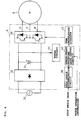
- the reaction force generating apparatus 2 directly generates a reaction force for a steering wheel 4, which is rotationally operated by a player to steer a virtual vehicle to the right or left, on the screen of a driving game machine (not shown) which provides simulation of driving.
- the reaction force generating apparatus 2 includes a three-phase alternating motor 6 and a controller 8 which serves as actuating means for controlling the alternating motor 6.
- the alternating motor 6 is fixed to the lower part of the screen of the game machine, with its rotational axle 6a projecting toward a driver's seat where a player is to be seated.
- a steering wheel 4 is fixedly mounted onto an end of the rotational axle 6a.
- the controller 8 supplies power to the alternating motor 6, in a manner which will be described later, in response to an instruction from a controlling computer controlling the driving game machine.
- the alternating motor 6 includes: a case 10 rotatably supporting the rotational axle 6a; a lid 11 for closing an open side 10a of the case 10 with the rotational axle 6a penetrating therethrough; stator 12 which is fixed to the inner peripheral surface of the case 10; rotor 14 which is made of iron and fixed to the outer periphery of the rotational axle 6a; and a pair of permanent magnets 16 and 18, not shown, which are mounted to the outer peripheral surface of the rotor 14.
- the rotational axle 6a is rotatably supported via a bearing 19a and a bearing 19b which are provided in the case 10 and the lid 11, respectively.
- an internally threaded projection 20 Adjacent to an end of the rotational axle 6a that is opposite to the steering wheel 4, that is to say an end that projects out of the lid 11, an internally threaded projection 20 is formed.
- the projection 20 is rotatable with the rotational axle 6a and has a first threaded member 22 screwed thereinto.
- a circular cap 24 is screwed into an end surface of the lid 11 so as to cover the projection 20 and the first threaded member 22.
- a second threaded member 26 is screwed through the cap 24 at a position thereon, such that when the rotational axle 6a is rotated, the first threaded member 22 and the second threaded member 26 abut against one another.
- a rotatable range of the rotational axle 6a is thus defined.
- the stator 12 has a known three-phase V-phase coil 28 wound therein, which is made of a U-phase, and W-phase.
- the pole teeth K on one half of the periphery of the stator 12 are magnetized to the north polarity, while the pole teeth K on the other half of the periphery are magnetized to the south polarity.
- Magnetic flux is thus generated between the two halves of the stator 12 and is alternated by 120 degrees when a voltage is applied alternately to the coils of each phase, such that the coils of the same phase are energized in turn.
- a first permanent magnet 16 and a second permanent magnet 18 are mounted onto the outer peripheral surface of the rotor 14, facing in opposite directions.
- the first permanent magnet 16 has its south polarity at the side facing the pole teeth K and its north polarity at the side facing the rotor 14.
- the second permanent magnet 18 has its north polarity at the side facing the pole teeth K and its south polarity at the side facing the rotor 14, respectively. It is noted in Figs. 3 and 8 that, the legend "S" on the first permanent magnet 16 and the legend "N” on the second permanent magnet 18, respectively, represent the polarity of the magnets 16 and 18 at the side facing the pole teeth K.
- alternating currents U, V and W whose phases have a lag of 120 degree from one another, are applied to each coil, i.e. U-phase, V-phase and W-phase, of the three-phase coils 28, a rotational magnetic field is generated at the stator 12.
- the electromagnetic attraction force effected between the rotational magnetic field and first and second permanent magnets 16 and 18 will cause the rotor 14 to rotate.
- the alternating motor 6 has the same construction as a synchronized type alternating servo motor.
- the alternating motor 6 of the present embodiment has the following three differences in terms of application and construction, from the conventional alternating servo motors.
- the aforementioned controller 8 supplies direct voltage to the three-phase coils 28 of the alternating motor 6.
- the controller 8 includes: rectifier circuit 32 for rectifying the voltage supplied from the alternating current power source 30 of the driving game machine into a direct voltage; smoothing condenser 34 for smoothing the rectified direct voltage; actuating circuit 36 for supplying each coil 28, U-phase, V-phase and W-phase, of the alternating motor 6 with a direct voltage corresponding to the duty ratio of the signal inputted from a PWM modulation circuit 42 which will be described later; stop angle determination circuit 38 for receiving stop angle data indicative of the angle at which the rotation axle 6a of the alternating motor 6 is stopped from a controlling computer controlling the driving game machine and for determining the stop angle based on the data; three-phase waveform data output circuit 40 for operating, when a motor operation instruction is received from the controlling computer, respective direct voltages in three phases corresponding to the stop angle determined by the stop angle determination circuit 38 and for outputting waveform data respectively indicative of the voltage values; PWM modulation circuit 42 for outputting a signal with a duty ratio corresponding to the voltage values indicated by the
- the reaction force generating apparatus 2 operates in the following manner, referring to Figs. 1, 7 and 8.
- the controlling computer When power is supplied to the driving game machine, the controlling computer outputs a stop angle data of 180 degrees. Then, when a player starts the driving game machine, for example, by inserting coin(s), the controlling computer outputs a motor operation instruction, which is noted as t 0 in Fig. 7, to the controller 8.
- the stop angle determination circuit 38 of the controller 8 determines that the stop angle designated by the controlling computer is 180 degrees.
- the three-phase waveform data output circuit 40 operates respective direct voltages in three phases (U1, V1 and W1 of Fig. 4) corresponding to the stop angle of 180 degrees and outputs waveform data indicative of the voltage values.
- the PWM modulation circuit 42 outputs a signal of such a duty ratio corresponding to the waveform data, to the actuating circuit 36, and the actuating circuit 36 supplies each coil 28, U-phase, V-phase and W-phase, of the alternating motor 6 with direct voltages of U1, V1 and W1, respectively.
- the rotor 14 Assume a case where the player rotates the steering wheel 4 counterclockwisely to turn the vehicle on the screen to the left, the rotor 14, as shown in Fig. 8, is rotated in the direction indicated by arrow F. This increases the angle ⁇ between the magnetic field direction X of the stator 12 and the magnetic axis Y of the rotor 14, thereby generating a torque ⁇ urging the rotor 14 back to the stop angle of 180 degrees. Consequently, the torque ⁇ serves as a reaction force for the steering wheel 4, and the player feels as if he or she is operating a real vehicle.
- the controlling computer alternately outputs to the controller 8 stop angle data of 120 degrees and stop angle data of 240 degrees, as shown by t 1 through t 9 in Fig. 7, in a predetermined frequency over a predetermined period of time, for example 0.2 seconds.
- the actuating circuit 36 of the controller 8 outputs to the each coil 28 of the alternating motor 6 direct voltages U2, V2, and W2 and direct voltages of U3, V3 and W3, respectively, corresponding to the stop angle of 120 degrees and stop angle of 240 degrees.
- the direct voltages U2, V2 and W2 and direct voltages U3, V3 and W3 are of voltage values delayed and advanced, respectively, by 60 degrees with respect to the voltages U1, V1 and W1.
- the steering wheel 4 is rotationally vibrated to the right and left, making the player feel an abrupt trembling of the steering wheel 4, so that he or she can recognize that the vehicle has collided against a wall or other obstacles.
- the controlling computer gives off an instruction, t 10 in Fig. 7, to the controller 8 to stop operation of the motor.
- the three-phase waveform data output circuit 40 terminates its output of waveform data, thereby causing the PWM modulation circuit 42 and the actuating circuit 36 to stop their operation. Power supply to the alternating motor 6 is thus cut off.
- each coil 28 of the alternating motor 6 receives, not an alternating current, but a direct current to generate a magnetic field oriented in one direction at the stator 12.
- the magnetic field cooperates with the first and second magnets 16 and 18 of the rotor 14 to generate an electromagnetic attraction force therebetween, which operates to hold the steering wheel 4 at the stop angle of 180 degrees.
- a torque is generated to attract the rotor 14 back to the stop angle of 180 degrees. This torque serves as a rotational reaction force for the steering wheel 4.
- reaction force generating apparatus 2 of the instant embodiment it is enabled to give a vibrating reaction force to the steering wheel 4, by using a simple construction in which each coil 28 of the alternating motor 6 is supplied with a given direct voltage (current). Moreover, since the alternating motor 6 does without a commutator, brush or other sliding members, the durability of the apparatus is enhanced relative to a direct current motor.
- the vibration of the steering wheel 4 is automatically attained by shifting, in a predetermined frequency over a predetermined time period, the value of the direct voltage to be supplied to the each coil 28 of the alternating motor 6. Therefore, the player of the driving game machine can feel an abrupt trembling of the steering wheel 4, like those caused when a vehicle has collided against a wall.
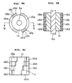
- the alternating motor 6 of the instant reaction force generating apparatus 2 has the parallelogrammatic first and second permanent magnets 16 and 18 which are arranged, as shown in Figs. 5A, 5B and 5C, along the outer peripheral surface of the rotor 14 such that the peripheral edges of the first and second permanent magnets 16 and 18 are disposed at an angle relative to the rotational axis of the rotor 14. Because of the inclined peripheral edges 16a, 16b, 18a and 18b of the first and second permanent magnets 16 and 18, the area on the permanent magnets 16 and 18, within the magnetic field, that faces the magnetic poles of the stator 12 changes. A sufficient amount of torque can be generated at the rotor 14, even when the change in relative position between the magnetic poles (indicated by broken line in Fig.
- the first and second permanent magnets 16 and 18 had larger surface areas than the area of the magnetic field generated by the coils, and their peripheral edges were parallel to the rotational axis of the rotor 14 and the change of relative position between the magnetic pole of the stator 12 and the first and second permanent magnets 16 and 18 is small, a sufficient torque for the rotor 14 would not be generated. Therefore, in the vicinity of the stop angle of 180 degrees, the steering wheel 4 would have a wider play but no rotational reaction force. On the other hand, if the areas of the first and second permanent magnets 16 and 18 were smaller, the magnetic force at the rotor 14 would be scarce, resulting in an insufficient reaction force for the steering wheel 4.
- the reaction force generating apparatus 2 of the instant embodiment is operative even if the first and second permanent magnets 16 and 18 to be mounted on the rotor 14 have relatively large surface area.
- any change in the relative position between the magnetic pole of the stator 12 and the first and second permanent magnets 16 and 18 results in a change of surface area on the permanent magnets 16 and 18 that faces the magnetic poles of the stator 12. Therefore, even when the amount of rotational travel of the steering wheel 4 caused by the player is only a relatively small rotation from the stop angle of 180 degrees, or even when the voltage supply by controller 8 to the coils 28 is changed by a relatively small value, the reaction force generated at the steering wheel 4 is of a sufficient value. Moreover, since the change in the area on the first and second permanent magnets 16 and 18, where they oppose the magnetic pole of the stator 12, is gradual as the rotor 14 is rotated, an increasing torque is smoothly generated at the rotor 14.
- first and second permanent magnets 16 and 18 are parallelogrammatic members aligned along the outer peripheral surface of the rotor 14.
- the permanent magnets may be four semi-cylindrical members 46a - 46d and 48a - 48d, as shown in Figs.
- the pole teeth K of the stator 12 may be formed at an angle relative to the rotational axis of the rotor 14 to obtain a similar result.
- reaction force generating apparatus 2 is used for providing a rotational reaction force for the steering wheel 4 of a driving game machine
- present invention may be applied to other various members that are rotationally operated either manually or mechanically.
- an acceleration pedal of the driving game machine may be fixed to the rotational axle 6a of the alternating motor 6 such that a rotational reaction force is provided for the acceleration pedal.
- an arm gear of a body building machine that is rotated manually may be fixed to the rotational axle 6a of the alternating motor 6.
- springs, rubber, or other mechanical urging members can be dispensed with in providing a reaction force for the arm gear.
- a training person can set the training level in a non-stepwise manner.
- the present invention is also applicable to members that are not manually rotated.
- Such members that are indirectly rotated by, for example, a link mechanism may be fixed to the rotational axle 6a of the alternating motor 6 to attain a similar result.
Landscapes
- Engineering & Computer Science (AREA)
- Multimedia (AREA)
- Theoretical Computer Science (AREA)
- Power Engineering (AREA)
- Human Computer Interaction (AREA)
- Educational Administration (AREA)
- Business, Economics & Management (AREA)
- Physics & Mathematics (AREA)
- Aviation & Aerospace Engineering (AREA)
- Educational Technology (AREA)
- General Physics & Mathematics (AREA)
- Permanent Magnet Type Synchronous Machine (AREA)
- Reciprocating, Oscillating Or Vibrating Motors (AREA)
- Connection Of Motors, Electrical Generators, Mechanical Devices, And The Like (AREA)
- Steering Control In Accordance With Driving Conditions (AREA)
- Power Steering Mechanism (AREA)
- Vehicle Body Suspensions (AREA)
Claims (8)
- Reaktionskraft-Erzeugungsvorrichtung zum Bereitstellen einer Reaktionskraft für ein drehend betätigtes Glied (4), welche aufweist:einen Wechselstrom-Motor (6) mit einem Stator (12), der eine Vielzahl von Wicklungen (28) hat, die, wenn ihnen ein Wechselstrom zugeführt wird, ein sich drehendes Magnetfeld erzeugen, einem Rotor (14), der an seiner äußeren peripheren Oberfläche befestigte Permanentmagnete (16, 18) hat, und einer Drehachse (6a), die sich von der Mitte des Rotors (14) axial weg erstreckt und ein außerhalb von dem Wechselstrom-Motor (6) angeordnetes äußeres Ende hat;wobei eine Betätigungsvorrichtung (8) jeder der Vielzahl von Wicklungen (28) des Wechselstrom-Motors (6) einen jeweiligen vorbestimmten Gleichstrom zuführt, um ein stationäres Magnetfeld zu erzeugen, das auf die Magnete (16, 18) an dem Rotor (14) einwirkt und die Drehachse (6a) in einer vorbestimmten Winkelposition hält; undwobei das drehend betätigte Glied (4), das an dem äußeren Ende der Drehachse (6a) befestigt ist, ein Lenkrad einer Fahrspiel-Maschine ist.
- Reaktionskraft-Erzeugungsvorrichtung zum Bereitstellen einer Reaktionskraft für ein drehend betätigtes Glied (4), welche aufweist:einen Wechselstrom-Motor (6) mit einem Stator (12), der eine Vielzahl von Wicklungen (28) hat, die, wenn ihnen ein Wechselstrom zugeführt wird, ein sich drehendes Magnetfeld erzeugen, einem Rotor (14), der an seiner äußeren peripheren Oberfläche befestigte Permanentmagnete (16, 18) hat, und einer Drehachse (6a), die sich von der Mitte des Rotors (14) axial weg erstreckt und ein außerhalb von dem Wechselstrom-Motor (6) angeordnetes äußeres Ende hat;wobei eine Betätigungsvorrichtung (8) jeder der Vielzahl von Wicklungen (28) des Wechselstrom-Motors (6) einen jeweiligen vorbestimmten Gleichstrom zuführt, um ein stationäres Magnetfeld zu erzeugen, das auf die Magnete (16, 18) an dem Rotor (14) einwirkt und die Drehachse (6a) in einer vorbestimmten Winkelposition hält; undwobei das drehend betätigte Glied (4) an dem äußeren Ende der Drehachse (6a) befestigt ist und wobei die Betätigungsvorrichtung (8) einen Mechanismus enthält zum abwechselnder Ändern des Gleichstroms, der jeder der Vielzahl von Wicklungen (28) des Wechselstrom-Motors (6) mit einer vorbestimmten Frequenz über eine vorbestimmte Zeitdauer hinweg zugeführt wird.
- Reaktionskraft-Erzeugungsvorrichtung nach Anspruch 1 oder 2, bei welcher die Permanentmagnete (16, 18) in einem Winkel relativ zur Drehachse des Rotors (14) angeordnet sind.
- Reaktionskraft-Erzeugungsvorrichtung nach Anspruch 1 oder 2, bei welcher der Stator (12) Polzähne enthält, die in einem Winkel relativ zur Drehachse des Rotors (14) angeordnet sind.
- Verfahren zum Erzeugen einer Reaktionskraft für ein drehend betätigtes Glied (4), welches die folgenden Schritte aufweist:Bereitstellen eines Wechselstrom-Motors (6) mit einem Stator (12), der eine Vielzahl von Wicklungen (28) hat, die, wenn ihnen ein Wechselstrom zugeführt wird, ein sich drehendes Magnetfeld erzeugen, einem Rotor (14), der an seiner äußeren peripheren Oberfläche befestigte Permanentmagnete (16, 18) hat, und einer Drehachse (6a), die sich von der Mitte des Rotors (14) axial weg erstreckt und ein außerhalb von dem Wechselstrom-Motor (6) angeordnetes äußeres Ende hat, und wobei das drehend betätigte Glied (4), das an dem äußeren Ende der Drehachse (6a) befestigt ist, ein Lenkrad einer Fahrspiel-Maschine ist; undZuführen eines jeweiligen vorbestimmten Gleichstroms an jede der Vielzahl von Wicklungen (28) des Wechselstrom-Motors (6), um dadurch ein stationäres magnetfeld zu erzeugen, das auf die Magnete (16, 18) an dem Rotor (14) einwirkt und die Drehachse (6a) in einer vorbestimmten Winkelposition hält.
- Verfahren zum Erzeugen einer Reaktionskraft für ein drehend betätigtes Glied (4), welches die folgenden Schritte aufweist:Bereitstellen eines Wechselstrom-Motors (6) mit einem Stator (12), der eine Vielzahl von Wicklungen (28) hat, die, wenn ihnen ein Wechselstrom zugeführt wird, ein sich drehendes Magnetfeld erzeugen, einem Rotor (14), der an seiner äußeren peripheren Oberfläche befestigte Permanentmagnete (16, 18) hat, und einer Drehachse (6a), die sich von der Mitte des Rotors (14) axial weg erstreckt und ein außerhalb von dem Wechselstrom-Motor (6) angeordnetes äußeres Ende hat, und wobei das drehend betätigte Glied (4) an dem äußeren Ende der Drehachse (6a) befestigt ist; undZuführen eines jeweiligen vorbestimmten Gleichstroms an jede der Vielzahl von Wicklungen (28) des Wechselstrom-Motors (6), um dadurch ein stationäres Magnetfeld zu erzeugen, das auf die Magnete (16, 18) an dem Rotor (14) einwirkt und die Drehachse (6a) in einer vorbestimmten Winkelposition hält; und außerdem einen Schritt aufweist zum abwechselnden Ändern des Gleichstroms, der jeder der Vielzahl von Wicklungen (28) des Wechselstrom-Motors (6) mit einer vorbestimmten Frequenz über eine vorbestimmte Zeitdauer hinweg zugeführt wird.
- Verfahren zum Erzeugen einer Reaktionskraft nach Anspruch 5 oder 6, welches außerdem einen Schritt zum Anordnen der Permanentmagnete (16, 18) in einem Winkel relativ zur Drehachse des Rotors (14) aufweist.
- Verfahren zum Erzeugen einer Reaktionskraft nach Anspruch 5 oder 6, welches außerdem einen Schritt zum Bereitstellen von Polzähnen, an dem Stator und Anordnen der Polzähne in einem Winkel relativ zur Drehachse des Rotors (14) aufweist, wobei die Vielzahl der Wicklungen (28) um die Polzähne herum gewickelt werden.
Applications Claiming Priority (2)
| Application Number | Priority Date | Filing Date | Title |
|---|---|---|---|
| JP84626/94 | 1994-04-22 | ||
| JP6084626A JP2665313B2 (ja) | 1994-04-22 | 1994-04-22 | 反力発生装置 |
Publications (2)
| Publication Number | Publication Date |
|---|---|
| EP0680132A1 EP0680132A1 (de) | 1995-11-02 |
| EP0680132B1 true EP0680132B1 (de) | 1998-12-09 |
Family
ID=13835894
Family Applications (1)
| Application Number | Title | Priority Date | Filing Date |
|---|---|---|---|
| EP95105923A Expired - Lifetime EP0680132B1 (de) | 1994-04-22 | 1995-04-20 | Vorrichtung zum Erzeugen einer Reaktionskraft |
Country Status (5)
| Country | Link |
|---|---|
| US (1) | US5656901A (de) |
| EP (1) | EP0680132B1 (de) |
| JP (1) | JP2665313B2 (de) |
| AT (1) | ATE174455T1 (de) |
| DE (1) | DE69506471D1 (de) |
Cited By (1)
| Publication number | Priority date | Publication date | Assignee | Title |
|---|---|---|---|---|
| US6704001B1 (en) | 1995-11-17 | 2004-03-09 | Immersion Corporation | Force feedback device including actuator with moving magnet |
Families Citing this family (72)
| Publication number | Priority date | Publication date | Assignee | Title |
|---|---|---|---|---|
| US5889670A (en) | 1991-10-24 | 1999-03-30 | Immersion Corporation | Method and apparatus for tactilely responsive user interface |
| US6437771B1 (en) | 1995-01-18 | 2002-08-20 | Immersion Corporation | Force feedback device including flexure member between actuator and user object |
| US6057828A (en) * | 1993-07-16 | 2000-05-02 | Immersion Corporation | Method and apparatus for providing force sensations in virtual environments in accordance with host software |
| US5739811A (en) | 1993-07-16 | 1998-04-14 | Immersion Human Interface Corporation | Method and apparatus for controlling human-computer interface systems providing force feedback |
| US5734373A (en) * | 1993-07-16 | 1998-03-31 | Immersion Human Interface Corporation | Method and apparatus for controlling force feedback interface systems utilizing a host computer |
| US5805140A (en) | 1993-07-16 | 1998-09-08 | Immersion Corporation | High bandwidth force feedback interface using voice coils and flexures |
| US5821920A (en) | 1994-07-14 | 1998-10-13 | Immersion Human Interface Corporation | Control input device for interfacing an elongated flexible object with a computer system |
| US5691898A (en) | 1995-09-27 | 1997-11-25 | Immersion Human Interface Corp. | Safe and low cost computer peripherals with force feedback for consumer applications |
| US6166723A (en) | 1995-11-17 | 2000-12-26 | Immersion Corporation | Mouse interface device providing force feedback |
| US5959613A (en) | 1995-12-01 | 1999-09-28 | Immersion Corporation | Method and apparatus for shaping force signals for a force feedback device |
| FR2741175B1 (fr) * | 1995-11-10 | 1997-12-12 | Renault | Dispositif de restitution d'effort au volant d'un vehicule automobile a direction decouplee |
| US5825308A (en) | 1996-11-26 | 1998-10-20 | Immersion Human Interface Corporation | Force feedback interface having isotonic and isometric functionality |
| US6100874A (en) | 1995-11-17 | 2000-08-08 | Immersion Corporation | Force feedback mouse interface |
| WO1997020305A1 (en) | 1995-11-30 | 1997-06-05 | Virtual Technologies, Inc. | Tactile feedback man-machine interface device |
| US8508469B1 (en) | 1995-12-01 | 2013-08-13 | Immersion Corporation | Networked applications including haptic feedback |
| US6028593A (en) | 1995-12-01 | 2000-02-22 | Immersion Corporation | Method and apparatus for providing simulated physical interactions within computer generated environments |
| US6050718A (en) * | 1996-03-28 | 2000-04-18 | Immersion Corporation | Method and apparatus for providing high bandwidth force feedback with improved actuator feel |
| US6024576A (en) * | 1996-09-06 | 2000-02-15 | Immersion Corporation | Hemispherical, high bandwidth mechanical interface for computer systems |
| JP3263012B2 (ja) * | 1996-10-01 | 2002-03-04 | 株式会社ソニー・コンピュータエンタテインメント | ゲーム機用操作装置 |
| AU737919B2 (en) * | 1996-10-11 | 2001-09-06 | Sony Computer Entertainment Inc. | Operating device for game machine |
| US7489309B2 (en) | 1996-11-26 | 2009-02-10 | Immersion Corporation | Control knob with multiple degrees of freedom and force feedback |
| US6154201A (en) * | 1996-11-26 | 2000-11-28 | Immersion Corporation | Control knob with multiple degrees of freedom and force feedback |
| US6686911B1 (en) | 1996-11-26 | 2004-02-03 | Immersion Corporation | Control knob with control modes and force feedback |
| US6956558B1 (en) | 1998-03-26 | 2005-10-18 | Immersion Corporation | Rotary force feedback wheels for remote control devices |
| US6128006A (en) * | 1998-03-26 | 2000-10-03 | Immersion Corporation | Force feedback mouse wheel and other control wheels |
| US6636197B1 (en) | 1996-11-26 | 2003-10-21 | Immersion Corporation | Haptic feedback effects for control, knobs and other interface devices |
| CA2278726C (en) * | 1997-01-27 | 2004-08-31 | Immersion Corporation | Method and apparatus for providing high bandwidth, realistic force feedback including an improved actuator |
| GB9706447D0 (en) * | 1997-03-27 | 1997-10-15 | British Aerospace | Electronic control apparatus |
| US6020876A (en) | 1997-04-14 | 2000-02-01 | Immersion Corporation | Force feedback interface with selective disturbance filter |
| US6104382A (en) | 1997-10-31 | 2000-08-15 | Immersion Corporation | Force feedback transmission mechanisms |
| US6020875A (en) * | 1997-10-31 | 2000-02-01 | Immersion Corporation | High fidelity mechanical transmission system and interface device |
| US6243078B1 (en) | 1998-06-23 | 2001-06-05 | Immersion Corporation | Pointing device with forced feedback button |
| US6088019A (en) | 1998-06-23 | 2000-07-11 | Immersion Corporation | Low cost force feedback device with actuator for non-primary axis |
| US6211861B1 (en) | 1998-06-23 | 2001-04-03 | Immersion Corporation | Tactile mouse device |
| US20080055241A1 (en) * | 1998-03-26 | 2008-03-06 | Immersion Corporation | Systems and Methods for Haptic Feedback Effects for Control Knobs |
| US6067077A (en) * | 1998-04-10 | 2000-05-23 | Immersion Corporation | Position sensing for force feedback devices |
| US6697043B1 (en) | 1999-12-21 | 2004-02-24 | Immersion Corporation | Haptic interface device and actuator assembly providing linear haptic sensations |
| US6707443B2 (en) | 1998-06-23 | 2004-03-16 | Immersion Corporation | Haptic trackball device |
| US6184868B1 (en) | 1998-09-17 | 2001-02-06 | Immersion Corp. | Haptic feedback control devices |
| US6717573B1 (en) | 1998-06-23 | 2004-04-06 | Immersion Corporation | Low-cost haptic mouse implementations |
| US6429846B2 (en) | 1998-06-23 | 2002-08-06 | Immersion Corporation | Haptic feedback for touchpads and other touch controls |
| US7038667B1 (en) * | 1998-10-26 | 2006-05-02 | Immersion Corporation | Mechanisms for control knobs and other interface devices |
| WO2000026891A1 (en) * | 1998-11-04 | 2000-05-11 | Immersion Corporation | Force feedback device including actuator with moving magnet |
| US6283859B1 (en) * | 1998-11-10 | 2001-09-04 | Lord Corporation | Magnetically-controllable, active haptic interface system and apparatus |
| US6614420B1 (en) | 1999-02-22 | 2003-09-02 | Microsoft Corporation | Dual axis articulated electronic input device |
| US6664946B1 (en) | 1999-02-22 | 2003-12-16 | Microsoft Corporation | Dual axis articulated computer input device and method of operation |
| US7819741B1 (en) | 1999-03-23 | 2010-10-26 | Bally Gaming, Inc. | Slot machine with a second wheel game |
| US6705944B2 (en) * | 1999-03-23 | 2004-03-16 | Sierra Design Group | Multiple game apparatus and method |
| US7046229B1 (en) | 1999-04-20 | 2006-05-16 | Microsoft Corporation | Computer input device providing absolute and relative positional information |
| US6762745B1 (en) | 1999-05-10 | 2004-07-13 | Immersion Corporation | Actuator control providing linear and continuous force output |
| US6982696B1 (en) | 1999-07-01 | 2006-01-03 | Immersion Corporation | Moving magnet actuator for providing haptic feedback |
| US8169402B2 (en) | 1999-07-01 | 2012-05-01 | Immersion Corporation | Vibrotactile haptic feedback devices |
| US6693622B1 (en) | 1999-07-01 | 2004-02-17 | Immersion Corporation | Vibrotactile haptic feedback devices |
| US7561142B2 (en) | 1999-07-01 | 2009-07-14 | Immersion Corporation | Vibrotactile haptic feedback devices |
| DE20080209U1 (de) * | 1999-09-28 | 2001-08-09 | Immersion Corp | Steuerung von haptischen Empfindungen für Schnittstellenvorrichtungen mit Vibrotaktiler Rückkopplung |
| US6822635B2 (en) | 2000-01-19 | 2004-11-23 | Immersion Corporation | Haptic interface for laptop computers and other portable devices |
| JP2001246165A (ja) | 2000-03-07 | 2001-09-11 | Konami Co Ltd | ゲーム機用回転操作装置 |
| US7084854B1 (en) | 2000-09-28 | 2006-08-01 | Immersion Corporation | Actuator for providing tactile sensations and device for directional tactile sensations |
| US6748604B2 (en) * | 2002-05-30 | 2004-06-15 | Finger Fitting Products, Inc. | Glove massager |
| US8059088B2 (en) | 2002-12-08 | 2011-11-15 | Immersion Corporation | Methods and systems for providing haptic messaging to handheld communication devices |
| US8830161B2 (en) | 2002-12-08 | 2014-09-09 | Immersion Corporation | Methods and systems for providing a virtual touch haptic effect to handheld communication devices |
| GB2414319A (en) | 2002-12-08 | 2005-11-23 | Immersion Corp | Methods and systems for providing haptic messaging to handheld communication devices |
| JP4770538B2 (ja) * | 2006-03-24 | 2011-09-14 | 株式会社日立製作所 | 電気駆動車両、及び電気駆動車両の制御方法 |
| US8174512B2 (en) * | 2006-06-02 | 2012-05-08 | Immersion Corporation | Hybrid haptic device utilizing mechanical and programmable haptic effects |
| GB0617989D0 (en) * | 2006-09-13 | 2006-10-18 | Denne Phillip R M | Improvements in electrical machines |
| US8542105B2 (en) | 2009-11-24 | 2013-09-24 | Immersion Corporation | Handheld computer interface with haptic feedback |
| US9582178B2 (en) | 2011-11-07 | 2017-02-28 | Immersion Corporation | Systems and methods for multi-pressure interaction on touch-sensitive surfaces |
| TW201621162A (zh) * | 2014-12-09 | 2016-06-16 | 廖人立 | 車用輪壓式發電裝置 |
| JP6560929B2 (ja) * | 2015-08-04 | 2019-08-14 | 東レエンジニアリング株式会社 | 操作感覚再現装置 |
| US10421492B2 (en) * | 2016-12-29 | 2019-09-24 | Automotive Research & Testing Center | Assisted steering system with vibrational function for vehicles and method for controlling the same |
| US12298800B2 (en) * | 2021-04-21 | 2025-05-13 | Shenzhen Guli Technology Co., Ltd. | Hall joystick |
| US12071172B2 (en) | 2021-05-13 | 2024-08-27 | Toyota Research Institute, Inc. | Method for visualizing a steering angle and lateral boundaries for driver assist and safer driving |
Citations (2)
| Publication number | Priority date | Publication date | Assignee | Title |
|---|---|---|---|---|
| US4447793A (en) * | 1982-05-13 | 1984-05-08 | Racal-Mesl Microwave Limited | Rotary actuators |
| US5044956A (en) * | 1989-01-12 | 1991-09-03 | Atari Games Corporation | Control device such as a steering wheel for video vehicle simulator with realistic feedback forces |
Family Cites Families (18)
| Publication number | Priority date | Publication date | Assignee | Title |
|---|---|---|---|---|
| IT958064B (it) * | 1971-07-01 | 1973-10-20 | Ver Flugtechnische Werke | Disposizione di comando per una colonna di sterzo |
| AU6012173A (en) * | 1972-09-14 | 1975-03-13 | Koike Seiki K K | Diaphragm-assisted exposure control device and electro- magnetic rotary motion device |
| US4001659A (en) * | 1974-09-12 | 1977-01-04 | Headway Research, Inc. | Apparatus for spinning a microelectronic substrate |
| US4467262A (en) * | 1980-03-24 | 1984-08-21 | The Charles Stark Draper Laboratory, Inc. | Polyphase motor drive system with balanced modulation |
| JPS57206295A (en) * | 1981-06-12 | 1982-12-17 | Sony Corp | Controlling circuit for brushless motor |
| DE3221048C2 (de) * | 1982-06-04 | 1987-01-15 | Danfoss A/S, Nordborg | Stellantrieb für ein Verstellorgan wie Ventil oder Klappe |
| FR2580101A1 (en) * | 1985-04-09 | 1986-10-10 | Thomson Csf | Force restoring system with electric torque motor |
| US4642539A (en) * | 1985-06-10 | 1987-02-10 | Northern Magnetics, Inc. | Torque motor with unlimited angular excursion |
| KR880002475B1 (ko) * | 1985-08-21 | 1988-11-14 | 이이수 | 직류 다상 양극성 무정류자 전동기 |
| US4884016A (en) * | 1988-08-23 | 1989-11-28 | Aerotech, Inc. | Closed loop torque angle control of synchronous motor |
| JP2704642B2 (ja) * | 1988-10-04 | 1998-01-26 | 株式会社タイトー | ゲーム機械用ステアリング装置 |
| JP2704647B2 (ja) * | 1988-10-25 | 1998-01-26 | 株式会社タイトー | ゲーム機械用のステアリング装置 |
| US4928043A (en) * | 1988-11-14 | 1990-05-22 | Synektron Corporation | Back EMF sampling circuit for phase locked loop motor control |
| NL8803148A (nl) * | 1988-12-23 | 1990-07-16 | Philips Corp | Inrichting met een actuator, een werkwijze voor toepassing in de inrichting, en een systeem voor het regelen van een gas of vloeistof stroom, omvattende de inrichting. |
| JPH06103995B2 (ja) * | 1989-05-31 | 1994-12-14 | 日本ビクター株式会社 | センサレス方式ブラシレスモータ |
| JP2637564B2 (ja) * | 1989-08-03 | 1997-08-06 | 三菱電機株式会社 | モータコントローラ回路内蔵マイクロコンピュータ |
| JPH0492691A (ja) * | 1990-08-07 | 1992-03-25 | Taito Corp | ステアリング操作装置 |
| JP3190359B2 (ja) * | 1990-12-28 | 2001-07-23 | 株式会社ナムコ | ドライビングシミュレータのステアリング反力発生装置及び演算方法 |
-
1994
- 1994-04-22 JP JP6084626A patent/JP2665313B2/ja not_active Expired - Fee Related
-
1995
- 1995-04-20 AT AT95105923T patent/ATE174455T1/de not_active IP Right Cessation
- 1995-04-20 EP EP95105923A patent/EP0680132B1/de not_active Expired - Lifetime
- 1995-04-20 DE DE69506471T patent/DE69506471D1/de not_active Expired - Lifetime
- 1995-04-21 US US08/432,362 patent/US5656901A/en not_active Expired - Fee Related
Patent Citations (2)
| Publication number | Priority date | Publication date | Assignee | Title |
|---|---|---|---|---|
| US4447793A (en) * | 1982-05-13 | 1984-05-08 | Racal-Mesl Microwave Limited | Rotary actuators |
| US5044956A (en) * | 1989-01-12 | 1991-09-03 | Atari Games Corporation | Control device such as a steering wheel for video vehicle simulator with realistic feedback forces |
Cited By (1)
| Publication number | Priority date | Publication date | Assignee | Title |
|---|---|---|---|---|
| US6704001B1 (en) | 1995-11-17 | 2004-03-09 | Immersion Corporation | Force feedback device including actuator with moving magnet |
Also Published As
| Publication number | Publication date |
|---|---|
| JPH07293620A (ja) | 1995-11-07 |
| DE69506471D1 (de) | 1999-01-21 |
| JP2665313B2 (ja) | 1997-10-22 |
| ATE174455T1 (de) | 1998-12-15 |
| US5656901A (en) | 1997-08-12 |
| EP0680132A1 (de) | 1995-11-02 |
Similar Documents
| Publication | Publication Date | Title |
|---|---|---|
| EP0680132B1 (de) | Vorrichtung zum Erzeugen einer Reaktionskraft | |
| EP0901214B1 (de) | Wechselstrommotor mit Magneten sowie Verfahren zu dessen Konstruktion | |
| KR100679360B1 (ko) | 브러쉬리스 모터 제어를 위한 위상선도 각도 최적화 시스템 | |
| CA2387158A1 (en) | For driving step motors without overshoot | |
| US5583411A (en) | Synchronous motor control system for electric vehicle | |
| ATE164470T1 (de) | Interaktives, drehbares regelsystem mit taktiler rückführung | |
| US5786673A (en) | Electric motor | |
| CH673751GA3 (de) | ||
| KR102307178B1 (ko) | 모터로 구동되는 차량에서의 승차감 제어 장치 및 방법 | |
| US5661379A (en) | Electric motor | |
| KR20100028089A (ko) | 3상 브러시레스 모터의 제어 장치 | |
| US6376955B1 (en) | Motor/generator with multiple rotors | |
| JPH10184758A (ja) | 回転制御装置 | |
| EP1398868B1 (de) | Vorrichtung und Verfahren zum Betreiben eines bürstenlosen Motors | |
| Kim et al. | Torque ripple reduction of BLDC traction motor of electric wheelchair for ride comfort improvement | |
| JP3397489B2 (ja) | 電動車両の速度制御方法 | |
| EP1527979B1 (de) | Elektrische Servolenkung für ein Fahrzeug | |
| US12381503B2 (en) | Method for adjusting an operational performance of an electric machine, data processing device, computer program, computer-readable storage medium, and electric drive system | |
| JP2821052B2 (ja) | 電気自動車の駆動モータ制御装置 | |
| JP3342429B2 (ja) | ステッピングモータ | |
| JPH082758B2 (ja) | 液圧式パワーステアリング装置 | |
| JPH07308405A (ja) | 足踏み式運動機 | |
| JP3243909B2 (ja) | 電動車両用ブラシレス直流電動機の駆動方法 | |
| JPH0779588A (ja) | Srモータの制御装置 | |
| JP2641198B2 (ja) | ブラシレスモータ |
Legal Events
| Date | Code | Title | Description |
|---|---|---|---|
| PUAI | Public reference made under article 153(3) epc to a published international application that has entered the european phase |
Free format text: ORIGINAL CODE: 0009012 |
|
| AK | Designated contracting states |
Kind code of ref document: A1 Designated state(s): AT BE CH DE DK ES FR GB GR IE IT LI LU MC NL PT SE |
|
| 17P | Request for examination filed |
Effective date: 19960418 |
|
| 17Q | First examination report despatched |
Effective date: 19970509 |
|
| GRAG | Despatch of communication of intention to grant |
Free format text: ORIGINAL CODE: EPIDOS AGRA |
|
| GRAG | Despatch of communication of intention to grant |
Free format text: ORIGINAL CODE: EPIDOS AGRA |
|
| GRAH | Despatch of communication of intention to grant a patent |
Free format text: ORIGINAL CODE: EPIDOS IGRA |
|
| GRAH | Despatch of communication of intention to grant a patent |
Free format text: ORIGINAL CODE: EPIDOS IGRA |
|
| GRAA | (expected) grant |
Free format text: ORIGINAL CODE: 0009210 |
|
| AK | Designated contracting states |
Kind code of ref document: B1 Designated state(s): AT BE CH DE DK ES FR GB GR IE IT LI LU MC NL PT SE |
|
| PG25 | Lapsed in a contracting state [announced via postgrant information from national office to epo] |
Ref country code: NL Free format text: LAPSE BECAUSE OF FAILURE TO SUBMIT A TRANSLATION OF THE DESCRIPTION OR TO PAY THE FEE WITHIN THE PRESCRIBED TIME-LIMIT Effective date: 19981209 Ref country code: LI Free format text: LAPSE BECAUSE OF FAILURE TO SUBMIT A TRANSLATION OF THE DESCRIPTION OR TO PAY THE FEE WITHIN THE PRESCRIBED TIME-LIMIT Effective date: 19981209 Ref country code: IT Free format text: LAPSE BECAUSE OF FAILURE TO SUBMIT A TRANSLATION OF THE DESCRIPTION OR TO PAY THE FEE WITHIN THE PRE;WARNING: LAPSES OF ITALIAN PATENTS WITH EFFECTIVE DATE BEFORE 2007 MAY HAVE OCCURRED AT ANY TIME BEFORE 2007. THE CORRECT EFFECTIVE DATE MAY BE DIFFERENT FROM THE ONE RECORDED.SCRIBED TIME-LIMIT Effective date: 19981209 Ref country code: GR Free format text: LAPSE BECAUSE OF NON-PAYMENT OF DUE FEES Effective date: 19981209 Ref country code: FR Free format text: LAPSE BECAUSE OF FAILURE TO SUBMIT A TRANSLATION OF THE DESCRIPTION OR TO PAY THE FEE WITHIN THE PRESCRIBED TIME-LIMIT Effective date: 19981209 Ref country code: ES Free format text: THE PATENT HAS BEEN ANNULLED BY A DECISION OF A NATIONAL AUTHORITY Effective date: 19981209 Ref country code: CH Free format text: LAPSE BECAUSE OF FAILURE TO SUBMIT A TRANSLATION OF THE DESCRIPTION OR TO PAY THE FEE WITHIN THE PRESCRIBED TIME-LIMIT Effective date: 19981209 Ref country code: BE Free format text: LAPSE BECAUSE OF FAILURE TO SUBMIT A TRANSLATION OF THE DESCRIPTION OR TO PAY THE FEE WITHIN THE PRESCRIBED TIME-LIMIT Effective date: 19981209 Ref country code: AT Free format text: LAPSE BECAUSE OF FAILURE TO SUBMIT A TRANSLATION OF THE DESCRIPTION OR TO PAY THE FEE WITHIN THE PRESCRIBED TIME-LIMIT Effective date: 19981209 |
|
| REF | Corresponds to: |
Ref document number: 174455 Country of ref document: AT Date of ref document: 19981215 Kind code of ref document: T |
|
| REG | Reference to a national code |
Ref country code: CH Ref legal event code: EP |
|
| REF | Corresponds to: |
Ref document number: 69506471 Country of ref document: DE Date of ref document: 19990121 |
|
| REG | Reference to a national code |
Ref country code: IE Ref legal event code: FG4D |
|
| PG25 | Lapsed in a contracting state [announced via postgrant information from national office to epo] |
Ref country code: SE Free format text: LAPSE BECAUSE OF FAILURE TO SUBMIT A TRANSLATION OF THE DESCRIPTION OR TO PAY THE FEE WITHIN THE PRESCRIBED TIME-LIMIT Effective date: 19990309 Ref country code: PT Free format text: LAPSE BECAUSE OF FAILURE TO SUBMIT A TRANSLATION OF THE DESCRIPTION OR TO PAY THE FEE WITHIN THE PRESCRIBED TIME-LIMIT Effective date: 19990309 Ref country code: DK Free format text: LAPSE BECAUSE OF FAILURE TO SUBMIT A TRANSLATION OF THE DESCRIPTION OR TO PAY THE FEE WITHIN THE PRESCRIBED TIME-LIMIT Effective date: 19990309 |
|
| PG25 | Lapsed in a contracting state [announced via postgrant information from national office to epo] |
Ref country code: DE Free format text: LAPSE BECAUSE OF FAILURE TO SUBMIT A TRANSLATION OF THE DESCRIPTION OR TO PAY THE FEE WITHIN THE PRESCRIBED TIME-LIMIT Effective date: 19990310 |
|
| PG25 | Lapsed in a contracting state [announced via postgrant information from national office to epo] |
Ref country code: LU Free format text: LAPSE BECAUSE OF NON-PAYMENT OF DUE FEES Effective date: 19990420 Ref country code: IE Free format text: LAPSE BECAUSE OF NON-PAYMENT OF DUE FEES Effective date: 19990420 |
|
| NLV1 | Nl: lapsed or annulled due to failure to fulfill the requirements of art. 29p and 29m of the patents act | ||
| EN | Fr: translation not filed | ||
| REG | Reference to a national code |
Ref country code: CH Ref legal event code: PL |
|
| PLBE | No opposition filed within time limit |
Free format text: ORIGINAL CODE: 0009261 |
|
| STAA | Information on the status of an ep patent application or granted ep patent |
Free format text: STATUS: NO OPPOSITION FILED WITHIN TIME LIMIT |
|
| PG25 | Lapsed in a contracting state [announced via postgrant information from national office to epo] |
Ref country code: MC Free format text: LAPSE BECAUSE OF NON-PAYMENT OF DUE FEES Effective date: 19991031 |
|
| 26N | No opposition filed | ||
| REG | Reference to a national code |
Ref country code: IE Ref legal event code: MM4A |
|
| PGFP | Annual fee paid to national office [announced via postgrant information from national office to epo] |
Ref country code: GB Payment date: 20010410 Year of fee payment: 7 |
|
| REG | Reference to a national code |
Ref country code: GB Ref legal event code: IF02 |
|
| PG25 | Lapsed in a contracting state [announced via postgrant information from national office to epo] |
Ref country code: GB Free format text: LAPSE BECAUSE OF NON-PAYMENT OF DUE FEES Effective date: 20020420 |
|
| GBPC | Gb: european patent ceased through non-payment of renewal fee |
Effective date: 20020420 |