EP0680164A2 - Optisches Fasersystem mit sich verschmälender Faser - Google Patents
Optisches Fasersystem mit sich verschmälender Faser Download PDFInfo
- Publication number
- EP0680164A2 EP0680164A2 EP95302574A EP95302574A EP0680164A2 EP 0680164 A2 EP0680164 A2 EP 0680164A2 EP 95302574 A EP95302574 A EP 95302574A EP 95302574 A EP95302574 A EP 95302574A EP 0680164 A2 EP0680164 A2 EP 0680164A2
- Authority
- EP
- European Patent Office
- Prior art keywords
- fiber
- optical fiber
- optical
- cutoff
- wavelength
- Prior art date
- Legal status (The legal status is an assumption and is not a legal conclusion. Google has not performed a legal analysis and makes no representation as to the accuracy of the status listed.)
- Withdrawn
Links
Images

Classifications
-
- G—PHYSICS
- G02—OPTICS
- G02B—OPTICAL ELEMENTS, SYSTEMS OR APPARATUS
- G02B6/00—Light guides; Structural details of arrangements comprising light guides and other optical elements, e.g. couplings
- G02B6/24—Coupling light guides
- G02B6/26—Optical coupling means
- G02B6/28—Optical coupling means having data bus means, i.e. plural waveguides interconnected and providing an inherently bidirectional system by mixing and splitting signals
- G02B6/293—Optical coupling means having data bus means, i.e. plural waveguides interconnected and providing an inherently bidirectional system by mixing and splitting signals with wavelength selective means
- G02B6/29331—Optical coupling means having data bus means, i.e. plural waveguides interconnected and providing an inherently bidirectional system by mixing and splitting signals with wavelength selective means operating by evanescent wave coupling
- G02B6/29332—Wavelength selective couplers, i.e. based on evanescent coupling between light guides, e.g. fused fibre couplers with transverse coupling between fibres having different propagation constant wavelength dependency
-
- G—PHYSICS
- G02—OPTICS
- G02B—OPTICAL ELEMENTS, SYSTEMS OR APPARATUS
- G02B6/00—Light guides; Structural details of arrangements comprising light guides and other optical elements, e.g. couplings
- G02B6/24—Coupling light guides
- G02B6/255—Splicing of light guides, e.g. by fusion or bonding
- G02B6/2552—Splicing of light guides, e.g. by fusion or bonding reshaping or reforming of light guides for coupling using thermal heating, e.g. tapering, forming of a lens on light guide ends
-
- G—PHYSICS
- G02—OPTICS
- G02B—OPTICAL ELEMENTS, SYSTEMS OR APPARATUS
- G02B6/00—Light guides; Structural details of arrangements comprising light guides and other optical elements, e.g. couplings
- G02B6/24—Coupling light guides
- G02B6/26—Optical coupling means
- G02B6/28—Optical coupling means having data bus means, i.e. plural waveguides interconnected and providing an inherently bidirectional system by mixing and splitting signals
- G02B6/293—Optical coupling means having data bus means, i.e. plural waveguides interconnected and providing an inherently bidirectional system by mixing and splitting signals with wavelength selective means
- G02B6/29304—Optical coupling means having data bus means, i.e. plural waveguides interconnected and providing an inherently bidirectional system by mixing and splitting signals with wavelength selective means operating by diffraction, e.g. grating
- G02B6/29316—Light guides comprising a diffractive element, e.g. grating in or on the light guide such that diffracted light is confined in the light guide
- G02B6/29323—Coupling to or out of the diffractive element through the lateral surface of the light guide
-
- G—PHYSICS
- G02—OPTICS
- G02B—OPTICAL ELEMENTS, SYSTEMS OR APPARATUS
- G02B6/00—Light guides; Structural details of arrangements comprising light guides and other optical elements, e.g. couplings
- G02B6/24—Coupling light guides
- G02B6/26—Optical coupling means
- G02B6/28—Optical coupling means having data bus means, i.e. plural waveguides interconnected and providing an inherently bidirectional system by mixing and splitting signals
- G02B6/293—Optical coupling means having data bus means, i.e. plural waveguides interconnected and providing an inherently bidirectional system by mixing and splitting signals with wavelength selective means
- G02B6/29379—Optical coupling means having data bus means, i.e. plural waveguides interconnected and providing an inherently bidirectional system by mixing and splitting signals with wavelength selective means characterised by the function or use of the complete device
- G02B6/2938—Optical coupling means having data bus means, i.e. plural waveguides interconnected and providing an inherently bidirectional system by mixing and splitting signals with wavelength selective means characterised by the function or use of the complete device for multiplexing or demultiplexing, i.e. combining or separating wavelengths, e.g. 1xN, NxM
-
- G—PHYSICS
- G02—OPTICS
- G02B—OPTICAL ELEMENTS, SYSTEMS OR APPARATUS
- G02B6/00—Light guides; Structural details of arrangements comprising light guides and other optical elements, e.g. couplings
- G02B6/24—Coupling light guides
- G02B6/42—Coupling light guides with opto-electronic elements
- G02B6/4201—Packages, e.g. shape, construction, internal or external details
- G02B6/4246—Bidirectionally operating package structures
-
- G—PHYSICS
- G02—OPTICS
- G02B—OPTICAL ELEMENTS, SYSTEMS OR APPARATUS
- G02B6/00—Light guides; Structural details of arrangements comprising light guides and other optical elements, e.g. couplings
- G02B6/02—Optical fibres with cladding with or without a coating
- G02B6/036—Optical fibres with cladding with or without a coating core or cladding comprising multiple layers
- G02B6/03605—Highest refractive index not on central axis
- G02B6/03611—Highest index adjacent to central axis region, e.g. annular core, coaxial ring, centreline depression affecting waveguiding
-
- G—PHYSICS
- G02—OPTICS
- G02B—OPTICAL ELEMENTS, SYSTEMS OR APPARATUS
- G02B6/00—Light guides; Structural details of arrangements comprising light guides and other optical elements, e.g. couplings
- G02B6/02—Optical fibres with cladding with or without a coating
- G02B6/036—Optical fibres with cladding with or without a coating core or cladding comprising multiple layers
- G02B6/03616—Optical fibres characterised both by the number of different refractive index layers around the central core segment, i.e. around the innermost high index core layer, and their relative refractive index difference
- G02B6/03622—Optical fibres characterised both by the number of different refractive index layers around the central core segment, i.e. around the innermost high index core layer, and their relative refractive index difference having 2 layers only
-
- G—PHYSICS
- G02—OPTICS
- G02B—OPTICAL ELEMENTS, SYSTEMS OR APPARATUS
- G02B6/00—Light guides; Structural details of arrangements comprising light guides and other optical elements, e.g. couplings
- G02B6/02—Optical fibres with cladding with or without a coating
- G02B6/036—Optical fibres with cladding with or without a coating core or cladding comprising multiple layers
- G02B6/03616—Optical fibres characterised both by the number of different refractive index layers around the central core segment, i.e. around the innermost high index core layer, and their relative refractive index difference
- G02B6/03638—Optical fibres characterised both by the number of different refractive index layers around the central core segment, i.e. around the innermost high index core layer, and their relative refractive index difference having 3 layers only
- G02B6/03644—Optical fibres characterised both by the number of different refractive index layers around the central core segment, i.e. around the innermost high index core layer, and their relative refractive index difference having 3 layers only arranged - + -
Definitions
- This invention relates to optical fiber systems, such as fiber communications and fiber sensing systems, and, in particular, to optical fiber systems provided with a tapered fiber device for filtering, wavelength shift detecting, or switching.
- Optical fibers are key components in modem telecommunications systems and in recently developed remote sensing systems.
- Optical fibers are thin strands of glass capable of transmitting an optical signal over long distances with very low loss.
- an optical fiber is a small diameter waveguide characterized by a core with a first index of refraction surrounded by one or more regions of cladding having lower indices of refraction.
- Light rays which impinge upon the core at an angle less than a critical acceptance angle undergo total internal reflection within the fiber core. These rays are guided along the axis of the fiber with minimum attenuation.
- Typical optical fibers are made of high purity silica with minor concentrations of dopants to control the index of refraction.
- a typical optical fiber communications system comprises a source of optical input signals, a length of optical fiber coupled to the source and a receiver for optical signals coupled to the fiber.
- One or more amplifying devices are disposed along the fiber for amplifying the transmitted signal.
- Current systems use single wavelength digitally modulated optical signals.
- Contemplated systems would use a plurality of wavelengths in multichannel wavelength division multiplexed (WDM) systems.
- Optical filtering devices are useful components in optical fiber communications systems and especially in WDM systems.
- sensing systems using optical fibers as sensing elements. See, for example, United States Patent No. 4,761,073 issued to Meltz et al. on August 2, 1988 which is incorporated herein by reference and United States Patent No. 4,950,883 issued to W. Glenn on August 21, 1990 which is also incorporated herein by reference.
- Such a system uses an optical fiber which includes along its length one or more photoinduced periodic gratings. In response to light transmitted along the fiber, each grating acts as a partial reflecting mirror for light of a narrow band of wavelengths corresponding to twice the periodicity of the grating.
- wavelength shift detectors are useful components in optical fiber sensing systems.
- An optical fiber system is provided with a tapered fiber device for filtering, wavelength shift detecting, or switching.
- a multiclad single mode optical fiber with a fundamental mode cutoff can be tapered to form a compact component useful in optical fiber systems, e.g. a filter in telecommunications systems, a wavelength shift detector in sensing systems, or a switch in any optical system.
- FIG. 1 is a cross section of a typical tapered fiber device which is essentially a multiclad single mode optical fiber 1 comprising an inner core 2 having a relatively high index of refraction surrounded by a plurality of cladding layers 3 and 4, having relatively lower indices of refraction as compared to the core.
- the fibers are drawn with a circular core 2 and concentric cladding layers 3, 4 in accordance with processes well known in the art.
- the core is typically germanium-doped silica
- the cladding layers are typically silica or fluorine-doped silica.
- the fiber is dimensioned for single mode operation.
- the core dimensions are typically a few microns or less, and cladding layers are typically a few microns to several tens of microns. Not shown in FIG. 1 is the fact that this fiber has been tapered as by heating it and stretching it along its longitudinal axis.
- Multiclad single mode optical fibers leak light of wavelength above a characteristic cutoff wavelength.
- such fiber will exhibit a typical cutoff spectral response.
- the loss mechanism is gradual, and in short lengths the cutoff loss is normally negligible.
- Applicant has discovered that by tapering these fibers, one can make a compact device exhibiting cutoff characteristics in short lengths of less than 1 meter and preferably on the order of a few centimeters.
- the effective cutoff wavelength and loss slope can be tailored to the needs of an optical system. This is illustrated by providing filters, shift detectors and switches for optical systems.
- FIG. 2 schematically illustrates an optical fiber telecommunications system 10 using a tapered fiber device as a filter.
- the system comprises a plurality of sources 11, 12 of optical signals at a respective plurality of wavelengths ⁇ 1, ⁇ 2 ( ⁇ 2 > ⁇ 1), a wavelength division multiplexer 13 for combining the optical signals, a length of optical transmission fiber 14, and a WDM demultiplexer 15 for separating the ⁇ 1 and ⁇ 2 signals, and a plurality of detectors 16, 17 for demodulating the respective signals.
- the demultiplexer 15 comprises a wavelength dependent coupler 18 for coupling the ⁇ 2 signal off fiber 14 and a tapered fiber device 19 for filtering any remaining ⁇ 2 signal from the ⁇ 1 branch.
- tapered fiber device 19 is a multiclad single mode optical fiber with a fundamental mode cutoff near ⁇ 2 (within ⁇ 500 nm of ⁇ 2 and preferably within ⁇ 150 nm). It is tapered to a minimum dimension such that ⁇ 2 is in the cutoff region while ⁇ 1 is not. So the ⁇ 2 signal is attenuated at least 3 dB while the ⁇ 1 signal passes with almost no loss.
- FIG. 3 illustrates the currently preferred way of making tapered waveguide device 19.
- a length of multiclad fiber 20 having a fundamental mode cutoff near ⁇ 2 is placed on mounts 21, 22 in a coupler station 23 between a source 24 of broadband light around ⁇ 2 and a spectrum analyzer 25.
- the fiber is locally heated, as by an oxypropane torch flame 26 (T> 1000°C), to the softening point and tapered by stretching while the intensity spectrum from analyzer 25 is monitored.
- T> 1000°C oxypropane torch flame 26
- the fundamental mode cutoff wavelength before tapering can be several hundred nanometers away from ⁇ 2, and the fiber can still be tapered for this application.
- the outer diameter of the fiber will have to be reduced so much that the resulting device will be mechanically weakened. It is therefore desirable that the fiber in its untapered form have a cutoff within ⁇ 150 nm of ⁇ 2.
- the design of multiclad single mode optical fibers to a desired cutoff is described in M. Monerie, "Propagation in Doubly Clad Single-Mode Fibers", IEEE J. of Quantum Elec., Vol. QE-18, No. 4, p. 535 (April 1982), which is incorporated herein by reference and in S.
- An alternative method of fabrication which may be more suitable for mass production is to place the fiber in an arc-fusion splicer and to provide an arc while straining the fiber.
- the fabrication of the device may be better understood by consideration of the following specific example useful in a WDM system where ⁇ 1 is 1.3 ⁇ m and ⁇ 2 is 1.55 ⁇ m.
- the starting point was a length of multiclad fiber having a core of silica doped with 10 mole % of Ge and three cladding layers.
- the first cladding layer was 1.5 mole % fluorine doped silica
- the second was 2 mole % of Ge doped silica
- the third was undoped silica.
- the fiber was drawn to a core diameter of 3.9 ⁇ m and an outer diameter of 116 ⁇ m.
- the first two cladding layers have thicknesses of 2.7 ⁇ m.
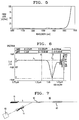
- the device had the refractive index profile shown in FIG. 4.
- the loss spectrum of the drawn fiber shown in FIG. 5 shows a fundamental mode cutoff with a steep rising loss edge at about 1.522 ⁇ m.
- a 6 cm length of the fiber was placed on a coupler station and heated with an oxypropane torch. Stretching the length to 6.2 cm produced the transmission spectrum shown in FIG. 6.
- the 10 dB isolation bandwidth is about 80 nm.
- FIG. 7 schematically illustrates an optical fiber sensing system 60 using a tapered waveguide to provide an inexpensive wavelength shift detector.
- the sensing system comprises a source 61 of optical energy around wavelength ⁇ , a length of optical fiber 62 including a reflective sensing grating 63 for reflecting light of wavelength ⁇ , a tapered fiber device 19 coupled to fiber 62 for receiving light reflected from grating 63 and a photodetector 65 for detecting the intensity of light through device 19.
- device 19 is tapered to a minimum dimension such that ⁇ in the output intensity spectrum is in the region of substantially linear slope near cutoff. In such a region, a shift ⁇ in the reflected wavelength will produce a substantially linear shift in the intensity output of device 19 which can be detected by photodetector 65.
- the system thus substitutes inexpensive components 19, 65 for the high cost spectrum analyzer of the prior art.
- the device 19 whose transmission characteristics are shown in FIG. 6 exhibits a 10 dB drop in power between 1450 nm and 1500 nm.
- the device thus provides a 0.2 dB/nm slope in that region for providing a useful wavelength shift detector.
- the tapered device can also be used as an optical switch for a source capable of transmitting at two wavelengths ( ⁇ 1 ⁇ ⁇ 2). By inserting a tapered device which transmits ⁇ 1 but cuts off ⁇ 2, the source is effectively switched off at the output of the tapered device when the source switches to ⁇ 2.
- the demultiplexer in FIG. 2 can be viewed as such a switch.
Landscapes
- Physics & Mathematics (AREA)
- General Physics & Mathematics (AREA)
- Optics & Photonics (AREA)
- Engineering & Computer Science (AREA)
- Plasma & Fusion (AREA)
- Optical Communication System (AREA)
- Light Guides In General And Applications Therefor (AREA)
- Optical Fibers, Optical Fiber Cores, And Optical Fiber Bundles (AREA)
- Optical Couplings Of Light Guides (AREA)
Applications Claiming Priority (2)
| Application Number | Priority Date | Filing Date | Title |
|---|---|---|---|
| US235575 | 1994-04-29 | ||
| US08/235,575 US5473714A (en) | 1994-04-29 | 1994-04-29 | Optical fiber system using tapered fiber devices |
Publications (2)
| Publication Number | Publication Date |
|---|---|
| EP0680164A2 true EP0680164A2 (de) | 1995-11-02 |
| EP0680164A3 EP0680164A3 (de) | 1997-01-22 |
Family
ID=22886074
Family Applications (1)
| Application Number | Title | Priority Date | Filing Date |
|---|---|---|---|
| EP95302574A Withdrawn EP0680164A3 (de) | 1994-04-29 | 1995-04-19 | Optisches Fasersystem mit sich verschmälender Faser. |
Country Status (3)
| Country | Link |
|---|---|
| US (1) | US5473714A (de) |
| EP (1) | EP0680164A3 (de) |
| JP (1) | JPH07301711A (de) |
Cited By (3)
| Publication number | Priority date | Publication date | Assignee | Title |
|---|---|---|---|---|
| EP0782020A3 (de) * | 1995-12-26 | 1998-01-07 | Nec Corporation | Optischer Wellenlängen-Filterkreis und sein Herstellungsverfahren |
| WO1999042871A1 (en) * | 1998-02-20 | 1999-08-26 | University Of Southampton | Optical device |
| US6282332B1 (en) * | 1998-06-04 | 2001-08-28 | Pirelli Cavi E Sistemi S.P.A. | Waveguide structures in particular for use in acousto-optical mode converters and method for making same |
Families Citing this family (14)
| Publication number | Priority date | Publication date | Assignee | Title |
|---|---|---|---|---|
| US5548671A (en) * | 1994-10-13 | 1996-08-20 | Northern Telecom Limited | Programmable, differential wavelength discriminator |
| US5717798A (en) * | 1996-09-12 | 1998-02-10 | Lucent Technologies Inc. | Optical waveguide system comprising a mode coupling grating and a mode discrimination coupler |
| US6301408B1 (en) | 1998-09-24 | 2001-10-09 | Lucent Technologies Inc | Tapered optical fiber grating devices with variable index coatings for modifying guide properties of the fundamental mode |
| US6362916B2 (en) * | 1998-09-25 | 2002-03-26 | Fiver Laboratories | All fiber gain flattening optical filter |
| US6445855B1 (en) * | 1999-05-25 | 2002-09-03 | Thomas & Betts International, Inc. | Method of fabricating fused and tapered couplers from optical fibers having photosensitive cladding regions |
| US6553165B1 (en) | 2000-07-14 | 2003-04-22 | Applied Wdm, Inc. | Optical waveguide gratings |
| US6493487B1 (en) | 2000-07-14 | 2002-12-10 | Applied Wdm, Inc. | Optical waveguide transmission devices |
| US6434303B1 (en) | 2000-07-14 | 2002-08-13 | Applied Wdm Inc. | Optical waveguide slab structures |
| US6563995B2 (en) | 2001-04-02 | 2003-05-13 | Lightwave Electronics | Optical wavelength filtering apparatus with depressed-index claddings |
| US6909538B2 (en) | 2002-03-08 | 2005-06-21 | Lightwave Electronics | Fiber amplifiers with depressed cladding and their uses in Er-doped fiber amplifiers for the S-band |
| US6970631B2 (en) | 2002-06-05 | 2005-11-29 | Lightwave Electronics | Suppression of cladding mode loss in fiber amplifiers with distributed suppression of amplified spontaneous emission (ASE) |
| US6995900B2 (en) * | 2003-01-21 | 2006-02-07 | Jds Uniphase Corporation | Method of making a short-pass fiber with controlled cut-off wavelength |
| JP5748319B2 (ja) * | 2006-07-25 | 2015-07-15 | ザ ボード オブ トラスティーズ オブ ザ レランド スタンフォード ジュニア ユニバーシティー | 中空コアのファイバテーパを用いる装置および方法 |
| CN111045145B (zh) * | 2019-12-25 | 2023-12-15 | 易锐光电科技(安徽)有限公司 | 薄膜光波导及其制备方法 |
Family Cites Families (9)
| Publication number | Priority date | Publication date | Assignee | Title |
|---|---|---|---|---|
| US4761073A (en) * | 1984-08-13 | 1988-08-02 | United Technologies Corporation | Distributed, spatially resolving optical fiber strain gauge |
| NL8502625A (nl) * | 1985-09-26 | 1987-04-16 | Philips Nv | Optisch transmissiesysteem bevattende een stralingsbron en een meervoudig beklede monomode optische transmissievezel met een negatieve stap in het brekingsindexprofiel. |
| GB8529861D0 (en) * | 1985-12-04 | 1986-01-15 | Gen Electric Co Ltd | Concatenated coupler |
| US4889404A (en) * | 1987-09-09 | 1989-12-26 | Corning Incorporated | Asymmetrical bidirectional telecommunication system |
| US4846540A (en) * | 1988-01-25 | 1989-07-11 | Bell Communications Research, Inc. | Optical wavegide junction |
| US4950883A (en) * | 1988-12-27 | 1990-08-21 | United Technologies Corporation | Fiber optic sensor arrangement having reflective gratings responsive to particular wavelengths |
| US4946250A (en) * | 1989-09-07 | 1990-08-07 | Ecole Polytechnique | Compact wavelength filter integrated to a single-mode optical fiber |
| GB2251957B (en) * | 1990-11-29 | 1993-12-15 | Toshiba Kk | Optical coupler |
| US5295211A (en) * | 1993-01-07 | 1994-03-15 | Corning Incorporated | Fiber amplifier coupler |
-
1994
- 1994-04-29 US US08/235,575 patent/US5473714A/en not_active Expired - Fee Related
-
1995
- 1995-04-19 EP EP95302574A patent/EP0680164A3/de not_active Withdrawn
- 1995-04-28 JP JP7104500A patent/JPH07301711A/ja not_active Withdrawn
Cited By (4)
| Publication number | Priority date | Publication date | Assignee | Title |
|---|---|---|---|---|
| EP0782020A3 (de) * | 1995-12-26 | 1998-01-07 | Nec Corporation | Optischer Wellenlängen-Filterkreis und sein Herstellungsverfahren |
| US5841929A (en) * | 1995-12-26 | 1998-11-24 | Nec Corporation | Light wavelength filtering circuit and manufacturing method thereof |
| WO1999042871A1 (en) * | 1998-02-20 | 1999-08-26 | University Of Southampton | Optical device |
| US6282332B1 (en) * | 1998-06-04 | 2001-08-28 | Pirelli Cavi E Sistemi S.P.A. | Waveguide structures in particular for use in acousto-optical mode converters and method for making same |
Also Published As
| Publication number | Publication date |
|---|---|
| EP0680164A3 (de) | 1997-01-22 |
| JPH07301711A (ja) | 1995-11-14 |
| US5473714A (en) | 1995-12-05 |
Similar Documents
| Publication | Publication Date | Title |
|---|---|---|
| US5473714A (en) | Optical fiber system using tapered fiber devices | |
| US5805751A (en) | Wavelength selective optical couplers | |
| US5459801A (en) | Coupler used to fabricate add-drop devices, dispersion compensators, amplifiers, oscillators, superluminescent devices, and communications systems | |
| US6850665B2 (en) | Wavelength-selective optical fiber components using cladding-mode assisted coupling | |
| US5457758A (en) | Add-drop device for a wavelength division multiple, fiber optic transmission system | |
| KR100330113B1 (ko) | 장주기스펙트럼형상디바이스및그를이용한광학시스템 | |
| US6360038B1 (en) | Wavelength-selective optical fiber components using cladding-mode assisted coupling | |
| US6362916B2 (en) | All fiber gain flattening optical filter | |
| US6005999A (en) | Waveguide narrowband rejection filter | |
| EP1271194B1 (de) | Gitter mit grosser Gitterperiode aufweisender optischer Bandpassfilter | |
| EP0829741A2 (de) | System optischer Wellenleiter mit einem Gitter zur Modenkopplung und einem Koppler zur Modenauswahl | |
| Mizrahi et al. | Four channel fibre grating demultiplexer | |
| EP0810749B1 (de) | Übertragungssystem mit preisgünstigem optischem Filter | |
| EP0831345A2 (de) | Faseroptisches Gitter | |
| US6445851B1 (en) | Tapered fiber gratings and applications | |
| US5550940A (en) | Optical tapping filters employing long period gratings | |
| KR20010071667A (ko) | 모놀리식 동축형 장치 | |
| EP0860733A1 (de) | Selbstabstimmendes optisches Wellenleiterfilter | |
| US6078709A (en) | Method and apparatus for monitoring multi-wavelength optical systems | |
| EP1330668B1 (de) | Faseroptisches filter | |
| Chu et al. | Tunable optical add-drop multiplexer based on silicon photonic wire waveguides | |
| KR20040068304A (ko) | 낮은 mpi의 분산 보상 광섬유 | |
| JP2003090918A (ja) | 長周期格子を使用する光学帯域通過フィルタ | |
| Reichelt et al. | Wavelength-division multi demultiplexers for two-channel single-mode transmission systems | |
| AU659499B2 (en) | An optical amplifier |
Legal Events
| Date | Code | Title | Description |
|---|---|---|---|
| PUAI | Public reference made under article 153(3) epc to a published international application that has entered the european phase |
Free format text: ORIGINAL CODE: 0009012 |
|
| AK | Designated contracting states |
Kind code of ref document: A2 Designated state(s): DE FR GB |
|
| PUAL | Search report despatched |
Free format text: ORIGINAL CODE: 0009013 |
|
| RHK1 | Main classification (correction) |
Ipc: G02B 6/00 |
|
| AK | Designated contracting states |
Kind code of ref document: A3 Designated state(s): DE FR GB |
|
| 17P | Request for examination filed |
Effective date: 19970709 |
|
| 17Q | First examination report despatched |
Effective date: 20020814 |
|
| STAA | Information on the status of an ep patent application or granted ep patent |
Free format text: STATUS: THE APPLICATION HAS BEEN WITHDRAWN |
|
| 18W | Application withdrawn |
Effective date: 20070215 |