EP0680873B1 - Gegendrehmomentvorrichtung mit einem eingelassenen Heckrotor und Abrichtstator und mit schrägen Richtleitschaufeln - Google Patents
Gegendrehmomentvorrichtung mit einem eingelassenen Heckrotor und Abrichtstator und mit schrägen Richtleitschaufeln Download PDFInfo
- Publication number
- EP0680873B1 EP0680873B1 EP95400998A EP95400998A EP0680873B1 EP 0680873 B1 EP0680873 B1 EP 0680873B1 EP 95400998 A EP95400998 A EP 95400998A EP 95400998 A EP95400998 A EP 95400998A EP 0680873 B1 EP0680873 B1 EP 0680873B1
- Authority
- EP
- European Patent Office
- Prior art keywords
- rotor
- duct
- blades
- approximately
- vein
- Prior art date
- Legal status (The legal status is an assumption and is not a legal conclusion. Google has not performed a legal analysis and makes no representation as to the accuracy of the status listed.)
- Expired - Lifetime
Links
- 230000005540 biological transmission Effects 0.000 claims description 23
- 230000008859 change Effects 0.000 claims description 11
- 238000011144 upstream manufacturing Methods 0.000 claims description 11
- 230000003247 decreasing effect Effects 0.000 claims description 7
- UJCHIZDEQZMODR-BYPYZUCNSA-N (2r)-2-acetamido-3-sulfanylpropanamide Chemical compound CC(=O)N[C@@H](CS)C(N)=O UJCHIZDEQZMODR-BYPYZUCNSA-N 0.000 claims description 6
- 241001669680 Dormitator maculatus Species 0.000 claims description 6
- 230000000750 progressive effect Effects 0.000 claims description 4
- 230000001747 exhibiting effect Effects 0.000 claims 1
- 230000002250 progressing effect Effects 0.000 claims 1
- 210000003462 vein Anatomy 0.000 description 106
- 230000006870 function Effects 0.000 description 18
- 230000003993 interaction Effects 0.000 description 11
- 238000009792 diffusion process Methods 0.000 description 7
- 230000009467 reduction Effects 0.000 description 7
- 230000007423 decrease Effects 0.000 description 6
- 238000001228 spectrum Methods 0.000 description 6
- 230000002093 peripheral effect Effects 0.000 description 5
- 230000006872 improvement Effects 0.000 description 4
- 230000001965 increasing effect Effects 0.000 description 4
- 230000001788 irregular Effects 0.000 description 4
- 230000008901 benefit Effects 0.000 description 3
- 230000010363 phase shift Effects 0.000 description 3
- 241000251556 Chordata Species 0.000 description 2
- 241000940835 Pales Species 0.000 description 2
- 206010033546 Pallor Diseases 0.000 description 2
- 230000000593 degrading effect Effects 0.000 description 2
- 230000007246 mechanism Effects 0.000 description 2
- 230000003071 parasitic effect Effects 0.000 description 2
- 230000036961 partial effect Effects 0.000 description 2
- 238000011084 recovery Methods 0.000 description 2
- 230000007704 transition Effects 0.000 description 2
- 229920000297 Rayon Polymers 0.000 description 1
- 238000004873 anchoring Methods 0.000 description 1
- 230000000712 assembly Effects 0.000 description 1
- 238000000429 assembly Methods 0.000 description 1
- 230000002238 attenuated effect Effects 0.000 description 1
- 230000006835 compression Effects 0.000 description 1
- 238000007906 compression Methods 0.000 description 1
- 238000010276 construction Methods 0.000 description 1
- 230000008602 contraction Effects 0.000 description 1
- 230000008094 contradictory effect Effects 0.000 description 1
- 238000012937 correction Methods 0.000 description 1
- 238000010586 diagram Methods 0.000 description 1
- 230000000694 effects Effects 0.000 description 1
- 230000000763 evoking effect Effects 0.000 description 1
- 230000005284 excitation Effects 0.000 description 1
- 230000002349 favourable effect Effects 0.000 description 1
- 230000000670 limiting effect Effects 0.000 description 1
- 238000004519 manufacturing process Methods 0.000 description 1
- 239000002184 metal Substances 0.000 description 1
- 230000004048 modification Effects 0.000 description 1
- 238000012986 modification Methods 0.000 description 1
- 238000005457 optimization Methods 0.000 description 1
- 238000005086 pumping Methods 0.000 description 1
- 239000002964 rayon Substances 0.000 description 1
- 230000002829 reductive effect Effects 0.000 description 1
- 230000000717 retained effect Effects 0.000 description 1
- 230000035945 sensitivity Effects 0.000 description 1
- 230000035939 shock Effects 0.000 description 1
- 230000003595 spectral effect Effects 0.000 description 1
- 230000003068 static effect Effects 0.000 description 1
Images
Classifications
-
- B—PERFORMING OPERATIONS; TRANSPORTING
- B64—AIRCRAFT; AVIATION; COSMONAUTICS
- B64C—AEROPLANES; HELICOPTERS
- B64C27/00—Rotorcraft; Rotors peculiar thereto
- B64C27/82—Rotorcraft; Rotors peculiar thereto characterised by the provision of an auxiliary rotor or fluid-jet device for counter-balancing lifting rotor torque or changing direction of rotorcraft
- B64C2027/8254—Shrouded tail rotors, e.g. "Fenestron" fans
Definitions
- the invention relates to improvements made anti-torque devices with rear rotor and stator fairing rectifiers for helicopters, in which the stator rectifier, comprising fixed blades with aerodynamic profile, is fixed downstream of the rotor in the flow stream of air arranged transversely in the hull integrated in the structure of the rear assemblies of a helicopter, such as the tail boom, the tail or a fin.
- the improvements made by the invention to devices anti-torque of this type can improve their performance acoustic and / or aerodynamic, to provide appreciable reduction in noise and noise pollution associated, as well as better yaw control, respectively.
- a faired anti-torque rotor prevents any risk accident on the ground, because it is protected inside the vein in the tail boom, unlike to a conventional tail rotor.
- This provision of faired anti-torque rotor also allows it to avoid ingest any harmful object that may be entrained in the wake of the main rotor.
- the faired anti-torque rotor In flight or in maneuver at near the ground or on the ground, the faired anti-torque rotor is naturally protected by its fairing, which prevents any risk of shock with external obstacles such as power lines, branches, constructions or even the ground, which can cause fatal damage to a rotor classic rear, and therefore the loss of the helicopter, with all the consequences for the crew.
- an anti-torque rotor streamlined eliminates a number of problems that manifest themselves when equipping a helicopter with a classic tail rotor.
- the diameter of a conventional tail rotor is generally important.
- a conventional tail rotor is generally mounted at a high point on the fin, which creates a moment roll on the helicopter, which must be balanced, and generates a parasitic trail in forward speed flight high. Due to its exposed position, a rear rotor classic can be highly stressed by loads dynamics limiting its lifespan.
- the effect of aerodynamic locking of a conventional rear rotor due to drift mask, generates strong behavior asymmetrical in crosswinds, and aerodynamic loads harmful impulse periodicals.
- a faired tail rotor does not have these disadvantages. In general, it can easily be arranged so that its axis substantially intersects the roll axis of the helicopter, or is close to this roll axis, so that it does not created no parasitic roll moment. In addition, due to its fairing, it produces approximately half of its total anti-torque boost by the sole phenomenon of suction by the collector, at the entrance of the vein which lodge. This makes it possible to discharge the rotor blades as much, which practically do not undergo dynamic stresses, due to the effective protection provided by the fairing vis-à-vis external variations of the air flow, in from the main rotor and the fuselage of the helicopter.
- the faired anti-torque rotor In forward flight at high speed of the latter, the faired anti-torque rotor is discharged, which decreases all the more its contribution to the overall drag of the device.
- the vertical drift possibly equipped with a turning flap, ensures the anti-torque function.
- no drift or tail plan hinders the operation of the faired anti-torque rotor, which provides maximum efficiency in crosswinds and during rapid maneuvers around the yaw axis.
- the diffusion ratio is close to 1, and can be increased by increasing the angle of divergence by one frustoconical part of the diffuser that the vein may include downstream of the plane of rotation of the rotor blades, as described for example in US patent US-5,131,604, where this divergence angle is limited to 5 °.
- the wake contraction on a conventional tail rotor freezes the diffusion ratio at 1/2, which prevents any improvement performance using this parameter.
- a streamlined tail rotor still takes advantage of its positioning in a vein of fairing: unlike a conventional tail rotor, which radiates noise in all directions, detectability a rear rotor faired forwards and backwards, in the direction of advancement of the helicopter, is greatly reduced due to the fairing.
- the combination of an angular speed of rotation ⁇ and a number of blades b higher on an anti-torque rotor faired that on a conventional tail rotor produces a "blade pass frequency" b x ⁇ and its frequencies multiples n b ⁇ which are much higher frequencies high acoustic energy concentration than for a classic tail rotor, and typically in the field of frequencies from 400 Hz to 2000 Hz. These frequencies are very quickly attenuated in the atmosphere, while the very low frequencies of acoustic energy concentration of a rotor classic rear spread far.
- a disadvantage of anti-torque rotors streamlined is that raising the frequency level of acoustic energy concentration places these in ear sensitivity maximum frequency zone human.
- the acoustic signature characteristic of an anti-torque rotor streamlined is also a damaging phenomenon, making it easier to identify the helicopter.
- the overall level of acoustic energy dissipated is the second main factor in judging the quality of the acoustic level of a helicopter.
- the aerodynamic operation of a faired anti-torque rotor with a high number of blades and for which the anti-torque thrust is provided for half by the suction causes a load per blade lower than that undergone by the blades of a conventional tail rotor, and therefore a lower charge noise level.
- US-5,131,604 proposes that the three support arms are of elliptical section, one being radial and aligned with the longitudinal axis of the helicopter and the other two parallel to the vertical axis of the fairing, but offset backwards, the spacing along the axis of the vein, between the plane of rotation of the rotor and the arms support being 2 to 2.5 times the minor axis of the ellipse of the arm section.
- the propeller has a number of blades even and greater than or equal to four, the blades being diametrically opposite two by two, and the pairs of blades being arranged offset from each other with an angular deviation pitch between approximately 15 ° and 50 °, so that the levels of the harmonics rotation noise are weakened by interference.
- An object of the invention is to propose improvements for the realization of an anti-torque device with rotor and stator rectifier shrouded in noise pollution designed to equip a helicopter powered by using a single main rotor, while retaining or even even by improving, the aerodynamic performance of the device fairing anti-torque, compared to known sets of this guy.
- an object of the invention is to propose a configuration and / or a layout of the rectifier according to the geometry of the rotor for minimize interaction noise, reducing energy radiated acoustics.
- Another object of the invention is to propose a streamlined vein configuration improving performance aerodynamics of the anti-torque device, that the blades of the whether or not the rotor is evenly distributed angularly, to increase the thrust level at given power, and reduce the noise caused by the air flow in the vein.
- the invention aims to offer an anti-torque device with rotor and stator streamlined rectifier, which better suits various requirements of practice that faired anti-torque devices known.
- an anti-torque device for helicopter comprising a multi-blade variable pitch rotor rotatably mounted and substantially coaxial in a vein air flow axis substantially transverse to the helicopter and crossing a hull integrated in the part rear of the helicopter, so that the axes of change pitch of the blades move in a plane of rotation substantially perpendicular to the axis of the streamlined vein, as well as a stator rectifier fixed in the vein downstream of the rotor and comprising stationary vanes arranged substantially in a star around the axis of the vein and each presenting an asymmetrical aerodynamic profile including camber and angular setting relative to the axis of the vein are such the blades straighten the air flow downstream of the rotor substantially parallel to the axis of the vein, and which characterized in that the stator vanes are each inclined in the radial direction, preferably by an angle from about 1 ° to about 25 °, from the axis of
- This orientation is simultaneously favorable to the resumption of the couple, exercising, in reaction to the rotation of the rotor, on a central body substantially coaxial with the vein, containing the rotor drive members and collective control members of the pitch of the blades of this last, and that the stator vanes can thus advantageously bear in the vein.
- each rectifier blade makes an angle not zero relative to the plane of rotation of the rotor blades, by being inclined towards the exit of the vein, allows increase the distance between the plane of rotation of blades of the local position of the leading edge of the blades of the rectifier, at the periphery of the vein, where the blades connect to the shrouded wall of this vein, and where the rotor-induced speed in the wake is the most high, and therefore generates a stronger interaction on the straightener than towards the foot of the blades.
- this distance (between 1.3 c and 2.5 c) is advantageous, in especially if the chord c is measured at the start of the current profiled part of the blade, to obtain a good trade-off between the level of radiated acoustic energy and the aerodynamic efficiency of the rectifier, and promote its arrangement in the vein of the anti-torque device, and particularly the anchoring of its blades in the faired wall of the vein, as well as to ensure proper positioning of the rotor in the vein, through the box rear transmission supported therein by the vanes.
- the blades fill in good conditions simultaneously their body support function central and their air flow straightening function crossing the vein, it is advantageous that they have an aerodynamic profile of type NACA 65, with a thickness relative between about 8% and about 12%, a angular setting on the axis of the vein between approximately 2 ° and about 2.5 °, oriented to prick, and a camber between approximately 20 ° and approximately 28 °.
- the thickness as well chosen is a compromise between a relative thickness the as low as possible, to decrease both the noise of load and thickness of the rectifier working in the wake of rotating blades, and sufficient thickness to maintain the body supporting the rotor and enclosing the rear gearbox and control collective pitch of the blades, which are thus joined to the rear assembly of the helicopter, comprising the end tail beam and tailplane or fin the helicopter, while being subjected to force fields static and dynamic.
- this arm is advantageously arranged in the vein substantially in place of one of the stator vanes, the profiled vanes of which are advantageously in number at least equal to the number of blades of the rotor decreased by one unit.
- a reduction in the nuisance acoustics and increased aerodynamic performance of a faired rotor anti-torque device can also be obtained by a geometric configuration particular of the vein, when the azimuth modulation blades is irregular or regular, and the rotor is or is not associated with a rectifier.
- the vein comprises two parts, of which one is a collector, corresponding to the part of the vein located upstream of the plane of rotation of the rotor, and the other is a diffuser, corresponding to the part of the vein located downstream of the rotor rotation plane, the collector comprising an inlet convergent, delimited by an annular wall convex upstream and rounded with a constant radius Rc, which extends towards the plane of rotation of the rotor by a cylindrical zone of a first length L1, and the diffuser comprising, from the plane of rotation from the rotor downstream, a cylindrical zone of one second length L2, extending the cylindrical area of the manifold, then a frustoconical divergence of half angle at the vertex ⁇ , and a divergent outlet delimited by an annular wall convex downstream, and rounded with radius r.
- the collector comprising an inlet convergent, delimited by an annular wall convex upstream and rounded with a constant radius Rc, which extends towards the plane
- the position of the plane of rotation of the rotor in this cylindrical part is defined as a function of the chord c of the blades of the rotor, of their positive pitch range, of the distance a between their leading edge and the axis of change. pitch, and the maximum deformation f of the blade, characterizing its stiffness in flapping, so that the lengths L1 and L2 of the cylindrical zones are such that: L1> a sin ( ⁇ max) + f and L2 ⁇ (c - a) sin ( ⁇ max) , where ⁇ max is the maximum positive pitch angle of the rotor blades.
- the lengths L1 and L2 of the cylindrical zones of the collector and of the diffuser are respectively between approximately 2% and about 8%, and between about 1% and about 3.5% of the diameter of the vein measured in its cylindrical part.
- the vein has a part cylindrical, since it includes a manifold inlet converging delimited by a convex annular wall and rounded with a constant radius Rc, this radius is approximately 8% of the diameter of the vein measured at its neck, in its tightest section.
- the angle of diffusion of the diffuser, or half-angle a of its tapered divergence is preferably chosen between about 5 ° and about 20 °.
- r1 is less than about 1.6% of the diameter of the vein, while r2 is between 4.3% of the diameter of the vein and the radius Rc chosen for the convergent of the collector, and the front area of constant radius r1 extends on an arc corresponding to an angle at the center of minus 210 °, while the rear zone, of constant radius r2, extends over an arc corresponding to an angle at 90 ° center, symmetrically above and below the longitudinal axis of the helicopter.
- the vein can be spared in a hull integrated into a rear part of a helicopter comprising the rear end of a tail boom and at least one tail fin
- the tail can be bi-drift and of a type included among the cruciform empennages, in T or V above the vein, and at least one tail fin that may include a fin flap steerable.
- the axis of the vein may possibly be tilted in the horizontal direction so that the thrust of the faired rotor produces a lift component on the helicopter.
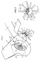
- the base of the empennage 2 is arranged in hull 5, transversely crossed by a flow vein 6 of air from a faired anti-torque device also comprising a multi-blade rotor 7 with variable pitch, rotatably mounted and substantially coaxial in vein 6, as well as a stator rectifier 8, fixed in the stream 6 downstream of the rotor 7, by relation to the direction of flow of the air flow passing through the vein 6, and having fixed vanes 9 arranged substantially in a star around the X-X axis of the vein 6.
- This anti-torque device which provides most of the yaw control in hover or low speed, is supplemented by vertical fin 3 and horizontal fin 4 to assist in yaw and pitch control of the helicopter, moving at high speed.
- vertical fin 3 and horizontal fin 4 to assist in yaw and pitch control of the helicopter, moving at high speed.
- These same functions can be filled by a V-drift above the hull 5, or by a cruciform empennage, the fin 4 being mounted substantially at mid-height on the fin vertical 3, or with T-tail, the fin 4 being mounted at the upper end of the fin 3.
- the vein 6 has, around its axis X-X, substantially transverse to the longitudinal axis of the helicopter, a form of substantially revolution, described below in reference to FIG. 6, and comprising a converging entry 19 extended, towards the air outlet, by a part cylindrical 20 itself extended to the exit by a diverge 21-22.
- the rotor 7 is mounted in the vein 6 of the side of its entry and so that its 10 blades rotate in the cylindrical part 20 of the vein 6, the axes of pitch change of the blades 10 defining a plane P of rotation of the rotor, in which they move and which is substantially perpendicular to the X-X axis of the streamlined vein 6.
- the rotor 7 is mounted and rotated on the box rear transmission in the central body 11, shaped substantially cylindrical external and coaxial with the vein 6, and integral with the structure of the tail unit 2 via vanes 9 of the rectifier 8, which maintain the body 11 in the center of the vein 6 and on the side of its exit by compared to rotor 7.
- the rear transmission box in the body 11 contains a drive mechanism in rotation of the rotor 7 by a motor shaft 12, itself driven from a drive shaft passing through a arm 13 and connected to an annex output of the gearbox main helicopter, part of arm 13 being arranged in the vein 6 in place of substantially one of the vanes of the rectifier 8.
- the box of rear transmission of the body 11 and the rotor 7 comprise a collective control device for the pitch of the blades 10, actuated by a control rod, not shown, because suppose that the arm 13 of FIG. 1 serves as a fairing for the transmission shaft and the collective control rod of the step.
- the configuration and the operation of the rear transmission, device for collective control of the pitch of the blades 10, thus as the rotor 7, advantageously refer to patents French FR 1,531,536 and American US-3,594,097 and US-4,626,173 to the applicant, which are incorporated in the present specification by way of reference.
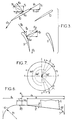
- each blade 10 has a part stream 14 with aerodynamic profile, one blade root 15 arranged in a sleeve, by which the blade 10 is mounted swiveling around its longitudinal axis of change of steps in at least one landing arranged for this purpose in at minus an annular wall of a rotor hub 17, and a part of root 16 which can be twisted and preferably also flexible, which passes through the blade root sleeve 15 and is retained by its end opposite to the sleeve 15 on the hub rotor 17, which is rotated by the shaft motor 12 projecting along the axis X-X of the vein 6 on the body 11 surrounding the rear transmission box.
- a pitch control lever 23 connected by a connecting rod to a freely rotating control plate with the rotor 7 but translatable along the axis of rotation of the rotor 7 by the operation of the pitch control rod to collectively control the change of blade pitch 10.
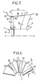
- the vanes 9, fixed in the vein 6 downstream of the blades 10 of the rotor 7, without however leaving the diverging part 21-22 of the vein 6, ensure recovery of the rotational energy of the air flow downstream of the blades 10, by straightening this flow towards the axis XX of the vein 6 and by providing an additional anti-torque thrust, as explained in French patent FR-2,534,222 of the applicant, the description of which is incorporated herein descriptive memory by way of reference, in particular with regard to the description of FIGS. 4 and 5 of this patent, of which FIG. 5 corresponds to FIG. 3 of the present application.
- stator rectifier 8 with 9 fixed blades profiled in downstream of the rotor 7 in the vein 6 makes it possible to produce a compact, balanced and rigid anti-torque device, providing, without modification of the driving power of the rotor 7, an increased anti-torque thrust.
- the acoustic optimization of the device fairing anti-torque is ensured by distributing energy acoustic over the entire frequency spectrum, by adopting an irregular angular distribution of the blades 10 of the rotor 7, called azimuthal modulation or modulation of phase, and by reducing the level of acoustic energy emitted by the anti-torque device, by reducing the peripheral speed of the blades 10 of the rotor 7, by the reduction of interference between the rotor 7, on the one hand, and, on the other hand, the stator rectifier 8 and the arm 13 of transmission, thanks to configuration and layout particular of these elements in vein 6, with a appropriate rotor spacing 7.
- phase modulation phase or azimuthal irregular For a rotor with ten blades 10, an example of modulation phase or azimuthal irregular is represented on the figure 2.
- the purpose of this phase modulation is to break the usual angular symmetry or equal distribution usual angle of the blades of a rotor, so as not to reduce the acoustic energy emitted, but to distribute it more favorably on the frequency spectrum, unlike what is obtained in the absence of modulation (evenly spread blades), namely a concentration of energy on specific frequencies (b ⁇ , 2b ⁇ , 3b ⁇ ).
- nx 360 ° b represents the angular position of the n th blade, in an evenly distributed configuration
- ⁇ ⁇ sin (mxnx 360 ° b ) corresponds to the term of azimuthal modulation compared to the equi-distributed configuration.
- the parameters m and ⁇ ⁇ are chosen as a function of the number b of the blades 10, so as to simultaneously ensure the dynamic balance of the rotor 7, the optimal distribution of energy in the frequency spectrum, and guarantee an angular deviation minimum interpale, imposed by the conditions of deflection of the blades in pitch and of structural resistance of the blades 10 to the hub 17.
- the integer m is as small as possible and preferably set to 2 or 3 in order to obtain a spectrum the densest possible, and therefore better distribution of energy per third of an octave.
- the parameter m can at the must be equal to 4, but the value 1 is to be avoided.
- the parameter ⁇ ⁇ must be chosen as follows: it is greater than or equal to a minimum value ⁇ ⁇ min given by an acoustic criterion for a number of blades 10 of the rotor 7 given, as indicated in table 2 below. b 6 8 9 10 12 ⁇ ⁇ min 14.34 ° 10.75 ° 9.55 ° 8.60 ° 7.17 °
- angular phase shift ⁇ ⁇ b ⁇ ⁇ , which acts as a parameter of the Bessel functions characterizing the levels of the spectral lines of a sinusoidal modulation, with respect to the fundamental line, as explained in the article entitled “Noise Reduction by Applying Modulation Principles” by Donald EWALD et al, published in "The Journal of the Acoustical Society of America", volume 49, Number 5 (part 1) 1971, pages 1381 to 1385.
- phase modulation law based on a degraded sinusoidal law, for which b ⁇ ⁇ can be selected in the value range from 1.5 radian at 1 radian and / or adopt a variation of ⁇ 5 ° around of the angular position, initially given by the law of sinusoidal distribution for each blade 10 of the rotor 7, for cover the constraint of the interpale angular deviation minimal, while maintaining good acoustic efficiency due to phase modulation.
- the anti-torque device includes the rectifier 8, the vanes 9 of which are regularly distributed around the X-X axis of the vein 6, in order to limit the interference between the rotor 7 and the stator rectifier 8, and in particular to avoid any pumping phenomenon (dynamic excitation) between the rotor 7 and the stator 8, the phase modulation of the blades 10 of the rotor 7 is such that any angular difference between two blades 10 of the rotor, not necessarily consecutive, is different from any angular deviation between two vanes 9 of the stator 8, not necessarily consecutive.
- this condition can be translated from the following way: if ⁇ ij represents the angular deviation between the blades of order i and j of the rotor 7, counted successively from any angular origin, i.e. the angle defined between the pitch change axes blades i and j, and if ⁇ k, l represents the angular deviation between the vanes of order k and l of the rectifier 8, then, whatever the values of i, j, k, l, ⁇ i, j is different from ⁇ k, l.
- this condition is considered respected if the differences between the deviations respective angular angles of the different blades 10 of the rotor 7 and of the different vanes 9 of the rectifier 8 are greater than 1 ° in absolute value, for at least half of the vanes 9 of the rectifier 8, without taking account of the transmission arm 13.
- the blades 10 are evenly distributed, just choose a number b of blades 10 of rotor 7 which is first with the number of blades 9 of rectifier 8, so as not to find any angular difference between two blades 10 not necessarily consecutive which is equal to any angular difference between two vanes 9 not necessarily consecutive.
- a reduction in noise pollution due to interactions between rotor 7 and stator rectifier 8 is also achieved by decreasing the energy level acoustics emitted by these interactions, regardless of frequencies on which it is concentrated or distributed.
- the vanes 9 are arranged in a non-radial manner, but each inclined by an angle ⁇ , between approximately 1 ° and about 25 °, in the radial direction, in the opposite direction in the direction of rotation of the blades 10 considering dawn 9 of the center of the vein 6 towards its periphery.
- This direction of tilt not only reduces noise of interaction between the blades 10 of the rotor 7 and the blades 9 stator 8, but also to ensure better recovery of the forces undergone by the rear transmission in the body 11, the vanes 9 working in compression.
- rectifier 8 is to support the rear gearbox and the body 11, the blades 9 can thus best take up the torque of reaction to the torque transmitted to the rotor 7.
- the thickness relative to the aerodynamic profiles of the vanes of the stator 9 8 is chosen so as to reduce the overall dimensions as much as possible in vein 6, while ensuring resistance sufficient mechanics for the body support function 11, and, in practice, the relative thickness of the profiles of the vanes 9 is between about 8% and about 12%.
- the axial spacing between the plane P of rotation of the rotor 7 and the leading edge of the vanes 9 of the rectifier 8, at the periphery of the vein 6, is a distance dr between about 1.3 c and about 2.5 c, where c is the chord of the blades 10 of the rotor 7, chosen in their current part 14, at near the blade root 15, when this cord c is not not constant over the span of the running part 14.
- each blade 9 in addition to the angle ⁇ of inclination on the radial direction, in a plane perpendicular to the X-X axis of the vein 6, and parallel to the plane P of the rotor, each blade 9 is such that its leading edge is distant from a distance dr, ranging from about 1.3 c to about 2.5 c, from the plane P of rotation of the rotor, at the periphery of the vein 6, in preventing the trailing edge of the vanes 9 from entering the outlet delimited by a rounded lip of this vein 6, and each blade 9 is tilted in an arrow by an angle ⁇ in a plane perpendicular to the plane P of the rotor, downstream and towards the periphery of the vein 6, to ensure positioning precise plane P of the rotor by correct positioning of the body 11 and the rear transmission box.
- dr is less than 1.3 c, the sound energy level radiated increases very rapidly when the vanes 9 are close to the plane of rotation P, while if dr is greater than
- the transmission arm 13 is assimilated to a vane 9 of the rectifier 8 for the determination angular positions of the blades 9 and the blades 10, but it is not profiled, and the number of blades 9 profiled is chosen greater than or equal to the number of blades 10 of the rotor 7 minus one.
- blades 10 advantageously have an aerodynamic profile OAF type, with relative thickness and progressive camber depending on the size, the relative thickness decreasing by example from 13.9% to 9.5% between 0.4 R and R, where R is the radius of the rotor 7. Similarly, the twisting of the profile decreases in moving away from the rotor axis.
- the annular wall 18 of the vein 6 comprises, from upstream downstream, an inlet converger 19, a cylindrical part 20, in which the rotor 7 rotates, as indicated by the plane of rotation P, and a frustoconical divergent 21 is ending with a rounded outlet lip 22.
- the vein 6 is subdivides into two parts, including a corresponding collector to the part of the vein located upstream of the plane of rotation P of the rotor 7, and of axial dimension dc (along the axis X-X of the vein 6), and a diffuser, corresponding to the part of vein 6 located downstream of the plane of the rotor P and of dimension axial dd.
- the collector itself divides into two zones: the convergent 19, delimited by an annular wall or lip input convex upstream and rounded with a radius Rc constant, and a cylindrical zone of length L1 which follows.
- the diffuser is divided into three zones, one of which cylindrical zone of length L2, extending the zone cylindrical L1 of the manifold, the frustoconical half-angle zone at the vertex ⁇ of the divergent 21, and the divergent exit delimited by the outlet lip 22, in the form of a wall annular convex downstream and rounded with radius r.
- the ratio L1 / ⁇ must be between approximately 0.02 and approximately 0.08, to avoid that a too large cylindrical zone L1 strongly degrades the performance of the rotor faired.
- the radius Rc of the inlet lip 19 is determined so that its ratio to the diameter of the vein ⁇ is approximately 0.08.
- L1 must be such that: L1> a sin ( ⁇ max) + f , where ⁇ max is the maximum positive step angle. To avoid any overflow of the blade 10 outside and at the front of the cylindrical part 20, an additional margin of 1.33% of ⁇ is taken into account.
- the length L2 of the cylindrical zone of the diffuser varies between 1% and 3.5% of the vein diameter ⁇ . In practice, it is given by the following formula: L2 ⁇ (c - a) sin ( ⁇ max) .
- the angle of diffusion ⁇ (half-angle at the top of the divergent frustoconical 21) is chosen between approximately 5 ° and about 20 °.
- the length df of the divergent part of the diffuser directly depends on the angle of diffusion a and is inversely proportional to the diffusion, defined by a diffusion rate corresponding to the surface area ratio of exit of the vein 6 on the surface of the rotor disc 7, this remaining broadcast ratio greater than 1.06.
- the radius r of the lip convex annular outlet 22 of the diffuser is not constant over the entire periphery of this lip. Areas of evolution of the radius r are shown in Figure 7 schematically showing the outlet of the diffuser in elevation lateral.
- the Y-Y axis is the front axis (towards left) - rear (to the right) or longitudinal of the helicopter passing through the axis X-X of the vein 6, and the axis Z-Z is the vertical axis also intersecting the X-X axis of the vein 6.
- Lip 2 has a small constant radius r1, lower at about 1.6% of the diameter ⁇ of the vein 6, in an area front extending over the arc of circle AA corresponding to a angle at the center of 210 ° and symmetrically with respect to the Y-Y axis.
- the lip 22 has a radius r2> r1 and between approximately 4.3% of the diameter ⁇ of the vein and the radius Rc chosen for the convergent 19, in an area rear extending on the arc BB corresponding to an angle at center of 90 °, symmetrically on either side of the axis YY.
- front and rear zones extend two zones with evolving radius, between r1 and r2, and corresponding to the arcs AB each subtended by an angle at the center of 30 °.
- These areas of evolving radius necessary for constraints of manufacturing, ensure the transition between the front parts and rear of the outlet lip 22.
- the area front of small radius r1 can extend on the arc A'A ' corresponding to an angle at the center of up to 240 °.
- the transition zones corresponding to the arcs A'B are then shorter.
- the device anti-torque is faired in a 750 mm vein 6 of diameter, with a rotor with 8 metal blades having a running part 14 with tail and a monobloc sleeve 15, and as described in US-3,594,097, the diameter of the hub rotor being 304 mm, the chord of the blades 58 mm or 63 mm depending on whether the blade tip speed is 186 m / s or 180 m / s, the pitch range of the blades extending from - 25 ° to + 41 ° at 0.7 R (R is the radius of the rotor), and the profile of the blades being a progressive OAF profile, as mentioned above, with a law twist decreasing from 17 ° to 6.9 ° from 0.4 R to R.
- R is the radius of the rotor
- the inclination ⁇ of the vanes 9 in the radial direction passing through the base of each is of the order of 10 ° and their arrow angle ⁇ towards the periphery and towards the exit of the vein 6 is 4 °.
- the distance dr separating the plane from rotation P of the rotor of the leading edge of the blades 9 is 96.5 mm, i.e. approximately 1.53 times to 1.66 times the string of rotor blades.
- the profiled blades 9 of the rectifier have a NACA 65 type profile with a relative thickness of 10%, a camber of the middle line of the profile of 27 ° and a 2.5 ° pitch setting on the X-X axis of the vein 6.
- This last one has a convergent 19 whose radius Rc is 60 mm, the length L1 of the cylindrical area of the manifold is 24 mm, the length L2 of the cylindrical zone of the diffuser is 23 mm, the angle of divergence ⁇ is 7 °, and the lip outlet 22 has a radius r1 of 10 mm on the front zone and a radius r2 of 45 mm on the rear area, the minimum length of the divergent part of the diffuser df being 187 mm.
- the anti-torque device comprises a rotor with 10 blades of 50 mm of rope, driven at a peripheral speed of 187.66 m / s (3584 rpm) with a hub with a diameter of 380mm, housed in a vein of 1 m in diameter.
- the blade profile is an OAF profile similar to that of the previous example, and the pitch range extends from - 25 ° to + 35 ° (at 0.7 R).
- the rectifier has ten blades profiled with a 97 mm cord, to which is added the transmission arm 13. This leads to the following modulation: not 1 2 3 4 5 ⁇ n 44.9 ° 77.5 ° 102.5 ° 135.1 ° 180 ° not 6 7 8 9 10 ⁇ n 224.9 ° 257.5 ° 282.5 ° 315.1 ° 360 °
- the deflection angle ⁇ of the profiled blades is 4 ° and their inclination ⁇ in the radial direction is 7.8 °.
- the distance dr between the plane P of the rotor and the profiled blades 9 is about 98 mm, or about 1.96 times the chord c of blades.
- the blades of the rectifier 9 have a NACA type profile. 65 to 10% relative thickness, with a camber of 21 ° for the middle line of the profile, and a pitch setting of 2.5 °.
- the radius Rc of the inlet converging vein 6 is 80 mm, and the lengths L1 and L2 are respectively 23 mm and 17 mm for the cylindrical zones respectively of the collector and diffuser.
- the angle of divergence ⁇ is 7 ° and the minimum length df of the divergent part of the vein is 280 mm.
- the radius r1 of the front zone of the lip 22 is 10 mm while its radius r2 over the area rear is 60 mm.
- an example of an anti-torque device may include a rotor of ten blades with a 94 mm rope, driven with a peripheral speed at the end of blade of 180 m / s (3125 rpm) in a vein of 1100 mm in diameter, the radius of the hub being 225 mm.
- the pitch change axis of the blades is 40% of their chord c, and their profile is an evolving OAF profile, with the same law of variation of the relative thickness, but a twist law which decreases from 7.25 ° to - 1.2 ° between 0.4 R and R.
- the rectifier comprises either 13 blades, 12 of which are profiled with an 80 mm cord to which the transmission arm is added, or 17 blades of which 16 profiles with a 66 mm rope and to which is added the transmission arm.
- the profile of the profiled blades is a NACA 65 type profile with 10% relative thickness, a camber of 23 ° and a pitch setting of 2.2 °.
- the angle ⁇ of tilting of the profiled blades is 3 ° and their angle ⁇ of inclination in the radial direction is 11.2 °.
- the distance dr between the plane P of the rotor and the leading edge of the blades is 1.65 c to 1.7 c, and the application of the degraded sinusoidal law mentioned above, to obtain a phase modulation leading that no angle between any two blades is equal to any angle between any two blades, leads to the angular distribution of the 10 blades of the rotor given in table 3 below (see next page), depending on whether the stator rectifier comprises 13 or 17 blades.
- Figure 2 shows the rotor with the distribution angular indicated in table 3 above for a stator rectifier with 13 blades.
Landscapes
- Engineering & Computer Science (AREA)
- Mechanical Engineering (AREA)
- Aviation & Aerospace Engineering (AREA)
- Structures Of Non-Positive Displacement Pumps (AREA)
Claims (11)
- Gegendrehmomentvorrichtung für einen Hubschrauber, die einen mit variablem Anstellwinkel ausgelegten Mehrblatt-Rotor (7), der rotierend und im wesentlichen koaxial in einem Luftströmungskanal (6) mit einer Achse (X-X) angebracht ist, die zum Hubschrauber im wesentlichen quer verläuft und einen in die Heckpartie (1-2) des Hubschraubers integrierten Tragkörper (5) durchquert, so daß sich die Achsen zur Änderung des Anstellwinkels der Blätter (10) in einer zur Achse des stromlinienförmig ausgebildeten Kanals (6) im wesentlichen senkrecht verlaufenden Rotationsebene (P) bewegen, sowie einen Leiteinrichtungs-Stator (8) enthält, der im Kanal (6) strömungsabwärts des Rotors (7) befestigt ist und feststehende Schaufeln (9) aufweist, die im wesentlichen sternförmig um die Achse des Kanals (6) angeordnet sind und jeweils ein unsymmetrisches aerodynamisches Profil aufweisen, wobei die Wölbung und Winkelanstellung in bezug auf die Achse des Kanals (6) so sind, daß die Schaufeln (9) den Luftstrom strömungsabwärts des Rotors (7) im wesentlichen parallel zur Achse des Kanals (6) leiten, dadurch gekennzeichnet, daß die Schaufeln (9) der Leiteinrichtung (8) jeweils gegenüber der radialen Richtung von der Achse des Kanals (6) zu dessen Rand hin geneigt sind und zwar in entgegengesetzter Richtung zum Drehsinn des Rotors (7) und/oder von der Mitte des Kanals (6) zu dessen Rand hin und von der Strömungsaufwärtsseite nach der Strömungsabwärtsseite hin im Kanal (6) gepfeilt schräggestellt sind, und daß der Abstand entsprechend der Achse (X-X) des Kanals (6) zwischen der Rotationsebene (P) des Rotors (7) und der Vorderkante der Schaufeln (9) der Leiteinrichtung (8) am Rande des Kanals (6) eine zwischen 1,3 c und 2,5 c liegende Strecke (dr) ist, wobei c die Tiefe der Blätter (10) des Rotors (7) ist.
- Gegendrehmomentvorrichtung nach Anspruch 1, dadurch gekennzeichnet, daß die Schaufeln (9) der Leiteinrichtung (8) im Kanal (6) einen zum Kanal (6) im wesentlichen koaxialen Körper (11) tragen, der Antriebsorgane des Rotors (7) und Organe zur gemeinsamen Steuerung des Anstellwinkels der Blätter (10) des Rotors (7) enthält, welcher rotierend auf dem Körper (11) angebracht ist.
- Gegendrehmomentvorrichtung nach einem der Ansprüche 1 und 2, dadurch gekennzeichnet, daß ein eine Antriebskraft zum Rotor (7) übertragender Übertragungsarm (13) im Kanal (6) im wesentlichen an der Stelle einer der Schaufeln (9) der Leiteinrichtung (8) angeordnet ist, wobei die profilierten Schaufeln (9) in ihrer Anzahl zumindest gleich mit der um eine Einheit verminderten Anzahl der Blätter (10) des Rotors (7) sind.
- Gegendrehmomentvorrichtung nach einem der Ansprüche 1 bis 3, dadurch gekennzeichnet, daß die Schaufeln (9) der Leiteinrichtung (8) ein aerodynamisches Profil vom Typ NACA 65 mit einem zwischen etwa 8 % und etwa 12 % liegenden Dicke-Tiefenverhältnis, einer zwischen etwa 2 % und etwa 2,5 % liegenden Einstechwinkelanstellung gegenüber der Achse (X-X) des Kanals (6) und einer zwischen etwa 20° und etwa 28° liegenden Wölbung haben.
- Gegendrehmomentvorrichtung nach einem der Ansprüche 1 bis 4, dadurch gekennzeichnet, daß die Blätter (10) des Rotors (7) ein aerodynamisches Profil vom Typ OAF mit einem Dicke-Tiefenverhältnis und einer Wölbung haben, die sich entsprechend der Spannweite entwickeln, wobei sich zwischen 0,4 R und R das Dicke-Tiefenverhältnis von etwa 13,9 % auf etwa 9,5 % verringert und sich die Verwindung von etwa 17° auf etwa 6,9° oder von etwa 7,25° auf etwa -1,2° vermindert, wobei R der Radius des Rotors (7) ist.
- Gegendrehmomentvorrichtung nach einem der Ansprüche 1 bis 5, dadurch gekennzeichnet, daß der Kanal (6) zwei Teile umfaßt, von denen der eine ein Kollektor entsprechend dem strömungsaufwärts der Rotationsebene (P) des Rotors gelegenen Teil des Kanals (6) und der andere ein Diffusor entsprechend dem strömungsahwärts der Rotationsebene (P) gelegenen Teil des Kanals (6) ist, wobei der Kollektor eine Eintrittskonvergenz (19) aufweist, die durch eine konvexe ringförmige Wand strömungsaufwärts hin abgegrenzt und mit einem konstanten Radius (Rc) abgerundet ist, und sich zur Rotationsebene (P) des Rotors hin mit einer zylindrischen Zone von einer ersten Länge (L1) fortsetzt und wobei der Diffusor von der Rotationsebene (P) des Rotors strömungsabwärts hin eine die zylindrische Zone des Kollektors fortsetzende zylindrische Zone von einer zweiten Länge (L2), dann eine kegelstumpfartige Divergenz (21) mit einem halben Kegelwinkel α und einen divergierenden Austritt (22) aufweist, der durch eine konvexe ringförmige Wand strömungsabwärts hin abgegrenzt und mit einem Radius (r) abgerundet ist.
- Gegendrehmomentvorriohtung nach Anspruch 6, dadurch gekennzeichnet, daß die Lage der Rotationsebene (P) des Rotors (7) in dem durch die zylindrischen Zonen des Kollektors und des Diffusors gebildeten zylindrischen Teil (20) des Kanals (6) in Abhängigkeit von der Tiefe (c) der Blätter (10) des Rotors (7), von ihrem Bereich mit positivem Anstellwinkel, vom Abstand (a) zwischen ihrer Vorderkante und der Anstellwinkeländerungsachse und von der maximalen Biegungslinie (f) des Blattes (10), die seine Schlagsteifigkeit charakterisiert, so festgelegt wird, daß die Längen L1 und L2 der zylindrischen Zonen so beschaffen sind, daß:
- Gegendrehmomentvorrichtung nach einem der Ansprüche 6 und 7, dadurch gekennzeichnet, daß die Länge (L1) der zylindrischen Zone des Kollektors zwischen etwa 2 % und etwa 8 % des im zylindrischen Teil (20) gemessenen Durchmessers (⊘) des Kanals (6) liegt, der konstante Radius (Rc) der Eintrittskonvergenz (19) des Kollektors ungefähr 8 % des Durchmessers (⊘) des Kanals (6) beträgt und sich die Länge (L2) der zylindrischen Zone des Diffusors zwischen etwa 1 % und etwa 3,5 % des Durchmessers (⊘) des Kanals (6) bewegt.
- Gegendrehmomentvorrichtung nach einem der Ansprüche 6 bis 8, dadurch gekennzeichnet, daß der Kegelhalbwinkel (α) der kegelstumpfartigen Divergenz (21) zwischen etwa 5 % und etwa 20 % gewählt ist.
- Gegendrehmomentvorrichtung nach einem der Ansprüche 6 bis 9, dadurch gekennzeichnet, daß die ringförmige Wand des divergierenden Austritts (22) des Diffusors einen konstanten ersten Radius (r1) von weniger als etwa 1,6 % des Durchmessers (⊘) des Kanals (6) auf einem sich zum Bug des Hubschraubers hin erstreckenden Kreisbogen (AA), einen konstanten zweiten Radius (r2), der zwischen etwa 4,3 % des Durchmessers (⊘) des Kanals (6) und dem für die Konvergenz (19) des Kollektors gewählten Radius (Rc) liegt, auf einem sich zum Heck des Hubschraubers hin erstreckenden Kreisbogen (BB), und zwei Zonen (AB) mit sich veränderndem Radius (zwischen r1 und r2) hat, welche die Zonen mit konstanten Radien (r1 und r2) symmetrisch beiderseits einer Längsachse (YY) des Hubschraubers verbinden.
- Gegendrehmomentvorrichtung nach Anspruch 10, dadurch gekennzeichnet, daß sich die vordere Zone mit konstantem Radius (r1) auf einem Kreisbogen (AA) entsprechend einem Mittelpunktswinkel von mindestens 210° und die hintere Zone mit konstantem Radius (r2) auf einem Kreisbogen (BB) entsprechend einem Mittelpunktswinkel von 90° erstrecken und zwar symmetrisch oberhalb und unterhalb der erwähnten Längsachse (YY) des Hubschraubers.
Applications Claiming Priority (2)
| Application Number | Priority Date | Filing Date | Title |
|---|---|---|---|
| FR9405479A FR2719551B1 (fr) | 1994-05-04 | 1994-05-04 | Dispositif anti-couple à rotor et stator redresseur carénés, et à aubes redresseuses inclinées. |
| FR9405479 | 1994-05-04 |
Publications (2)
| Publication Number | Publication Date |
|---|---|
| EP0680873A1 EP0680873A1 (de) | 1995-11-08 |
| EP0680873B1 true EP0680873B1 (de) | 1998-04-01 |
Family
ID=9462872
Family Applications (1)
| Application Number | Title | Priority Date | Filing Date |
|---|---|---|---|
| EP95400998A Expired - Lifetime EP0680873B1 (de) | 1994-05-04 | 1995-05-02 | Gegendrehmomentvorrichtung mit einem eingelassenen Heckrotor und Abrichtstator und mit schrägen Richtleitschaufeln |
Country Status (6)
| Country | Link |
|---|---|
| US (1) | US5634611A (de) |
| EP (1) | EP0680873B1 (de) |
| JP (1) | JP3043594B2 (de) |
| CN (1) | CN1062226C (de) |
| DE (1) | DE69501911T2 (de) |
| FR (1) | FR2719551B1 (de) |
Families Citing this family (32)
| Publication number | Priority date | Publication date | Assignee | Title |
|---|---|---|---|---|
| JP3051357B2 (ja) * | 1997-03-26 | 2000-06-12 | 株式会社コミュータヘリコプタ先進技術研究所 | 主ロータトルク補正装置 |
| US7234914B2 (en) * | 2002-11-12 | 2007-06-26 | Continum Dynamics, Inc. | Apparatus and method for enhancing lift produced by an airfoil |
| RU2263609C1 (ru) * | 2004-04-01 | 2005-11-10 | Открытое акционерное общество "Камов" | Устройство компенсации реактивного момента несущего винта вертолета |
| ATE449237T1 (de) | 2004-07-16 | 2009-12-15 | Bell Helicopter Textron Inc | Gegendrehmomentvorrichtung für hubschrauber |
| FR2925208B1 (fr) * | 2007-12-14 | 2016-07-01 | Eurocopter France | Structure absorbante pour l'attenuation de bruits generes notamment par un rotor et carenage comportant une telle structure |
| FR2926786B1 (fr) | 2008-01-30 | 2010-02-19 | Eurocopter France | Procede d'optimisation d'un rotor anti-couple carene a gene acoustique minimale pour un giravion, notamment un helicoptere, et rotor anti-couple carene ainsi obtenu |
| DE102008058029B3 (de) * | 2008-11-18 | 2010-01-07 | Deutsches Zentrum für Luft- und Raumfahrt e.V. | Hubschrauber |
| CA2762246C (en) * | 2009-05-22 | 2015-07-21 | Bell Helicopter Textron Inc. | Rotor blade spacing for vibration attenuation |
| GB2482545B (en) * | 2010-08-06 | 2017-05-03 | Ge Aviat Systems Ltd | Aircraft propellers with composite blades mounted to a single propeller hub |
| US20120099983A1 (en) * | 2010-10-21 | 2012-04-26 | Charles Howard Medlock | Torque Balanced, Lift Rotor Module, Providing Increased Lift, With Few or No Moving Parts |
| FR2968272B1 (fr) * | 2010-12-06 | 2013-07-12 | Eurocopter France | Element de structure ameliore d'un giravion pour diminuer la trainee aerodynamique. |
| FR2987346B1 (fr) * | 2012-02-27 | 2014-08-29 | Eurocopter France | Pale de rotor, rotor, aeronef, et procede |
| EP2671798B1 (de) * | 2012-06-08 | 2015-08-05 | AIRBUS HELICOPTERS DEUTSCHLAND GmbH | Helikopter mit einem Querkanal |
| EP2706009B1 (de) | 2012-09-07 | 2016-04-27 | AIRBUS HELICOPTERS DEUTSCHLAND GmbH | Leitwerk eines Hubschraubers |
| EP2799334B1 (de) * | 2013-04-29 | 2016-09-07 | AIRBUS HELICOPTERS DEUTSCHLAND GmbH | Rotierende Blattanordnung mit aerodynamischem äußeren Toroidspoiler für eine ummantelte rotierende Antriebsanordnung |
| US8882024B1 (en) * | 2013-06-24 | 2014-11-11 | Bell Helicopter Textron Inc. | Rotorcraft anti-torque rotor and rudder system |
| EP2878433B1 (de) * | 2013-11-29 | 2016-04-20 | AIRBUS HELICOPTERS DEUTSCHLAND GmbH | Ummantelte Drehanordnung aus segmentiertem Verbundwerkstoff für Flugzeuge sowie verfahren zu deren Herstellung |
| EP2913270B1 (de) | 2014-02-28 | 2016-02-24 | AIRBUS HELICOPTERS DEUTSCHLAND GmbH | Drehflügler mit mindestens einem hauptrotor und mindestens einem rotor zum drehmomentausgleich |
| EP2913269B1 (de) | 2014-02-28 | 2019-01-16 | AIRBUS HELICOPTERS DEUTSCHLAND GmbH | Drehflügler mit mindestens einem Hauptrotor und mindestens einem Rotor zum Drehmomentausgleich |
| EP2913271A1 (de) | 2014-02-28 | 2015-09-02 | AIRBUS HELICOPTERS DEUTSCHLAND GmbH | Drehflügler mit mindestens einem Hauptrotor und mindestens einem rotor zum Drehmomentausgleich |
| FR3028838B1 (fr) * | 2014-11-20 | 2016-11-18 | Airbus Helicopters | Aeronef a voilure tournante muni d'un rotor arriere non carene comprenant au moins cinq pales |
| CN104743102B (zh) * | 2015-02-05 | 2017-08-25 | 深圳清华大学研究院 | 用于直升机的涵道和涵道组件 |
| CN104648668A (zh) * | 2015-02-05 | 2015-05-27 | 深圳清华大学研究院 | 用于直升机的尾桨组件 |
| US9944388B2 (en) * | 2015-08-27 | 2018-04-17 | Sikorsky Aircraft Corporation | Rotorcraft state control |
| US10570926B2 (en) | 2015-12-03 | 2020-02-25 | The Boeing Company | Variable-geometry ducted fan |
| CN106477036A (zh) * | 2016-11-29 | 2017-03-08 | 四川特飞科技股份有限公司 | 一种矩形组合涵道飞行器及其飞行控制系统和方法 |
| CN106837863A (zh) * | 2017-03-29 | 2017-06-13 | 徐工集团工程机械有限公司 | 空调叶轮、工程车辆用空调以及工程车辆 |
| US10889366B2 (en) | 2018-09-21 | 2021-01-12 | Textron Innovations Inc. | Ducted thrusters |
| JP7269722B2 (ja) * | 2018-12-13 | 2023-05-09 | 三菱重工業株式会社 | モータ一体型流体機械及び垂直離着陸機 |
| US11034440B2 (en) | 2019-03-01 | 2021-06-15 | Textron Innovations Inc. | Tail rotor gearbox support assemblies for helicopters |
| IT201900007935A1 (it) * | 2019-06-04 | 2020-12-04 | R E M Holding S R L | Ventilatore con virola migliorata |
| US11566530B2 (en) * | 2019-11-26 | 2023-01-31 | General Electric Company | Turbomachine nozzle with an airfoil having a circular trailing edge |
Family Cites Families (21)
| Publication number | Priority date | Publication date | Assignee | Title |
|---|---|---|---|---|
| US2962260A (en) * | 1954-12-13 | 1960-11-29 | United Aircraft Corp | Sweep back in blading |
| CH399643A (it) * | 1962-03-09 | 1965-09-30 | A De Jong N V | Ventilateur axial |
| US3270953A (en) * | 1963-05-21 | 1966-09-06 | Jerie Jan | Axial flow compressor, blower or ventilator with reduced noise production |
| US3285502A (en) * | 1965-01-25 | 1966-11-15 | Brookside Corp | Balanced fan construction |
| US3346174A (en) * | 1966-07-05 | 1967-10-10 | Trane Co | Compact axial flow fan |
| FR1531536A (fr) * | 1967-05-22 | 1968-07-05 | Sud Aviation | Hélice ou rotor à pas variable |
| FR1593008A (de) * | 1968-07-11 | 1970-05-25 | ||
| US3883268A (en) * | 1971-11-01 | 1975-05-13 | Gen Electric | Blunted leading edge fan blade for noise reduction |
| US3747343A (en) * | 1972-02-10 | 1973-07-24 | United Aircraft Corp | Low noise prop-fan |
| JPS5524399Y2 (de) * | 1974-09-10 | 1980-06-11 | ||
| SU726358A1 (ru) * | 1978-06-29 | 1980-04-05 | Институт Горной Механики И Технической Кибернетики Им. М.М.Федорова | Направл ющий аппарат осевой турбомашины |
| FR2534222A1 (fr) | 1982-10-06 | 1984-04-13 | Aerospatiale | Agencement de rotor de queue a poussee accrue pour aeronef a voilure tournante et dispositif pour accroitre la poussee d'un tel agencement |
| FR2542695B1 (fr) * | 1983-03-18 | 1985-07-26 | Aerospatiale | Helice multipale a pas variable a pale s en materiaux composites demontables individuellement, procede de fabrication de telles pales et pales ainsi realisees |
| GB2145774A (en) * | 1983-08-31 | 1985-04-03 | Dowty Rotol Ltd | Bladed rotors and ducts associated therewith |
| FR2600036B1 (fr) * | 1986-06-16 | 1988-09-16 | Aerospatiale | Dispositif directionnel et stabilisateur a rotor anti-couple carene et incline et a empennage en " v " dissymetrique, et helicoptere equipe d'un tel dispositif. |
| DE3736141A1 (de) | 1987-10-26 | 1989-05-11 | Deutsche Forsch Luft Raumfahrt | Flugzeugpropeller |
| US5131604A (en) * | 1991-04-11 | 1992-07-21 | United Technologies Corporation | Helicopter antitorque device |
| US5169288A (en) * | 1991-09-06 | 1992-12-08 | General Electric Company | Low noise fan assembly |
| JP2662838B2 (ja) * | 1992-03-24 | 1997-10-15 | 川崎重工業株式会社 | 回転翼航空機の尾部回転翼 |
| US6070506A (en) * | 1998-07-20 | 2000-06-06 | Snap-On Tools Company | Ratchet head electronic torque wrench |
| US20040102749A1 (en) * | 2002-11-21 | 2004-05-27 | Kimberly-Clark Worldwide, Inc. | Absorbent article with low coefficient of friction between materials of differential tensions |
-
1994
- 1994-05-04 FR FR9405479A patent/FR2719551B1/fr not_active Expired - Fee Related
-
1995
- 1995-04-27 JP JP7104303A patent/JP3043594B2/ja not_active Expired - Fee Related
- 1995-05-02 EP EP95400998A patent/EP0680873B1/de not_active Expired - Lifetime
- 1995-05-02 DE DE69501911T patent/DE69501911T2/de not_active Expired - Lifetime
- 1995-05-03 CN CN95105363A patent/CN1062226C/zh not_active Expired - Lifetime
-
1996
- 1996-09-30 US US08/720,469 patent/US5634611A/en not_active Expired - Lifetime
Also Published As
| Publication number | Publication date |
|---|---|
| DE69501911D1 (de) | 1998-05-07 |
| JP3043594B2 (ja) | 2000-05-22 |
| US5634611A (en) | 1997-06-03 |
| EP0680873A1 (de) | 1995-11-08 |
| DE69501911T2 (de) | 1998-11-26 |
| FR2719551B1 (fr) | 1996-07-12 |
| CN1126159A (zh) | 1996-07-10 |
| CN1062226C (zh) | 2001-02-21 |
| JPH08133192A (ja) | 1996-05-28 |
| FR2719551A1 (fr) | 1995-11-10 |
Similar Documents
| Publication | Publication Date | Title |
|---|---|---|
| EP0680872B1 (de) | Gegendrehmomentvorrichtung mit einem eingelassenen Heckrotor und Abrichtstator, und Phasenmodulation der Rotorblattstellung, eines Hubschraubers | |
| EP0680873B1 (de) | Gegendrehmomentvorrichtung mit einem eingelassenen Heckrotor und Abrichtstator und mit schrägen Richtleitschaufeln | |
| EP0680871B1 (de) | Gegendrehmomentvorrichtung mit einem eingelassenen Heckrotor und Phasenmodulation der Rotorblattstellung eines Hubschraubers | |
| EP0901961B1 (de) | Rotorblatt eines Drehflügelflugzeuges mit reduzierten, akustischen Eigenschaften | |
| EP0842846B1 (de) | Rotorblatt eines Drehflügelflugzeuges mit Pfeilblattspitze | |
| EP0107543B1 (de) | Anordnung für Heckrotor mit grösserem Schub für Drehflügelflugzeug | |
| FR3038882A1 (fr) | Aeronef combine muni d'un dispositif anticouple complementaire | |
| EP2962934B1 (de) | Schaufel mit gekrümmter stapellinie für drehflügelflugzeug | |
| EP3184427B1 (de) | Rotorblatt eines luftfahrzeugs mit angepasster geometrie für die akustische verbesserung in der anflugphase und verbesserung der leistungen im schwebe- und vorwärtsflug | |
| EP0298826A1 (de) | Blatt mit gebogener Spitze für ein Drehflügelflugzeug | |
| CA2951069C (fr) | Pale de rotor d'aeronef a geometrie adaptee pour l'amelioration acoustique lors d'un vol d'approche et l'amelioration des performances en vol d'avancement | |
| FR2490586A1 (fr) | Profil de pale pour voilure tournante d'aeronef | |
| FR2493263A1 (fr) | Moyen de propulsion d'aeronef comprenant un rotor propulsif multipales non carene | |
| EP0036825B1 (de) | Hochleistungsblattflügel für einen Hubschrauberrotor | |
| EP2631169B1 (de) | Rotor, Luftfahrzeug und Verfahren | |
| EP3527487B1 (de) | Verfahren zur verbesserung von einem flügel um den negativen anstellwinkel bei strömungsabriss zu erhöhen | |
| EP3527491A1 (de) | Methode zur verbesserung eines rotorblatts zur steigerung seiner negativen auswirkungen des strömungsabrisses | |
| EP0067097A1 (de) | Endausbildung für Hubschrauberblatt | |
| EP0265335B1 (de) | Luftschrauben, insbesondere für Flugzeugvortriebsmittel | |
| FR2793766A1 (fr) | Pale pour voilure tournante d'aeronef | |
| WO2025022062A1 (fr) | Propulseur aeronautique non-caréné pour aéronef | |
| WO2025022061A1 (fr) | Propulseur aeronautique non-caréné pour aéronef | |
| FR2524569A1 (fr) | Helice aerienne inclinee pour bateau ou eolienne | |
| WO2000032289A1 (fr) | Cerf-volant helicoptere autogire dirigeable |
Legal Events
| Date | Code | Title | Description |
|---|---|---|---|
| PUAI | Public reference made under article 153(3) epc to a published international application that has entered the european phase |
Free format text: ORIGINAL CODE: 0009012 |
|
| AK | Designated contracting states |
Kind code of ref document: A1 Designated state(s): DE FR GB IT |
|
| 17P | Request for examination filed |
Effective date: 19960315 |
|
| GRAG | Despatch of communication of intention to grant |
Free format text: ORIGINAL CODE: EPIDOS AGRA |
|
| 17Q | First examination report despatched |
Effective date: 19970729 |
|
| GRAG | Despatch of communication of intention to grant |
Free format text: ORIGINAL CODE: EPIDOS AGRA |
|
| GRAG | Despatch of communication of intention to grant |
Free format text: ORIGINAL CODE: EPIDOS AGRA |
|
| GRAH | Despatch of communication of intention to grant a patent |
Free format text: ORIGINAL CODE: EPIDOS IGRA |
|
| RAP1 | Party data changed (applicant data changed or rights of an application transferred) |
Owner name: EUROCOPTER |
|
| GRAH | Despatch of communication of intention to grant a patent |
Free format text: ORIGINAL CODE: EPIDOS IGRA |
|
| GRAA | (expected) grant |
Free format text: ORIGINAL CODE: 0009210 |
|
| AK | Designated contracting states |
Kind code of ref document: B1 Designated state(s): DE FR GB IT |
|
| GBT | Gb: translation of ep patent filed (gb section 77(6)(a)/1977) |
Effective date: 19980402 |
|
| ITF | It: translation for a ep patent filed | ||
| REF | Corresponds to: |
Ref document number: 69501911 Country of ref document: DE Date of ref document: 19980507 |
|
| PLBE | No opposition filed within time limit |
Free format text: ORIGINAL CODE: 0009261 |
|
| STAA | Information on the status of an ep patent application or granted ep patent |
Free format text: STATUS: NO OPPOSITION FILED WITHIN TIME LIMIT |
|
| 26N | No opposition filed | ||
| REG | Reference to a national code |
Ref country code: GB Ref legal event code: IF02 |
|
| PGFP | Annual fee paid to national office [announced via postgrant information from national office to epo] |
Ref country code: DE Payment date: 20130423 Year of fee payment: 19 Ref country code: GB Payment date: 20130424 Year of fee payment: 19 |
|
| PGFP | Annual fee paid to national office [announced via postgrant information from national office to epo] |
Ref country code: FR Payment date: 20130626 Year of fee payment: 19 |
|
| PGFP | Annual fee paid to national office [announced via postgrant information from national office to epo] |
Ref country code: IT Payment date: 20140428 Year of fee payment: 20 |
|
| REG | Reference to a national code |
Ref country code: DE Ref legal event code: R119 Ref document number: 69501911 Country of ref document: DE |
|
| GBPC | Gb: european patent ceased through non-payment of renewal fee |
Effective date: 20140502 |
|
| REG | Reference to a national code |
Ref country code: DE Ref legal event code: R119 Ref document number: 69501911 Country of ref document: DE Effective date: 20141202 |
|
| REG | Reference to a national code |
Ref country code: FR Ref legal event code: ST Effective date: 20150130 |
|
| PG25 | Lapsed in a contracting state [announced via postgrant information from national office to epo] |
Ref country code: DE Free format text: LAPSE BECAUSE OF NON-PAYMENT OF DUE FEES Effective date: 20141202 |
|
| PG25 | Lapsed in a contracting state [announced via postgrant information from national office to epo] |
Ref country code: FR Free format text: LAPSE BECAUSE OF NON-PAYMENT OF DUE FEES Effective date: 20140602 Ref country code: GB Free format text: LAPSE BECAUSE OF NON-PAYMENT OF DUE FEES Effective date: 20140502 |