EP0680876B1 - Rotor anti-couple caréné à pales flottantes - Google Patents
Rotor anti-couple caréné à pales flottantes Download PDFInfo
- Publication number
- EP0680876B1 EP0680876B1 EP95401001A EP95401001A EP0680876B1 EP 0680876 B1 EP0680876 B1 EP 0680876B1 EP 95401001 A EP95401001 A EP 95401001A EP 95401001 A EP95401001 A EP 95401001A EP 0680876 B1 EP0680876 B1 EP 0680876B1
- Authority
- EP
- European Patent Office
- Prior art keywords
- rotor
- blade
- axis
- pitch
- cuff
- Prior art date
- Legal status (The legal status is an assumption and is not a legal conclusion. Google has not performed a legal analysis and makes no representation as to the accuracy of the status listed.)
- Expired - Lifetime
Links
- 230000000694 effects Effects 0.000 claims description 10
- 230000009471 action Effects 0.000 claims description 5
- 230000008859 change Effects 0.000 claims description 5
- 239000004963 Torlon Substances 0.000 claims description 3
- 229920003997 Torlon® Polymers 0.000 claims description 3
- 239000000463 material Substances 0.000 claims description 3
- 239000004033 plastic Substances 0.000 claims description 3
- 229920003023 plastic Polymers 0.000 claims description 3
- 229910000831 Steel Inorganic materials 0.000 claims description 2
- 239000010959 steel Substances 0.000 claims description 2
- UONOETXJSWQNOL-UHFFFAOYSA-N tungsten carbide Chemical compound [W+]#[C-] UONOETXJSWQNOL-UHFFFAOYSA-N 0.000 claims description 2
- 241000239290 Araneae Species 0.000 claims 3
- 230000001747 exhibiting effect Effects 0.000 claims 3
- 238000006073 displacement reaction Methods 0.000 claims 1
- 210000000707 wrist Anatomy 0.000 claims 1
- 239000011295 pitch Substances 0.000 description 61
- 238000006243 chemical reaction Methods 0.000 description 15
- 230000003068 static effect Effects 0.000 description 13
- 230000001052 transient effect Effects 0.000 description 11
- 230000009467 reduction Effects 0.000 description 8
- 230000000717 retained effect Effects 0.000 description 6
- 230000008901 benefit Effects 0.000 description 5
- 238000009826 distribution Methods 0.000 description 5
- 125000006850 spacer group Chemical group 0.000 description 5
- 241000940835 Pales Species 0.000 description 3
- 206010033546 Pallor Diseases 0.000 description 3
- 238000010009 beating Methods 0.000 description 3
- 229910052751 metal Inorganic materials 0.000 description 3
- 239000002184 metal Substances 0.000 description 3
- 230000002829 reductive effect Effects 0.000 description 3
- WGLPBDUCMAPZCE-UHFFFAOYSA-N Trioxochromium Chemical compound O=[Cr](=O)=O WGLPBDUCMAPZCE-UHFFFAOYSA-N 0.000 description 2
- 229910000423 chromium oxide Inorganic materials 0.000 description 2
- 230000002349 favourable effect Effects 0.000 description 2
- 230000005484 gravity Effects 0.000 description 2
- 210000002414 leg Anatomy 0.000 description 2
- 230000036961 partial effect Effects 0.000 description 2
- 239000004593 Epoxy Substances 0.000 description 1
- 208000002193 Pain Diseases 0.000 description 1
- 239000004809 Teflon Substances 0.000 description 1
- 229920006362 Teflon® Polymers 0.000 description 1
- 238000004026 adhesive bonding Methods 0.000 description 1
- 230000005540 biological transmission Effects 0.000 description 1
- 230000003247 decreasing effect Effects 0.000 description 1
- 238000009434 installation Methods 0.000 description 1
- 229910001234 light alloy Inorganic materials 0.000 description 1
- 230000000670 limiting effect Effects 0.000 description 1
- 238000012423 maintenance Methods 0.000 description 1
- 230000014759 maintenance of location Effects 0.000 description 1
- 238000004519 manufacturing process Methods 0.000 description 1
- 238000000034 method Methods 0.000 description 1
- 230000007935 neutral effect Effects 0.000 description 1
- 238000005457 optimization Methods 0.000 description 1
- 244000045947 parasite Species 0.000 description 1
- 210000004417 patella Anatomy 0.000 description 1
- 230000000449 premovement Effects 0.000 description 1
- 230000001681 protective effect Effects 0.000 description 1
- 238000011084 recovery Methods 0.000 description 1
- 230000002441 reversible effect Effects 0.000 description 1
- 230000035945 sensitivity Effects 0.000 description 1
- 230000035939 shock Effects 0.000 description 1
- 239000010935 stainless steel Substances 0.000 description 1
- 229910001220 stainless steel Inorganic materials 0.000 description 1
- WFKWXMTUELFFGS-UHFFFAOYSA-N tungsten Chemical compound [W] WFKWXMTUELFFGS-UHFFFAOYSA-N 0.000 description 1
- 229910052721 tungsten Inorganic materials 0.000 description 1
- 239000010937 tungsten Substances 0.000 description 1
- 239000002966 varnish Substances 0.000 description 1
- 210000003462 vein Anatomy 0.000 description 1
Images


Classifications
-
- B—PERFORMING OPERATIONS; TRANSPORTING
- B64—AIRCRAFT; AVIATION; COSMONAUTICS
- B64C—AEROPLANES; HELICOPTERS
- B64C27/00—Rotorcraft; Rotors peculiar thereto
- B64C27/82—Rotorcraft; Rotors peculiar thereto characterised by the provision of an auxiliary rotor or fluid-jet device for counter-balancing lifting rotor torque or changing direction of rotorcraft
-
- B—PERFORMING OPERATIONS; TRANSPORTING
- B64—AIRCRAFT; AVIATION; COSMONAUTICS
- B64C—AEROPLANES; HELICOPTERS
- B64C27/00—Rotorcraft; Rotors peculiar thereto
- B64C27/82—Rotorcraft; Rotors peculiar thereto characterised by the provision of an auxiliary rotor or fluid-jet device for counter-balancing lifting rotor torque or changing direction of rotorcraft
- B64C2027/8254—Shrouded tail rotors, e.g. "Fenestron" fans
Definitions
- the invention relates to a multi-blade pitch rotor variable, for a streamlined aircraft anti-torque device with rotary wing, in particular of a helicopter, and on which each blade is mounted floating at rest on the rotor hub.
- control efforts that it is necessary to produce are intended to defeat not only the static moments applied to each blade, for a position not given, but also the moments resulting from transient efforts, which develop when a position of step to another, by an action of the pilot on the spreader.
- the moment of "flat recall” is the moment from the centrifugal force exerted on each blade element of a rotating rotor and having the effect of opposing any variation in the general pitch, and bring the blades back into the rotation plane. It is known that this moment depends on the distribution of the mass inertia of the entire blade (profiled running part and sleeve) around its axis of not. This moment being in particular responsible for the efforts that must be supplied on a rear rotor, it is known to reduce this moment, and therefore reduce control efforts to provide, reduce this inertia mass relative to the pitch axis by the addition of masses compensation, called “Chinese masses", substantially perpendicular to the main axis of inertia of the blade.
- the moment of lift is due to the fact that the hearth of the aerodynamic force applied to a blade is the deviation from the pitch axis.
- the moment of strength centrifugal is due to the fact that the latter is exerted on the pale, whose center of gravity is, on the rope, at a certain distance from the pitch axis, the taper of the blade tending to create a component of the centrifugal force which is normal to the rotor plane and which, combined with this distance, created a moment around the pitch axis.
- the problem underlying the invention is to propose improvements to known rotors of the aforementioned type of so as to reduce the control effort required to maintain and change the pitch of the blades, without compromising the safety, precision and comfort of piloting, and eliminating the servo-control and the hydraulic circuit associated, in order to obtain a lighter rotor, and of a lesser manufacturing and maintenance cost.
- Another object of the invention is to propose a rotor of the aforementioned type, the control forces of which are reduced about 1/10 of what they are on known rotors, the static control force being very low, for ensure good piloting comfort for a pilot maintaining a not, and the transient control effort required to move from one step position to another per action on a spreader pedal, being greater than the static force of order but in a reasonable envelope to ensure the steering stability and good sensitivity, without risk of the phenomenon known as "overshoot", consisting in moving a spreader pedal too large, requiring corrective compensation on the other pedal.
- the rotor according to the invention is characterized in that the ball joint is carried by one of the two elements that are the lever and the lug, and is engaged in an oblong opening of a worn ring by the other of the two elements, with play according to each of large and small axes of the oblong opening, the clearance according to the minor axis, substantially parallel to the axis of the rotor, being less than the play along the major axis, perpendicular to the minor axis and transverse to the axis of the blade, and each bearing surface is mounted in the corresponding bearing of the hub with a clearance allowing the support of the ball joint against the internal side face of the oblong opening on the side of ends of the minor axis but such that the ball joint cannot abut against the internal lateral face of the opening oblong on the side of the ends of the major axis.
- Landing games also allow significant drag travel and flutter without neither overload the blades nor the control chain. This increased travel allows further reduction the values of the reactions at the stages. Indeed, combined with the centrifugal force of the blades, these deflections generate moments which have the advantage of countering the moments generated by lift and drag.
- the isostatic mounting of the invention allows not only to avoid mounting bearings, which pose space and mass problems, at the bearing level rotation of the blade sleeves on the hub, but also to reduce the constraints in the pitch control, which constraints could also be amplified in known rotors, by the fact that the pitch control is carried out using a rigid control plate.
- the control board In effect, in the absence of play and in the presence of fault (deviation position of the blades relative to each other), the control board is constrained. Games with which the patella is received in the oblong opening of the connection of the pitch lever to the control plate of the invention precisely reduce the efforts of a part of friction at the step lever and other apart from the stressing of the control plate.
- the ball joint comes into contact with a point contact sliding against the internal lateral face of the opening corresponding oblong.
- the oblong opening has two opposite parallel dishes at its major axis and symmetrical with respect to its center, and is provided in a ring inserted and fixed in a housing of the element which carries it and retained by a shoulder against an edge of said housing, and on which shoulder are formed two flats parallel to the major axis of the opening oblong.
- the invention proposes to choose the points application of control efforts to determine the sense of reactions to the bearings so as to discharge the two levels.
- the reactions to the bearings resulting control efforts are, according to the invention, of signs opposed to the reactions to the levels due to the resumption of beating moments.
- the sleeve carries the lever not radially outside the spans, towards the axis of the rotor, and projecting towards the leading edge of the blade.
- the sleeve carries the pitch lever radially outside and close to the litter in position radial external with respect to the axis of the rotor, and projecting towards the trailing edge of the blade, or, if, for each blade, the pitch lever, carried by the sleeve between its two spans protrudes towards the leading edge of the blade when it is closer to the internal radial span than from the other span, or on the contrary, projecting towards the edge blade leakage, when closer to range external radial.
- the axis can simultaneously fix at least one distinct Chinese mass to the muff.
- the mass chinese includes a socket, engaging a bore transverse of the sleeve, and integral with a collar, applying against a lateral face of the sleeve, and presenting at minus a key for its positioning on the sleeve, the collar carrying, on the side opposite the sleeve, a counterweight inclined substantially towards the leading edge and towards the top of the upper surface or towards the trailing edge and towards the underside of the lower surface of the blade, depending on whether the mass Chinese is fixed on the side respectively of the upper surface or of the lower surface of the blade, which makes it possible to orient favorably the distribution of the blade inertia around its axis of step so as to obtain a moment of "recall to flat "zero or even negative, in order to reverse the recall flat.
- the multi-blade rotor designated as a whole by 1 in Figure 1, is, in a well known manner, intended to be mounted in a streamlined vein formed transversely in the vertical rear part of a helicopter, as shown in Figure 1 of the two aforementioned patents.
- this rotor comprises ten blades 2, each of which has a running part profile 3, with aerodynamic profile, as well as a blade root 4.
- the latter comprises a sleeve 5 in one piece metallic, light alloy, with profiled part 3, as well as two coaxial ranges 6 and 7, around the axis longitudinal pitch change X-X of the blade, and cylindrical shape, these two ranges 6 and 7 being more spaced from each other along the pitch axis X-X.
- the sleeve 5 is mounted swiveling around of the pitch axis X-X in two coaxial bearings 8 and 9 mounted each in one of two walls 10 and 11 respectively a hub body 13 of a hub marked as a whole in 12.
- This hub 12 is rotated about the axis A-A of the rotor by a rotor shaft 14, mounted in rotation around axis A-A in a rear gearbox marked as a whole by the reference 15, and not described in detail because of a known structure.
- this rear transmission box 15 comprises a gear bevel 16 driven in rotation by a drive shaft 17 connected to an output of the main gearbox of the helicopter, the bevel gear 16 being engaged with a ring gear at the base of the rotor shaft 14.
- the blade 2 is connected to the hub 12 by a part root consisting of a flexible and twistable arm 18 around the pitch axis of the blade.
- this arm twistable 18, capable of retaining blade 2 against force centrifugal which solicits it during rotations of the rotor is consisting of a bundle of stacked metal blades, which are thin, narrow and as long as possible, given the size of the rotor, to have low torsional stiffness.
- the beam of stacked blades of arm 18 is retained at its end external radial with respect to the rotor axis A-A, by an axis floating 19, that is to say with a desired clearance, relative to the sleeve 5, and parallel to the axis of the rotor AA, to avoid additional constraints, by contact between the sleeve 5 and harness 18, in any configuration of the blade, the axis 19 passing through two elongated spacers 20, substantially end to end parallel to the rotor axis A-A, and housed in facing holes in the end of the bundle 18 and in thickened parts of the sleeve 5, forming between them two dishes between which is disposed this external radial end of the arm 18.
- this arm 18 is retained on the hub 12 by an axis 21 parallel to the axis rotor A-A and fixing it between two superimposed central parts a fluted flange 22 and a crown 122 integral in rotation by axial splines of the rotor shaft 14.
- the axes 21 simultaneously ensure the fixing of the fluted flange 22 on the hub body 13, for secure the assembly in rotation around the rotor axis A-A.
- each twistable arm 18 has its radial part external housed in the sleeve 5 of the corresponding blade root 4, by being integral in torsion with the latter around the pitch axis of the blade, while its radial part internal, leaving the sleeve 5, is embedded in the flange grooved 22.
- the sleeve 5 of each of them has a step lever 23, the end of which, off-center with respect to the pitch axis X-X of the blade, supports a bolted pin 24 supporting a ball joint 30 received in an opening 32 of a ring 31 (see Figure 3) carried by a step control tab 25, substantially parallel to the rotor axis A-A, and integral with a plate of control 26 with as many legs 25 as the rotor has blades 2.
- This control plate 26 is integral in rotation of a central control axis 27, passing through coaxially (relative to the rotor axis A-A) the rotor shaft 14 tubular, and mounted axially movable in the latter, the base of the central control axis 27 cooperating, via a ball bearing 28, with a connecting rod step control 29, not rotating, but axially displaced along the rotor axis A-A by the operation of the spreader, without through a servo valve.
- axis 27 and the control plate 26 can be translated along the axis rotor A-A, turning with the hub 12 and the blades 2. This doing so, the control tabs 25 of the plate 26 drive the step levers 23, by means of the ball joints 30 which articulate them to each other, rotating around pitch axes, against the link arms 18, twisted.
- the ball joint 30, mounted on the crank pin 24 fixed to the end of the lever step 23, is received in an oblong opening 32 of the ring 31, fitted from the inside to the outside and fixed, by example by gluing, in a housing of corresponding shape formed in the tab 25 of the control plate 26, in being retained against the edge of the housing by a shoulder 31a projecting externally on the sides corresponding to the ends of the major axis of its oblong opening 32.
- the shoulder 31a has two symmetrical flats 33, parallel to the major axes of the oblong opening 32.
- the ball 30 is received in the oblong opening 32 with both a Jp game along its minor axis and a Jg game along its major axis.
- This superior Jg game along the major axis results from the oblong shape of the opening 32, the internal side wall of which has two zones flat 34 opposite and symmetrical, at the ends of the small axis and parallel to the flats 33 of the ring 31.
- the play Jp in the direction of the beats can be 0.5 mm and the clearance Jg in the direction of the drag of 0.5 mm + 1.2 mm or 1.7 mm, and the ball joint 30 with carbide surface of tungsten is in plane contact with point contact sliding on the internal side face, also made of tungsten carbide, of the oblong opening 32.
- the bearing surfaces 6 and 7 of the sleeve 5 of the foot blades are each mounted in the corresponding bearing 8 or 9 of the hub with a nominal radial clearance of, for example, 0.5 mm, for bearings 8 and 9 with a center distance of 65 mm, greater than the distance between the bearings of the previous achievements, the bearing 6 in the external radial position relative to the rotor axis A-A, having a diameter of 47 mm and the bearing 9, in internal radial position, a diameter of 34 mm, these diameters being reduced compared to those of the bearings of analogous achievements of the state of the art.
- any positive pitch command, or negative, from this initial position does not produce no consequence, at a start of travel of 0.25 mm, for resume play, and with zero control effort.
- each step increase, in absolute value corresponds to a drive of the ball 30 by the ring 31, moved with the control plate 26, this movement of the ball joint 30 being transmitted by the crank pin 24 to the pitch lever 23 which causes the blade to rotate around its pitch axis.
- control effort remains positive, whatever be the pitch variations in this area, and it's not that by going in negative step that the device will change from contact zone 34, after, again, resumption of play Jp along the minor axis, without effect in a maneuvering range around the zero pitch.
- the game Jg more important along the major axis of the oblong opening 32 is such, given the radial clearances at the bearings 8 and 9, that any contact of the ball 30 with the ring 31 in zones 35, on the end side of the large axis, to avoid harmful support reactions which would increase the friction forces at the supports.
- the ball joint 30 can be pressed against a zone 35, there would be an effort on the ball 30 transient directed to the other zone 35 which would give a moment of opposite direction to the moment of step control which one needs, and applied by the control effort on the ball joint 30 and at the end of the pitch lever 23.
- spans 6 and 7 of the sleeve 5 covered with a deposit of chromium oxide and rotating in bearings 8 and 9 made of a plastic material low coefficient of friction such as Torlon (brand filed). Hard chromium oxide deposits, ensuring protective effect, are further covered with a layer of varnish in Teflon Epoxy (registered trademark). We thus obtain a dynamic coefficient of friction of the order of 0.15.
- the pitch lever 23 of each blade 2 is at the times cantilevered relative to spans 6 and 7, radially inside the internal radial surface 7, and projecting from the leading edge of blade 2.
- the position of the pitch lever 23 on the leading edge side a as a consequence that the control effort has the same sign as the aerodynamic thrust stressing the blade.
- the position of the step lever 23 overhanging, outside bearings 8 and 9 and on the center side of the rotor has for advantage that the cantilever loading of the sleeve 5 counteracts the cantilever loading induced by the thrust on the blade.
- the control effort tends to discharge stages 8 and 9, hence a reduction in the transient force control.
- the angular setting of the twisting arm 18 is fixed at 8 °, relative to the direction of the normal to the plane of blade of blade 2 at a point taken at 0.7 R, where R is the radius of the rotor, which corresponds to a particular point on the span of blade 2, including the profile of the part current 3 is arched and twisted.
- the angular setting of the arm twistable 18 is fixed at 3 ° more than the middle of the range total step at 0.7 R to further reduce stiffness in torsion of the beam in the usual range of steps.
- each twistable arm 18 consists of a nominal stacking of 23 coated stainless steel blades possibly an anti-fretting deposit, with a thickness of 0.2 mm and a twistable length of about 85 mm, this value resulting from a compromise between the stiffness of the arm twist 18 and the diameter of the rotor hub.
- twistable arm 18 comprises substantially twice as many blades, each twice thinner than those constituting the metal beams torsible on known anti-torque rotors produced according to patent US-3,594,097.
- Reducing mass inertia around the axis of step, inertia at which the flat recall moment is directly proportional, is obtained by an optimization the distribution of the inertias of the entire blade 2, in its current part 3 as in its blade root 4, and by the addition of Chinese masses.
- Optimizing the distribution of the inertias of the profiled running part 3 was obtained by adopting a setting the pitch axis to around 40% on the rope, from from the leading edge of the blade. This setting appears simultaneously favorable to the centering of the blade, necessary for minimize the moment of centrifugal force, by reduction in the distance between the center of gravity of the blade and the pitch axis.
- each twisting arm 18 is no longer directly integrated into the side member of the part profile 3 of the corresponding blade 2, as described in US-4,626,173, but connected to the sleeve 5 by the axis 19 and the spacers 20, forming floating retaining pin, these spacers 20 form Chinese masses directly installed on the connecting axis.
- these spacers 20 we give these spacers 20 as well as axis 19 as long as possible, taking into account mounting and space requirements. This is apparent in figure 1 and in the left half-section of the figure 2.
- the angular position of the Chinese masses formed by the axis 19 and the spacers 20 is not perfect, since these elements are substantially parallel to the axis A-A of the rotor, while there is an 8 ° pre-setting, with zero torsion of the twisting arm 18, between the axis 19 of retention of this arm 18 in the sleeve 5 and normal to plane of the rope at the point of the span of the blade 2 corresponding to 0.7 R, and which is the point of reference to from which the equivalent mass inertia of the whole blade 2.
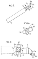
- the blade of Figure 5 is not distinguished from those of rotor of FIGS. 1 and 2 only by its blade root 4a, the sleeve 5a has, in its external radial part directly adjacent to the outer surface 6a, a faceted part flat, forming the dishes between which is retained the outer radial end of the corresponding twisting arm, not shown, using an axis, also not shown, crossing a transverse bore 36 in both sides opposite on the upper and lower sides of the blade.
- the Chinese mass 38 of FIG. 6 includes a cylindrical socket 39, mounted in bore 36, and secured to one end of a collar 40 applying against a corresponding face of the sleeve 5a, and the periphery of which present, on one side intended to be applied against the face internal radial of the external surface 6a, two flats 41 aux ends of a notch and forming keying keys for the establishment of the Chinese mass 38 on the sleeve 5a, as shown in FIG. 7.
- the collar 40 of Chinese mass 38 is a single piece of metal not only with socket 39 but also, on the opposite side, with a massive tongue 42, having the general shape of a relatively thick portion of trunk of cone, forming a curved counterweight and inclined on the axis of the socket 39 and of the central opening of the collar 40, intended to receive the axis of attachment of the Chinese mass 38 to the sleeve 5a, as in the previous example.
- the position of the tongue 42 relative to the keying 41 and its inclination on the axis of the socket 39 are such that, when the mass chinese 38 is mounted on the sleeve 5a (see figure 7), the tongue 42 is inclined towards the leading edge and towards the above the upper surface of the blade, when the mass 38 is fixed on the facet of the sleeve 5a on the side of the upper surface.
- the tongue 42 of the Chinese mass 38 is inclined towards the trailing edge and below the lower surface of the blade, as shown in FIG. 7.
- the sleeve 5a is of preferably equipped with two Chinese masses 38, one at each end of the transverse bore 36 of the sleeve 5a, so that the two tabs 42 ensure distribution favorable mass inertia around an inclined axis in a way to compensate for the angular pre-movement of the arm twist 18.
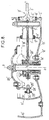
- Figure 8 partially shows in section a another example of a rotor, which will only be described below essential differences compared to that of the figures previous, and whose analogous elements will be identified by the same references assigned a prime symbol.
- each blade 2' is no longer a blade bundle specific to the corresponding blade 2 ', but a radial arm of a star beam, comprising as many arms that the rotor has blades, the center of the star being flat, annular and recessed in 21 'between two flanges central annular radials 22 'of hub 12', bundle in a star thus being analogous to that described in the patent US-3,594,097.
- crank pin 24 'carrying the ball 30' is fixed by screwing on the corresponding tab 25 'of the control plate 26', while the ball 30 ', identical to the ball 30 of the previous example, is received with the necessary games in the oblong opening of a ring 31 ', identical to the ring 31 of the previous example, and mounted in a housing step lever 23 ', also cantilevered inside of the internal surface 7 'of the blade sleeve 5' and in projection from the leading edge of the blade 2 '.
- the 30 'ball joint for example made of steel, is therefore carried by the 25 'control tab, while the ring 31 ', for example in a low coefficient plastic material friction, such as Torlon (registered trademark) is carried by the step lever 23 '.
- Torlon registered trademark
- Rotors are thus produced which it is possible to control with low static control forces and transient, of the order of 1/10 to 1/12 of those necessary in similar embodiments of the state of the art, and using twisted arms whose torque is about 1/8 of that of the previous rotors.
Landscapes
- Engineering & Computer Science (AREA)
- Mechanical Engineering (AREA)
- Aviation & Aerospace Engineering (AREA)
- Structures Of Non-Positive Displacement Pumps (AREA)
- Wind Motors (AREA)
Description
- un arbre rotor, monté en rotation autour d'un axe du rotor,
- un moyeu, solidaire en rotation de l'arbre rotor,
- des pales, dont chacune est reliée au moyeu par une partie d'emplanture comprenant au moins un bras flexible et torsible autour de l'axe longitudinal de changement de pas de la pale, et qui est partiellement logé dans un manchon de pied de pale, le manchon présentant deux portées coaxiales et espacées selon l'axe de la pale, par lesquelles il est monté tourillonnant autour de l'axe de la pale dans deux paliers du moyeu, ainsi qu'un levier de pas, excentré par rapport à l'axe de la pale, et
- un plateau de commande collective du pas des pales, qui est entraíné en rotation avec le moyeu et translatable selon l'axe du rotor par un axe de commande, le plateau présentant, pour chaque pale, une patte de commande de pas, s'étendant sensiblement selon l'axe du rotor, et articulée au levier de pas de la pale correspondante par un maneton à rotule, de sorte que tout déplacement axial du plateau par rapport au moyeu entraíne, par l'action de la patte sur le levier de pas, une rotation de la pale autour de son axe de pas.
- la figure 1 est une vue en perspective avec arrachement et coupes partielles d'un rotor représenté sans ses moyens d'entraínement en rotation ni axe de commande,
- la figure 2 est une coupe diamétrale du rotor avec ses moyens d'entraínement en rotation et de commande de pas, la demi-coupe de gauche correspondant à la figure 1, et la demi-coupe de droite à une variante équipée de pales selon les figures 5 à 7,
- la figure 3 est une vue en élévation latérale d'une bague d'articulation d'un levier de pas sur le plateau de commande du rotor des figures 1 et 2,
- la figure 4 est une coupe selon IV-IV de la figure 3,
- la figure 5 est une vue en perspective d'une variante de pale pour l'équipement du rotor des figures 1 et 2,
- la figure 6 est une vue en perspective d'une variante de masse chinoise pour la pale de la figure 5,
- la figure 7 est une vue en perspective du pied de la pale de la figure 5 équipée de la masse chinoise de la figure 6, et
- la figure 8 est une coupe partielle, analogue à la figure 2, d'une variante de rotor.
Claims (12)
- Rotor multipale à pas variable, pour un dispositif anti-couple caréné d'hélicoptère, et comprenant :un arbre rotor (14), monté en rotation autour d'un axe (A-A) du rotor (1),un moyeu (12), solidaire en rotation de l'arbre rotor (14),des pales (2), dont chacune est reliée au moyeu (12) par une partie d'emplanture comprenant au moins un bras (18) flexible et torsible autour de l'axe longitudinal de changement de pas (X-X) de la pale (2), et qui est partiellement logé dans un manchon (5) de pied de pale (4), le manchon (5) présentant deux portées (6, 7) coaxiales et espacées selon l'axe (X-X) de la pale (2), par lesquelles il est monté tourillonnant autour de l'axe (X-X) de la pale (2) dans deux paliers (8, 9) du moyeu (12), ainsi qu'un levier de pas (23), excentré par rapport à l'axe (X-X) de la pale (2), etun plateau (26) de commande collective du pas des pales (2), qui est entraíné en rotation avec le moyeu (12) et translatable selon l'axe (A-A) du rotor (1) par un axe de commande (27), le plateau (26) présentant, pour chaque pale (2), une patte (25) de commande de pas, s'étendant sensiblement selon l'axe (A-A) du rotor (1), et articulée au levier de pas (23) de la pale (2) correspondante par un maneton (24) à rotule (30), de sorte que tout déplacement axial du plateau (26) par rapport au moyeu (12) entraíne, par l'action de la patte (25) sur le levier de pas (23), une rotation de la pale (2) autour de son axe de pas (X-X),
caractérisé en ce que la rotule (30) est portée par l'un des deux éléments que sont le levier (23) et la patte (25), et est engagée dans une ouverture oblongue (32) d'une bague (31) portée par l'autre des deux éléments, avec du jeu selon chacun des grand et petit axes de l'ouverture oblongue (32), le jeu selon le petit axe, sensiblement parallèle à l'axe (A-A) du rotor (1), étant inférieur au jeu selon le grand axe, perpendiculaire au petit axe et transversal à l'axe (X-X) de la pale (2), et chaque portée (6, 7) du manchon (5) est montée dans le palier (8, 9) correspondant du moyeu (12) avec un jeu permettant l'appui de la rotule (30) contre la face latérale interne de l'ouverture oblongue (32) du côté des extrémités du petit axe mais tel que la rotule (30) ne peut pas venir en appui contre la face latérale interne de l'ouverture oblongue du côté des extrémités du grand axe. - Rotor selon la revendication 1, caractérisé en ce que, pour chaque pale (2), la rotule (30) vient en appui plan à contact ponctuel glissant contre la face latérale interne de l'ouverture oblongue (32) correspondante.
- Rotor selon l'une des revendications 1 et 2, caractérisé en ce que l'ouverture oblongue (32) présente deux plats (34) opposés, parallèles à son grand axe et symétriques par rapport à son centre, et est ménagée dans une bague (31) insérée et fixée dans un logement de l'élément qui la porte et retenue par un épaulement (31a) contre un bord dudit logement, et sur lequel épaulement (31a) sont ménagés deux méplats (33) parallèles au grand axe de l'ouverture oblongue (32).
- Rotor selon l'une quelconque des revendications 1 à 3, caractérisé en ce que, pour chaque pale (2), le manchon (5) porte le levier de pas (23) radialement à l'extérieur des portées (6, 7) vers l'axe (A-A) du rotor (1), et en saillie vers le bord d'attaque de la pale (2).
- Rotor selon l'une quelconque des revendications 1 à 3, caractérisé en ce que, pour chaque pale (2), le manchon (5) porte le levier de pas (23) radialement à l'extérieur et à proximité de la portée (6) en position radiale externe par rapport à l'axe (A-A) du rotor (1), et en saillie vers le bord de fuite de la pale (2).
- Rotor selon l'une quelconque des revendications 1 à 3, caractérisé en ce que, pour chaque pale (2), le levier de pas (23), porté par le manchon (5) entre ses deux portées (6, 7), et plus proche de la portée radiale interne (7) par rapport à l'axe (A-A) du rotor (1) que de l'autre portée (6), est en saillie vers le bord d'attaque de la pale (2).
- Rotor selon l'une quelconque des revendications 1 à 3, caractérisé en ce que, pour chaque pale (2), le levier de pas (23), porté par le manchon (5) entre ses deux portées (6, 7) et plus proche de la portée radiale externe (6) par rapport à l'axe (A-A) du rotor (1) que de l'autre portée (7), est en saillie vers le bord de fuite de la pale (2).
- Rotor selon l'une quelconque des revendications 1 à 7, caractérisé en ce que chaque bras (18) torsible et flexible est lié à la pale (2) correspondante en étant retenu dans le manchon (5), du côté de son extrémité radiale externe par rapport à l'axe (A-A) du rotor (1), par au moins un axe de fixation (19) flottant par rapport au manchon (5) sensiblement parallèlement à l'axe (A-A) du rotor (1) et allongé sensiblement parallèlement à l'axe (A-A) du rotor (1), de façon à procurer un effet de masses chinoises.
- Rotor selon l'une quelconque des revendications 1 à 8, caractérisé en ce que chaque bras (18) torsible et flexible est lié à la pale (2) correspondante en étant retenu dans le manchon (5) du côté de son extrémité radiale externe par rapport à l'axe (A-A) du rotor (1), par au moins un axe de fixation (19) flottant par rapport au manchon (5) sensiblement parallèlement à l'axe (A-A) du rotor (1) et lui-même sensiblement parallèle à l'axe (A-A) du rotor (1) et qui fixe simultanément au moins une masse chinoise (20, 38) au manchon (5).
- Rotor selon la revendication 9, caractérisé en ce qu'au moins une masse chinoise (38) comprend une douille (39), s'engageant dans un alésage (36) transversal du manchon (5'), et solidaire d'un collet (40), s'appliquant contre une face latérale du manchon (5'), et présentant au moins une clef de détrompage (41) pour son positionnement sur le manchon (5'), le collet (40) portant, du côté opposé à la douille (39), un contrepoids (42) incliné sensiblement vers le bord d'attaque et vers le dessus de l'extrados ou vers le bord de fuite et vers le dessous de l'intrados de la pale (2), selon que la masse chinoise (38) est fixée du côté respectivement de l'extrados ou de l'intrados de la pale (2).
- Rotor selon l'une quelconque des revendications 1 à 10, caractérisé en ce que, pour chaque pale (2), la rotule (30) correspondante, portée par le levier de pas (23), et la bague (31) correspondante, portée dans la patte de commande (25), sont en carbure de tungstène ou en tout matériau analogue.
- Rotor selon l'une quelconque des revendications 1 à 10, caractérisé en ce que, pour chaque pale (2'), la rotule (30') correspondante, portée par la patte de commande (25'), est en acier, et la bague (31') correspondante, portée par le levier de pas (23'), est en une matière plastique à faible coefficient de frottement, tel que le Torlon.
Applications Claiming Priority (2)
| Application Number | Priority Date | Filing Date | Title |
|---|---|---|---|
| FR9405482A FR2719554B1 (fr) | 1994-05-04 | 1994-05-04 | Rotor anti-couple caréné à pales flottantes. |
| FR9405482 | 1994-05-04 |
Publications (2)
| Publication Number | Publication Date |
|---|---|
| EP0680876A1 EP0680876A1 (fr) | 1995-11-08 |
| EP0680876B1 true EP0680876B1 (fr) | 1998-04-01 |
Family
ID=9462876
Family Applications (1)
| Application Number | Title | Priority Date | Filing Date |
|---|---|---|---|
| EP95401001A Expired - Lifetime EP0680876B1 (fr) | 1994-05-04 | 1995-05-02 | Rotor anti-couple caréné à pales flottantes |
Country Status (6)
| Country | Link |
|---|---|
| US (1) | US5542818A (fr) |
| EP (1) | EP0680876B1 (fr) |
| JP (1) | JP3209256B2 (fr) |
| CN (1) | CN1062225C (fr) |
| DE (1) | DE69501913T2 (fr) |
| FR (1) | FR2719554B1 (fr) |
Families Citing this family (31)
| Publication number | Priority date | Publication date | Assignee | Title |
|---|---|---|---|---|
| FR2719554B1 (fr) | 1994-05-04 | 1996-07-26 | Eurocopter France | Rotor anti-couple caréné à pales flottantes. |
| US6050778A (en) * | 1998-09-24 | 2000-04-18 | The Boeing Company | Semi-articulated rotor system |
| KR100524340B1 (ko) * | 2001-04-24 | 2005-10-28 | 아사히 가세이 가부시키가이샤 | 자석용 고형 재료 |
| CN100415602C (zh) * | 2005-06-29 | 2008-09-03 | 上海大学 | 非对称桨叶变距装置 |
| FR2893001B1 (fr) * | 2005-11-04 | 2009-04-24 | Eurocopter France | Amelioration aux rotors de giravions a pales torsibles. |
| DE07873274T1 (de) * | 2007-12-03 | 2011-01-27 | Bell Helicopter Textron, Inc., Fort Worth | Mehrblättriges rotorsystem für drehflügler |
| FR2925015B1 (fr) * | 2007-12-14 | 2010-06-04 | Eurocopter France | Pale de giravion, rotor de giravion muni de ladite pale, et procede de fabrication de cette pale |
| US8083482B2 (en) * | 2008-09-30 | 2011-12-27 | Ge Aviation Systems, Llc | Method and system for limiting blade pitch |
| FR2948097B1 (fr) * | 2009-07-15 | 2014-11-21 | Eurocopter France | Rotor d'aeronef muni d'un moyen de retenue de pales |
| GB2472451B (en) * | 2009-08-07 | 2014-06-25 | Christopher Jarvis | Rotor assembly for a rotocraft |
| CN102050219A (zh) * | 2010-12-29 | 2011-05-11 | 广州中船龙穴造船有限公司 | 可变螺距船用螺旋桨 |
| CN102060103A (zh) * | 2010-12-29 | 2011-05-18 | 张东升 | 一种木质螺旋桨及其制作方法 |
| FR2997724B1 (fr) | 2012-11-06 | 2014-11-21 | Snecma | Dispositif de commande du calage des pales, et helice |
| EP2799334B1 (fr) | 2013-04-29 | 2016-09-07 | AIRBUS HELICOPTERS DEUTSCHLAND GmbH | Ensemble rotatif de pale à aileron toroïde extérieur aérodynamique pour un ensemble rotatif de propulsion carénée |
| FR3005301B1 (fr) | 2013-05-03 | 2015-05-29 | Eurocopter France | Rotor carene d'aeronef, et giravion |
| FR3028838B1 (fr) | 2014-11-20 | 2016-11-18 | Airbus Helicopters | Aeronef a voilure tournante muni d'un rotor arriere non carene comprenant au moins cinq pales |
| FR3029170B1 (fr) | 2014-11-28 | 2016-12-30 | Airbus Helicopters | Rotor arriere de giravion, giravion equipe d'un tel rotor arriere et procede d'equilibrage statique et/ou dynamique d'un rotor arriere de giravion |
| KR101579409B1 (ko) * | 2014-12-26 | 2015-12-23 | 남승호 | 프로펠러형 수직 이착륙 비행체의 토크제거 및 균형유지 겸용장치 |
| CN106892103B (zh) * | 2017-01-23 | 2023-06-09 | 南京航空航天大学 | 能电动变距和自动安装拆卸桨叶的直升机旋翼系统及方法 |
| EP3434590B1 (fr) * | 2017-07-27 | 2019-11-27 | AIRBUS HELICOPTERS DEUTSCHLAND GmbH | Élément de transfert de commande pour un dispositif de commande de pas du fenestron d'un giravion |
| KR102344918B1 (ko) * | 2017-08-03 | 2021-12-30 | 삼성전자주식회사 | 프로펠러 장착 구조를 갖는 무인 항공기 |
| EP3953252A1 (fr) | 2019-04-09 | 2022-02-16 | Conseil et Technique | Voilure tournante dans le domaine des aeronefs |
| FR3094954A1 (fr) * | 2019-04-09 | 2020-10-16 | Conseil Et Technique | Voilure tournante dans le domaine des aéronefs |
| EP3753848B1 (fr) * | 2019-06-17 | 2021-08-04 | LEONARDO S.p.A. | Rotor anticouple pour hélicoptère |
| US11433996B2 (en) | 2020-01-20 | 2022-09-06 | Lockheed Martin Corporation | Lightweight low drag rotor pitch beam |
| CH717386A1 (de) | 2020-05-06 | 2021-11-15 | Kopter Group Ag | Lösbare Verbindung zwischen einem Blattsteuereinheitsarm und einem Blattverstellhebel. |
| CH717385A1 (de) * | 2020-05-06 | 2021-11-15 | Kopter Group Ag | Heckrotorkopf eines ummantelten Heckrotors eines Drehflügelflugzeugs und Blatthalterung. |
| US11440651B1 (en) | 2021-03-01 | 2022-09-13 | Textron Innovations Inc. | Spherical bearing centrifugal force retention link |
| FR3122406B1 (fr) | 2021-04-28 | 2023-03-24 | Airbus Helicopters | giravion muni d’un système de contrôle du mouvement en lacet ayant un rotor caréné et une protection contre le givrage |
| CN115560892B (zh) * | 2022-09-20 | 2025-10-03 | 中国航空工业集团公司北京长城计量测试技术研究所 | 一种双向力矩自动化测量装置 |
| FR3160388A1 (fr) * | 2024-03-25 | 2025-09-26 | Airbus Helicopters | Hélice munie de pales et aéronef comportant au moins une hélice |
Family Cites Families (11)
| Publication number | Priority date | Publication date | Assignee | Title |
|---|---|---|---|---|
| FR1531536A (fr) * | 1967-05-22 | 1968-07-05 | Sud Aviation | Hélice ou rotor à pas variable |
| FR1593008A (fr) * | 1968-07-11 | 1970-05-25 | ||
| US4439106A (en) * | 1982-06-14 | 1984-03-27 | United Technologies Corporation | Rotor blade shaft integrity monitoring system |
| FR2542695B1 (fr) * | 1983-03-18 | 1985-07-26 | Aerospatiale | Helice multipale a pas variable a pale s en materiaux composites demontables individuellement, procede de fabrication de telles pales et pales ainsi realisees |
| FR2613319B1 (fr) * | 1987-03-30 | 1989-06-30 | Aerospatiale | Dispositif de palier combine pour rotor de giravion, et rotor equipe d'un tel dispositif de palier |
| IT1240178B (it) * | 1990-04-06 | 1993-11-27 | Agusta Spa | Rotore principale per elicotteri |
| US5297934A (en) * | 1991-08-02 | 1994-03-29 | The Boeing Company | Compensation for kinematic foreshortening effect in pitch control system for rotary wing aircraft |
| CA2113179C (fr) * | 1991-08-02 | 2001-01-23 | Rene A. Desjardins | Rotor de queue carene pour aeronef a voilure tournante assurant la reaction de couple et la commande de direction et d'attitude |
| JP2662838B2 (ja) * | 1992-03-24 | 1997-10-15 | 川崎重工業株式会社 | 回転翼航空機の尾部回転翼 |
| FR2699497B1 (fr) * | 1992-12-23 | 1995-03-10 | Eurocopter France | Dispositif de liaison pale-moyeu à attache feuilletée, pale de rotor munie d'une telle attache, et rotor équipé de telles pales. |
| FR2719554B1 (fr) | 1994-05-04 | 1996-07-26 | Eurocopter France | Rotor anti-couple caréné à pales flottantes. |
-
1994
- 1994-05-04 FR FR9405482A patent/FR2719554B1/fr not_active Expired - Lifetime
- 1994-09-01 US US08/298,317 patent/US5542818A/en not_active Expired - Lifetime
-
1995
- 1995-05-02 DE DE69501913T patent/DE69501913T2/de not_active Expired - Fee Related
- 1995-05-02 EP EP95401001A patent/EP0680876B1/fr not_active Expired - Lifetime
- 1995-05-03 CN CN95105373A patent/CN1062225C/zh not_active Expired - Fee Related
- 1995-05-08 JP JP10980095A patent/JP3209256B2/ja not_active Expired - Fee Related
Also Published As
| Publication number | Publication date |
|---|---|
| EP0680876A1 (fr) | 1995-11-08 |
| DE69501913D1 (de) | 1998-05-07 |
| FR2719554B1 (fr) | 1996-07-26 |
| CN1062225C (zh) | 2001-02-21 |
| FR2719554A1 (fr) | 1995-11-10 |
| JPH08198191A (ja) | 1996-08-06 |
| DE69501913T2 (de) | 1998-12-10 |
| US5542818A (en) | 1996-08-06 |
| JP3209256B2 (ja) | 2001-09-17 |
| CN1126158A (zh) | 1996-07-10 |
Similar Documents
| Publication | Publication Date | Title |
|---|---|---|
| EP0680876A1 (fr) | Rotor anti-couple caréné à pales flottantes | |
| EP0121462B1 (fr) | Hélice multipale à pas variable à pales en matériaux composites démontables individuellement | |
| EP1348623B1 (fr) | Rotor de giravion à entraînement homocinétique avec différentiel de partage de couple | |
| EP0080920B1 (fr) | Rotor pour giravions, à articulations intégrées dans le pied de pale | |
| EP1346910B1 (fr) | Rotor de giravion a entraînement homocinétique | |
| EP0457646B1 (fr) | Dispositif à plateaux cycliques montés sur articulations découplées en tangage et roulis, pour la commande du pas des pales d'un rotor de giravion | |
| EP0162773B1 (fr) | Dispositif à plateaux cycliques montés sur articulations lamifiées pour la commande du pas des pales d'un rotor | |
| EP0213016B1 (fr) | Mât-moyeu intégré et tête de rotor de giravion le comportant | |
| CA2914331C (fr) | Rotor arriere de giravion, giravion equipe d'un tel rotor arriere et procede d'equilibrage statique et/ou dynamique d'un rotor arriere de giravion | |
| FR3005301A1 (fr) | Rotor carene d'aeronef, et giravion | |
| FR2768997A1 (fr) | Dispositif a plateaux cycliques de commande du pas des pales d'un rotor avec piste et doigt d'arret du plateau non tournant | |
| EP1348624B1 (fr) | Dispositif de commande du pas des pales d'un rotor d'aéronef convertible | |
| EP3023328B1 (fr) | Aeronef a voilure tournante muni d'un rotor arriere non carene comprenant au moins cinq pales | |
| EP0549454B1 (fr) | Tête de rotor articulé pour giravion | |
| FR2771708A1 (fr) | Dispositif a plateaux cycliques de commande du pas des pales d'un rotor avec organes guides rotatifs sur coulisseaux translates selon l'axe du rotor | |
| FR2770828A1 (fr) | Dispositif a plateaux cycliques de commande du pas des pales d'un rotor avec plateau non-tournant articule sur une rotule centrale | |
| EP0706936B1 (fr) | Perfectionnements aux dispositifs de commande de pas pour rotors sans articulation | |
| FR2770827A1 (fr) | Dispositif a plateaux cycliques de commande du pas des pales d'un rotor avec plateau non-tournant articule par clavettes sur une rotule centrale | |
| EP0402236B1 (fr) | Dispositif de butées escamotables pour pales de rotors de giravions, et tête de rotor le comportant | |
| WO1998056656A1 (fr) | Rotor de giravion a moyeu bi-plateau et commande de pas partiellement externe | |
| EP0211740A1 (fr) | Mât-moyeu intégré et téte de rotor de giravion le comportant | |
| EP0215688B1 (fr) | Dispositif de butées de battement pour rotor de giravion | |
| EP0718188B1 (fr) | Rotor sans articulation à anneaux intermédiaires de commande de pas | |
| EP0615904B1 (fr) | Tête de rotor pour giravion | |
| BE331615A (fr) |
Legal Events
| Date | Code | Title | Description |
|---|---|---|---|
| PUAI | Public reference made under article 153(3) epc to a published international application that has entered the european phase |
Free format text: ORIGINAL CODE: 0009012 |
|
| AK | Designated contracting states |
Kind code of ref document: A1 Designated state(s): DE GB IT |
|
| 17P | Request for examination filed |
Effective date: 19960315 |
|
| GRAG | Despatch of communication of intention to grant |
Free format text: ORIGINAL CODE: EPIDOS AGRA |
|
| 17Q | First examination report despatched |
Effective date: 19970731 |
|
| GRAG | Despatch of communication of intention to grant |
Free format text: ORIGINAL CODE: EPIDOS AGRA |
|
| GRAH | Despatch of communication of intention to grant a patent |
Free format text: ORIGINAL CODE: EPIDOS IGRA |
|
| RAP1 | Party data changed (applicant data changed or rights of an application transferred) |
Owner name: EUROCOPTER |
|
| GRAH | Despatch of communication of intention to grant a patent |
Free format text: ORIGINAL CODE: EPIDOS IGRA |
|
| GRAA | (expected) grant |
Free format text: ORIGINAL CODE: 0009210 |
|
| AK | Designated contracting states |
Kind code of ref document: B1 Designated state(s): DE GB IT |
|
| GBT | Gb: translation of ep patent filed (gb section 77(6)(a)/1977) |
Effective date: 19980402 |
|
| ITF | It: translation for a ep patent filed | ||
| REF | Corresponds to: |
Ref document number: 69501913 Country of ref document: DE Date of ref document: 19980507 |
|
| PLBE | No opposition filed within time limit |
Free format text: ORIGINAL CODE: 0009261 |
|
| STAA | Information on the status of an ep patent application or granted ep patent |
Free format text: STATUS: NO OPPOSITION FILED WITHIN TIME LIMIT |
|
| 26N | No opposition filed | ||
| REG | Reference to a national code |
Ref country code: GB Ref legal event code: IF02 |
|
| PGFP | Annual fee paid to national office [announced via postgrant information from national office to epo] |
Ref country code: DE Payment date: 20070426 Year of fee payment: 13 |
|
| PG25 | Lapsed in a contracting state [announced via postgrant information from national office to epo] |
Ref country code: DE Free format text: LAPSE BECAUSE OF NON-PAYMENT OF DUE FEES Effective date: 20081202 |
|
| PGFP | Annual fee paid to national office [announced via postgrant information from national office to epo] |
Ref country code: GB Payment date: 20110503 Year of fee payment: 17 |
|
| GBPC | Gb: european patent ceased through non-payment of renewal fee |
Effective date: 20120502 |
|
| PG25 | Lapsed in a contracting state [announced via postgrant information from national office to epo] |
Ref country code: GB Free format text: LAPSE BECAUSE OF NON-PAYMENT OF DUE FEES Effective date: 20120502 |
|
| PGFP | Annual fee paid to national office [announced via postgrant information from national office to epo] |
Ref country code: IT Payment date: 20130423 Year of fee payment: 19 |
|
| PG25 | Lapsed in a contracting state [announced via postgrant information from national office to epo] |
Ref country code: IT Free format text: LAPSE BECAUSE OF NON-PAYMENT OF DUE FEES Effective date: 20140502 |