EP0681120B1 - Régulation du verrouillage de la marche arrière - Google Patents
Régulation du verrouillage de la marche arrière Download PDFInfo
- Publication number
- EP0681120B1 EP0681120B1 EP95302360A EP95302360A EP0681120B1 EP 0681120 B1 EP0681120 B1 EP 0681120B1 EP 95302360 A EP95302360 A EP 95302360A EP 95302360 A EP95302360 A EP 95302360A EP 0681120 B1 EP0681120 B1 EP 0681120B1
- Authority
- EP
- European Patent Office
- Prior art keywords
- reverse
- sensing
- operator
- selection
- output signals
- Prior art date
- Legal status (The legal status is an assumption and is not a legal conclusion. Google has not performed a legal analysis and makes no representation as to the accuracy of the status listed.)
- Expired - Lifetime
Links
- 230000005540 biological transmission Effects 0.000 claims abstract description 51
- 238000000034 method Methods 0.000 claims abstract description 20
- 230000007935 neutral effect Effects 0.000 claims abstract description 15
- 239000000446 fuel Substances 0.000 claims description 8
- 230000009471 action Effects 0.000 claims description 4
- 230000009347 mechanical transmission Effects 0.000 claims description 4
- 238000006073 displacement reaction Methods 0.000 claims 2
- 101100219315 Arabidopsis thaliana CYP83A1 gene Proteins 0.000 abstract 1
- 101100269674 Mus musculus Alyref2 gene Proteins 0.000 abstract 1
- 101100140580 Saccharomyces cerevisiae (strain ATCC 204508 / S288c) REF2 gene Proteins 0.000 abstract 1
- 230000008859 change Effects 0.000 description 4
- 230000007423 decrease Effects 0.000 description 3
- 230000008878 coupling Effects 0.000 description 2
- 238000010168 coupling process Methods 0.000 description 2
- 238000005859 coupling reaction Methods 0.000 description 2
- 230000000717 retained effect Effects 0.000 description 2
- 230000000881 depressing effect Effects 0.000 description 1
- 230000000994 depressogenic effect Effects 0.000 description 1
- 238000001514 detection method Methods 0.000 description 1
- 230000000694 effects Effects 0.000 description 1
- 239000012729 immediate-release (IR) formulation Substances 0.000 description 1
- 230000008569 process Effects 0.000 description 1
- 230000001360 synchronised effect Effects 0.000 description 1
Images



Classifications
-
- B—PERFORMING OPERATIONS; TRANSPORTING
- B60—VEHICLES IN GENERAL
- B60W—CONJOINT CONTROL OF VEHICLE SUB-UNITS OF DIFFERENT TYPE OR DIFFERENT FUNCTION; CONTROL SYSTEMS SPECIALLY ADAPTED FOR HYBRID VEHICLES; ROAD VEHICLE DRIVE CONTROL SYSTEMS FOR PURPOSES NOT RELATED TO THE CONTROL OF A PARTICULAR SUB-UNIT
- B60W40/00—Estimation or calculation of non-directly measurable driving parameters for road vehicle drive control systems not related to the control of a particular sub unit, e.g. by using mathematical models
-
- F—MECHANICAL ENGINEERING; LIGHTING; HEATING; WEAPONS; BLASTING
- F16—ENGINEERING ELEMENTS AND UNITS; GENERAL MEASURES FOR PRODUCING AND MAINTAINING EFFECTIVE FUNCTIONING OF MACHINES OR INSTALLATIONS; THERMAL INSULATION IN GENERAL
- F16H—GEARING
- F16H61/00—Control functions within control units of change-speed- or reversing-gearings for conveying rotary motion ; Control of exclusively fluid gearing, friction gearing, gearings with endless flexible members or other particular types of gearing
- F16H61/16—Inhibiting or initiating shift during unfavourable conditions , e.g. preventing forward-reverse shift at high vehicle speed, preventing engine overspeed
-
- F—MECHANICAL ENGINEERING; LIGHTING; HEATING; WEAPONS; BLASTING
- F16—ENGINEERING ELEMENTS AND UNITS; GENERAL MEASURES FOR PRODUCING AND MAINTAINING EFFECTIVE FUNCTIONING OF MACHINES OR INSTALLATIONS; THERMAL INSULATION IN GENERAL
- F16H—GEARING
- F16H61/00—Control functions within control units of change-speed- or reversing-gearings for conveying rotary motion ; Control of exclusively fluid gearing, friction gearing, gearings with endless flexible members or other particular types of gearing
- F16H61/02—Control functions within control units of change-speed- or reversing-gearings for conveying rotary motion ; Control of exclusively fluid gearing, friction gearing, gearings with endless flexible members or other particular types of gearing characterised by the signals used
- F16H61/0202—Control functions within control units of change-speed- or reversing-gearings for conveying rotary motion ; Control of exclusively fluid gearing, friction gearing, gearings with endless flexible members or other particular types of gearing characterised by the signals used the signals being electric
- F16H61/0204—Control functions within control units of change-speed- or reversing-gearings for conveying rotary motion ; Control of exclusively fluid gearing, friction gearing, gearings with endless flexible members or other particular types of gearing characterised by the signals used the signals being electric for gearshift control, e.g. control functions for performing shifting or generation of shift signal
- F16H61/0246—Control functions within control units of change-speed- or reversing-gearings for conveying rotary motion ; Control of exclusively fluid gearing, friction gearing, gearings with endless flexible members or other particular types of gearing characterised by the signals used the signals being electric for gearshift control, e.g. control functions for performing shifting or generation of shift signal characterised by initiating reverse gearshift
-
- F—MECHANICAL ENGINEERING; LIGHTING; HEATING; WEAPONS; BLASTING
- F16—ENGINEERING ELEMENTS AND UNITS; GENERAL MEASURES FOR PRODUCING AND MAINTAINING EFFECTIVE FUNCTIONING OF MACHINES OR INSTALLATIONS; THERMAL INSULATION IN GENERAL
- F16H—GEARING
- F16H59/00—Control inputs to control units of change-speed- or reversing-gearings for conveying rotary motion
- F16H59/02—Selector apparatus
-
- F—MECHANICAL ENGINEERING; LIGHTING; HEATING; WEAPONS; BLASTING
- F16—ENGINEERING ELEMENTS AND UNITS; GENERAL MEASURES FOR PRODUCING AND MAINTAINING EFFECTIVE FUNCTIONING OF MACHINES OR INSTALLATIONS; THERMAL INSULATION IN GENERAL
- F16H—GEARING
- F16H59/00—Control inputs to control units of change-speed- or reversing-gearings for conveying rotary motion
- F16H59/02—Selector apparatus
- F16H59/0217—Selector apparatus with electric switches or sensors not for gear or range selection, e.g. for controlling auxiliary devices
-
- F—MECHANICAL ENGINEERING; LIGHTING; HEATING; WEAPONS; BLASTING
- F16—ENGINEERING ELEMENTS AND UNITS; GENERAL MEASURES FOR PRODUCING AND MAINTAINING EFFECTIVE FUNCTIONING OF MACHINES OR INSTALLATIONS; THERMAL INSULATION IN GENERAL
- F16H—GEARING
- F16H59/00—Control inputs to control units of change-speed- or reversing-gearings for conveying rotary motion
- F16H59/36—Inputs being a function of speed
- F16H59/44—Inputs being a function of speed dependent on machine speed, e.g. the vehicle speed
-
- F—MECHANICAL ENGINEERING; LIGHTING; HEATING; WEAPONS; BLASTING
- F16—ENGINEERING ELEMENTS AND UNITS; GENERAL MEASURES FOR PRODUCING AND MAINTAINING EFFECTIVE FUNCTIONING OF MACHINES OR INSTALLATIONS; THERMAL INSULATION IN GENERAL
- F16H—GEARING
- F16H59/00—Control inputs to control units of change-speed- or reversing-gearings for conveying rotary motion
- F16H59/50—Inputs being a function of the status of the machine, e.g. position of doors or safety belts
- F16H59/54—Inputs being a function of the status of the machine, e.g. position of doors or safety belts dependent on signals from the brakes, e.g. parking brakes
-
- F—MECHANICAL ENGINEERING; LIGHTING; HEATING; WEAPONS; BLASTING
- F16—ENGINEERING ELEMENTS AND UNITS; GENERAL MEASURES FOR PRODUCING AND MAINTAINING EFFECTIVE FUNCTIONING OF MACHINES OR INSTALLATIONS; THERMAL INSULATION IN GENERAL
- F16H—GEARING
- F16H59/00—Control inputs to control units of change-speed- or reversing-gearings for conveying rotary motion
- F16H59/50—Inputs being a function of the status of the machine, e.g. position of doors or safety belts
- F16H59/56—Inputs being a function of the status of the machine, e.g. position of doors or safety belts dependent on signals from the main clutch
-
- F—MECHANICAL ENGINEERING; LIGHTING; HEATING; WEAPONS; BLASTING
- F16—ENGINEERING ELEMENTS AND UNITS; GENERAL MEASURES FOR PRODUCING AND MAINTAINING EFFECTIVE FUNCTIONING OF MACHINES OR INSTALLATIONS; THERMAL INSULATION IN GENERAL
- F16H—GEARING
- F16H59/00—Control inputs to control units of change-speed- or reversing-gearings for conveying rotary motion
- F16H59/68—Inputs being a function of gearing status
- F16H59/70—Inputs being a function of gearing status dependent on the ratio established
-
- F—MECHANICAL ENGINEERING; LIGHTING; HEATING; WEAPONS; BLASTING
- F16—ENGINEERING ELEMENTS AND UNITS; GENERAL MEASURES FOR PRODUCING AND MAINTAINING EFFECTIVE FUNCTIONING OF MACHINES OR INSTALLATIONS; THERMAL INSULATION IN GENERAL
- F16H—GEARING
- F16H63/00—Control outputs from the control unit to change-speed- or reversing-gearings for conveying rotary motion or to other devices than the final output mechanism
- F16H63/40—Control outputs from the control unit to change-speed- or reversing-gearings for conveying rotary motion or to other devices than the final output mechanism comprising signals other than signals for actuating the final output mechanisms
- F16H63/50—Signals to an engine or motor
- F16H63/502—Signals to an engine or motor for smoothing gear shifts
-
- Y—GENERAL TAGGING OF NEW TECHNOLOGICAL DEVELOPMENTS; GENERAL TAGGING OF CROSS-SECTIONAL TECHNOLOGIES SPANNING OVER SEVERAL SECTIONS OF THE IPC; TECHNICAL SUBJECTS COVERED BY FORMER USPC CROSS-REFERENCE ART COLLECTIONS [XRACs] AND DIGESTS
- Y10—TECHNICAL SUBJECTS COVERED BY FORMER USPC
- Y10T—TECHNICAL SUBJECTS COVERED BY FORMER US CLASSIFICATION
- Y10T74/00—Machine element or mechanism
- Y10T74/19—Gearing
- Y10T74/19219—Interchangeably locked
- Y10T74/19251—Control mechanism
-
- Y—GENERAL TAGGING OF NEW TECHNOLOGICAL DEVELOPMENTS; GENERAL TAGGING OF CROSS-SECTIONAL TECHNOLOGIES SPANNING OVER SEVERAL SECTIONS OF THE IPC; TECHNICAL SUBJECTS COVERED BY FORMER USPC CROSS-REFERENCE ART COLLECTIONS [XRACs] AND DIGESTS
- Y10—TECHNICAL SUBJECTS COVERED BY FORMER USPC
- Y10T—TECHNICAL SUBJECTS COVERED BY FORMER US CLASSIFICATION
- Y10T74/00—Machine element or mechanism
- Y10T74/19—Gearing
- Y10T74/19219—Interchangeably locked
- Y10T74/19251—Control mechanism
- Y10T74/19256—Automatic
- Y10T74/1926—Speed responsive
Definitions
- This invention relates to a control system/method for allowing engagement of the reverse ratio(s) of a vehicular automated transmission only upon the occurrence of a predetermined set of reverse enabling conditions.
- the present invention relates to a control system/method for an automated transmission system having a controller for issuing command output signals to a non-manually controlled transmission actuator which allows/causes issuing of commands for engagement of the transmission reverse ratio(s) only upon sensing the occurrence of a predetermined set of reverse ratio enabling conditions, including at least one condition involving a predetermined continuing action by the vehicle operator, such as continuing to maintain a selector or button in a position against a bias for at least a predetermined period of time and, thus, does not require mechanical interlock devices to reduce the likelihood of accidental or unintentional engagement of a reverse ratio.
- EP-A-0269 942 describes a semi automatic transmission in which the driver is able to select changes of ratio either up or down in steps of one or more ratios. Whether such large steps are permitted is determined by an ECU using a number of sensed parameters such as input and output shaft speeds and vehicle speeds.
- EP-A-0473 298 describes a control method/system corresponding to the preamble of claims 1 and 10, for controlling a shift into neutral of a semi-automated transmission when a torque break occurs and the shifting up or down only if the rate of change of rotational speed of the output shaft is above or below a respective pair of predetermined reference values.
- a vehicular automated transmissions system having a controller for receiving input signals and for processing same according to predetermined logic rules to issue command output signals to non-manually controlled actuators, by providing reverse ratio engagement logic rules by which the controller will issue the commands necessary for driving engagement of the transmission system in a reverse ratio only upon sensing the occurrence of a predetermined set of reverse ratio engagement enabling conditions, including at least one condition involving a predetermined continuing action by the vehicle operator.
- the reverse ratio engagement logic rules may require sensing that (i) the transmission selector has been in the neutral position for at least a first reference period of time (such as one to two seconds), and then (ii) the operator has moved a button or lever to and has retained the button or lever in a predetermined reverse selection position against a bias.
- application of the vehicle brakes may be an additional or alternative precondition for issuing command output signals for driving engagement of the automated transmission reverse ratio(s).
- Figure 1 is a schematic illustration of an automated mechanical change-gear transmission system advantageously incorporating the reverse ratio engagement control of the present invention.
- Figure 2 is a perspective view of the driver's manual shift control and display device.
- Figures 2A and 2B are enlarged views of a portion of the display illustrated in Figure 2.
- Figures 3A and 3B are schematic illustrations of alternative shift selection devices adapted for the present invention.
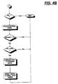
- FIGS 4A, 4B and 4C are schematic illustrations, in flow chart format, of the control system/method of the present invention.
- a vehicular semi-automatic mechanical transmission system 10 is schematically illustrated in Figure 1. While the present invention is illustrated as incorporated into a semi-automated mechanical transmission system, it is understood that the control of the present invention is appicable to various types of fully and partially automated vehicular transmission systems having a controller for receiving input signals indicative of system operating parameters and/or operator requests and for processing same according to predetermined logic rules to issue command output signals to non-manually controllable system actuators.
- a driver-operated throttle 24 is sensed at sensor 22 and fed to a central processing unit 38, which also receives inputs relative to engine speed from sensor 28 and/or transmission input shaft speed from sensor 32, transmission output shaft speed from sensor 36, and positive or negative actuations of the driver's gear shift lever, or "joy stick" 1, to be described in greater detail below.
- transmission output shaft speed is an indication of vehicle ground speed and engine speed is an indication of transmission input shaft speed, and vice versa, especially if clutch 16 is non-slippingly engaged.
- the throttle position sensor 24 may be of the type illustrated in U.S. Patent No. 4,922,425, the disclosure of which is incorporated herein by reference.
- Devices, such as throttle position sensor assembly 22, for sensing the operators setting of a throttle pedal 24 or the like, and providing a signal proportional to or at least indicative of the monitored setting, and so-called "remote fuel control" or "fly-by-wire" systems utilizing same, are known in the prior art and illustrated in U.S. Patents No. 4,250,845; 4,305,359; 4,319,658 and 4,461,254.
- Control logic circuits, sensors and actuators for the transmission system 10 may be as disclosed in above-mentioned U.S. Patents No. 4,361,060; 4,648,290 (corresponding to EP-A-0 269 942); 4,930,081 and 4,930,078.
- central processing unit 38 receives inputs, processes same in accordance with predetermined logic rules, and provides command output signals to pneumatic and/or electrical actuators for control of an exhaust brake 17 and/or an input shaft brake 18 for rapid upshifts, and automatic fuel control 26 to control the supply of fuel to the engine 14 to achieve rapid synchronous rotation preparatory to a shift, clutch control via operator 30, and ratio shifting via transmission operator 34.
- the transmission operator 34 may also be of the "X-Y" type, as illustrated in U.S. Patents No. 4,873,881 and 4,899,607.
- Engine 14 may be electronically controlled, may include a dedicated controller 14A, and may communicate with ECU 38 by means of an electronic data link conforming to a protocol such as ISO 11898, SAE J1922, SAE J1939 or the like.
- clutch pedal 3 is illustrated for use in start-from-stop and low-speed maneuvering, the present invention also is applicable to systems having fully automated master clutches and/or torque converters or other non-positive couplings.
- the central processing unit also sends command output signals to the display 2, to be described in greater detail below.
- the semi-automatic transmission system 10 may additionally comprise a usual foot-operated manual clutch control 3 intended for use only for start-from-rest and/or low-speed creeping maneuvering situations.
- the control 38 receives signals indicative of manual clutch control 3 position and of actuation of the vehicle brakes 4.
- the semi-automatic mechanical transmission system 10 also includes sources of electric and/or pneumatic power (not illustrated).
- the central processing unit may be of the type illustrated in U.S. Patent No. 4,595,986 and may incorporate fault detection and tolerance logic of the type illustrated in U.S. Patents No. 4,849,899; 4,899,279 and 4,945,484.
- blip designates a temporary increase in the supply of fuel to the engine 14, while the term “dip” means a momentary decrease in supply of fuel to the engine.
- dip means a momentary decrease in supply of fuel to the engine.
- the terms blip and dip are usually associated with automatic controller 38 commanded increases and decreases, respectively, of the supply of fuel to the engine independent of the operator selected position of manual throttle pedal 24.
- the central processing unit 38 may be contained in a box or housing 38A, which housing carries the display panel 2 having an upshift indicator display 2', a downshift indicator display 2'', and a currently engaged gear ratio display 2′′′, the shift select lever 1, an optional reverse enable button 1A, as well as a central processing unit electronic circuitry 38B.
- the display 2 includes upshift indicator section 2', downshift indicator section 2'' and currently engaged gear ratio indicator section 2′′′.
- the currently engaged gear ratio display section 2′′′ is presently displaying a "6," indicating that the vehicle transmission is operating in sixth gear.
- the upshift display section 2' has three lines indicating the maximum number of permissible consecutive upshifts permitted according to the sensed input parameters, such as sensed engine or input shaft speed and sensed output shaft speed as processed according to the predetermined logic rules or program. In the present situation, the three lines indicate that a single, double or triple upshift is permissible. Accordingly, the driver may select a permissible shift directly to either seventh, eighth or ninth speed.
- the downshift display 2'' section has two lines indicating the maximum number of permissible consecutive downshifts permitted according to the sensed parameters as processed by the predetermined logic or program. In the present situation, the two lines in display 2' indicate that the transmission may be permissibly downshifted to either fifth or to fourth gear.
- Figure 2B illustrates an alternate display utilizing up/down arrows.
- the permissibility of a possible upshift or downshift is determined by comparing the expected engine speed at the completion of such an upshift or downshift, assuming a substantially constant vehicle speed or a calculated expected vehicle speed and fully engaged master clutch, to a fixed range of maximum and minimum permissible engine speeds.
- the central processing unit 38 will not issue command signals to execute a selected impermissible ratio change.
- a central processing unit will execute the closest permissible ratio change to that selected by the operator.
- the central processing unit 38 will not be executed by the central processing unit 38 as being impermissible.
- the central processing unit 38 will issue command output signals for a double downshift from sixth gear to fourth gear. Not only is an impermissible ratio change refused, but usually, the driver already will have been advised by display 2 that the ratio should never have been attempted or selected.
- the display 2 provides an indication to the operator what upshifts and downshifts are permissible and as to which upshifts and downshifts are impermissible. Should the driver not heed the warning, the central processing unit 38 will not generate impermissible shift command, even though synchronization of the mechanical jaw clutch elements could be obtained by the system.
- the declutching of the master clutch 16 and synchronizing of the selected jaw clutch members associated with the selected gear ratio is achieved automatically and rapidly due to automatic throttle and clutch control and braking of the input shaft and/or the engine.
- the control system is semi-automatic and the driver must exercise discretion as to when to up- or downshift, and as to how many gear ratios to up- or downshift, but is not called upon to coordinate gear lever, throttle pedal and clutch actuation.
- the throttle is blipped to achieve necessary synchronization during a downshift, or dipped for achieving necessary synchronization during an upshift, all of which is done automatically for the driver by the central processing unit 38.
- the reverse mode of operation may be selected only from the neutral, at-rest position and then is selected by moving control lever 1 backwardly from the currently engaged neutral position.
- a reverse button 1A may be provided, which button must be depressed prior to the central processing unit's interpreting a backward movement of the control lever 1 when in the neutral position as a request for reverse operation.
- any type of toggle switch or button which may be located on the end of the shift lever may be utilized in place of reverse enagle button 1A.
- a single control lever of the "P-R-N-D-L" type movable forward and backward in a given direction to select a forward and reverse mode of operation, and then movable in a transverse direction to select upshifts and downshifts either single or multiple, of the type disclosed in U.S. Patent No. 4,442,730 may be substituted for the control lever 1, illustrated.
- the selector lever 1 also may be replaced by any other type of selection device having a non-displaced position and two distinct displaced positions, such as a rocker switch or the like.
- a single movement or pulse of the lever is a movement of the lever from the centered position to a displaced position, in either the upshift or downshift direction, and then the immediate release of the lever, allowing the lever to return to the centered position thereof. If the control lever 1 is retained in the displaced position for more than a predetermined period of time (for example, for more than one or two seconds), an alternate control logic may be utilized.
- the controller 38 will not issue the commands required to drivingly engage a reverse ratio until the occurrence of a predetermined set of reverse ratio engagement enabling conditions is sensed.
- drivingly engaged is intended to mean engagement of a transmission ratio and the coupling(s), 16, drivingly interposed between the engine and the vehicle drive wheels (not shown).
- the predetermined reverse ratio engagement enabling conditions may comprise, for example (i) that the vehicle be at or near rest ( i.e. , OS ⁇ REF 1 ), (ii) that the transmission be allowed to remain in neutral for a period of time (T N ⁇ REF 2 ), such as, for example, about one to two seconds, prior to selection of reverse, (iii) selection of reverse and then (iv) the operator presses the reverse button 1A, or retain the lever 1 in the downshift position for at least a period of time (T R ⁇ REF 3 ), such as, for example, about one to two seconds.
- the application of vehicle brakes at the time of selecting reverse and/or for a period of time thereafter may be required.
- reverse button 1A may be located on selector 1, such as in the knob thereof.
- the selector lever 100 is provided with a knob 102 having a button 104 thereon.
- one of the reverse enabling conditions may comprise depressing button 104 for a predetermined period of time.
- a gated "RE" or reverse enabling slot 108 is provided with a spring-biased plunger/ sensor 110 for resisting entry of the selector lever into the slot.
- the reverse enabling conditions for an automatic transmission system using shift pattern 106 will include causing the selector lever to remain in slot 108 against the bias of plunger 110 for greater than a reference period of time.
- controller 38 may be provided with one or more timer devices or may determine time periods by counting cycles or using other known techniques.
- FIG. 4A and 4B Two embodiments of the reverse ratio engagement control of the present invention are schematically illustrated, in flow chart format, in Figures 4A and 4B and in Figures 4A and 4C.
- Figures 4A and 4B application of the vehicle brakes is shown as a possible additional precondition for enabling engagement of transmission reverse ratio.
- application of the brakes is the operator-initiated enabling signal.
- a reverse ratio engagement control is provided for automated vehicular transmissions which reduces the likelihood of accidental engagement of a reverse ratio requiring a mechanical interlock.
- the control of the present invention may be utilized in connection with a mechanical interlock.
Landscapes
- Engineering & Computer Science (AREA)
- General Engineering & Computer Science (AREA)
- Mechanical Engineering (AREA)
- Physics & Mathematics (AREA)
- Automation & Control Theory (AREA)
- Mathematical Physics (AREA)
- Transportation (AREA)
- Control Of Transmission Device (AREA)
- Structure Of Transmissions (AREA)
- Gear-Shifting Mechanisms (AREA)
Claims (18)
- Méthode pour commander l'engagement d'un rapport de marche arrière dans un système de transmission à changement de vitesse automatisé (10) comprenant un moteur commandé par son débit de carburant (14), une boíte de transmission multirapport (12) ayant plusieurs rapports de marche avant et au moins un rapport de marche arrière, un sélecteur manuel de changement de rapport pour sélectionner les modes d'utilisation de la transmission (1) "marche avant", "point mort" et "marche arrière", une unité de traitement centralisé (38) pour détecter l'utilisation dudit sélecteur manuel de changement de rapport et recevoir des signaux d'entrée et pour traiter ceux-ci selon des règles logiques prédéterminées afin d'envoyer des signaux de sortie de commande à des organes de commande non manuels, dont une commande de boíte de transmission (34), ladite méthode comprenant l'envoi de signaux de sortie de commande pour mettre en prise un rapport de marche arrière seulement en cas (i) de détection d'un maintien dudit sélecteur de changement de rapport sur la position de sélection point mort pendant au moins une durée de référence (NT > REF2) suivie d'une sélection de marche arrière par l'utilisateur et (ii) de détection d'un signal de validation de rapport de marche arrière lancé par l'opérateur, ladite méthode étant caractérisée par
l'envoi desdits signaux de sortie de commande seulement en cas de détection du maintien dudit signal de validation de rapport de marche arrière lancé par l'opérateur par une action continue de celui-ci pendant au moins une durée de référence (RET > REF3) après sélection de la marche arrière. - Méthode selon la revendication 1, caractérisée en ce
que lesdits signaux de sortie de commande pour mettre en prise la marche arrière sont envoyés seulement en cas de détection d'un signal d'entrée représentatif de la vitesse véhicule inférieur à la valeur d'un signal de référence vitesse sol (OS < REF1). - Méthode selon la revendication 1 ou 2, caractérisée en ce
que lesdits signaux de sortie de commande pour provoquer la mise en prise d'un rapport de marche arrière sont envoyés seulement en cas de détection d'un signal d'entrée représentatif du serrage des freins du véhicule après sélection de la marche arrière. - Méthode selon la revendication 1 ou 2, caractérisée en ce
que lesdits signaux de validation de rapport de marche arrière lancé par l'opérateur sont produits par le positionnement, par l'opérateur, d'un dispositif de sélection sur une position prédéterminée en s'opposant à une précontrainte. - Méthode selon la revendication 4, caractérisée en ce
que ledit dispositif de sélection est ledit sélecteur de changement de rapport. - Méthode selon la revendication 4, caractérisée en ceque ledit sélecteur de changement de rapport est précontraint sur une position "non déplacé", est déplaçable dans un premier sens pour sélectionner des montées de rapport et dans un second sens pour sélectionner des descentes de rapport, permet de sélectionner un rapport de marche arrière par déplacement dans ledit second sens lorsque la boíte de vitesses est au point mort, etque ledit signal de validation est produit par maintien dudit sélecteur de changement de rapport déplacé dans le second sens.
- Méthode selon la revendication 1 ou 2, caractérisée en ce
que ladite durée de référence (REF2) est d'environ 1,0 à 2,0 secondes. - Méthode selon la revendication 1, caractérisée en ce
que ladite durée de validation de référence (REF3) est d'environ 1,0 à 2,0 secondes. - Méthode selon la revendication 1 ou 2, caractérisée en ce
que ladite transmission comprend un embrayage principal (16) et une commande manuelle d'embrayage (3) et où lesdits signaux de sortie de commande pour engager un rapport de marche arrière sont envoyés seulement en cas de détections simultanées d'un désengagement manuel dudit embrayage principal et d'une sélection de marche arrière. - Système de commande pour commander l'engagement d'un rapport de marche arrière dans un système de transmission à changement de rapport automatisé (10) comprenant un moteur commandé par son débit carburant (14), une boíte de transmission mécanique multirapport (12) ayant plusieurs rapports de marche avant et au moins un rapport de marche arrière, un sélecteur manuel de changement de rapport pour sélectionner les modes d'utilisation de boíte de transmission (1) "marche avant", "point mort" et "marche arrière", une unité de traitement centralisé (38) pour détecter l'utilisation dudit sélecteur manuel de changement de rapport et recevoir des signaux d'entrée et pour traiter ceux-ci selon des règles logiques prédéterminées afin d'envoyer des signaux de sortie de commande à des organes de commande non manuels, dont une commande de boíte de transmission (34), ledit système de commande comprenant des règles logiques pour délivrer des signaux de sortie de commande pour mettre en prise un rapport de marche arrière seulement en cas (i) de détection d'un maintien dudit sélecteur de changement de rapport sur la position de sélection point mort pendant au moins une durée de référence (NT > REF2) suivie d'une sélection de marche arrière par l'opérateur et (ii) de détection d'un signal de validation de rapport de marche arrière lancé par l'opérateur, ledit système de commande étant caractérisé par
l'inclusion de règles logiques pour envoyer lesdits signaux de sortie de commande seulement en cas de détection du maintien dudit signal de validation de rapport de marche arrière lancé par l'opérateur par une action continue de celui-ci pendant au moins une durée de référence (RET > REF3) après sélection de la marche arrière. - Système de commande selon la revendication 10, caractérisé en ce
que lesdits signaux de sortie de commande pour mettre en prise la marche arrière sont envoyés seulement en cas de détection d'un signal d'entrée représentatif de la vitesse véhicule inférieur à la valeur d'un signal de référence vitesse sol (OS < REF1). - Système de commande selon la revendication 10 ou 11, caractérisé en ce
que lesdits signaux de sortie de commande pour provoquer la mise en prise d'un rapport de marche arrière sont envoyés seulement en cas de détection d'un signal d'entrée représentatif du serrage des freins du véhicule après sélection de la marche arrière. - Système de commande selon la revendication 10, caractérisé en ce
que lesdits signaux de validation de rapport de marche arrière lancés par l'opérateur sont produits par le positionnement, par l'opérateur, d'un dispositif de sélection sur une position prédéterminée en s'opposant à une précontrainte. - Système de commande selon la revendication 13, caractérisé en ce
que ledit dispositif de sélection est ledit sélecteur de changement de rapport. - Système de commande selon la revendication 13, caractérisé en ce
que ledit sélecteur de changement de rapport est précontraint sur une position "non déplacé", est déplaçable dans un premier sens pour sélectionner des montées de rapport et dans un second sens pour sélectionner des descentes de rapport, permet de sélectionner un rapport de marche arrière par déplacement dans ledit second sens lorsque la boíte de transmission est au point mort ; et que ledit signal de validation est produit par maintien dudit sélecteur de changement de rapport déplacé dans le second sens. - Système de commande selon la revendication 10 ou 11, caractérisé en ce
que ladite durée de référence (REF2) est d'environ 1,0 à 2,0 secondes. - Système de commande selon la revendication 10, caractérisé en ce
que ladite durée de validation de référence (REF3) est d'environ 1,0 à 2,0 secondes. - Système de commande selon la revendication 10 ou 11, caractérisé en ce
que ladite transmission comprend un embrayage principal (16) et une commande manuelle d'embrayage (3) et où lesdites règles comprennent des règles destinées à envoyer lesdits signaux de sortie de commande pour engager un rapport de marche arrière seulement en cas de détections simultanées d'un désengagement manuel dudit embrayage principal et d'une sélection de marche arrière.
Applications Claiming Priority (4)
| Application Number | Priority Date | Filing Date | Title |
|---|---|---|---|
| GB9408883 | 1994-05-05 | ||
| GB9408883A GB9408883D0 (en) | 1994-05-05 | 1994-05-05 | Reverse gear ratio engagement |
| GB9502207 | 1995-02-03 | ||
| GBGB9502207.5A GB9502207D0 (en) | 1995-02-03 | 1995-02-03 | Reverse gear ratio engagement |
Publications (2)
| Publication Number | Publication Date |
|---|---|
| EP0681120A1 EP0681120A1 (fr) | 1995-11-08 |
| EP0681120B1 true EP0681120B1 (fr) | 1999-03-03 |
Family
ID=26304827
Family Applications (1)
| Application Number | Title | Priority Date | Filing Date |
|---|---|---|---|
| EP95302360A Expired - Lifetime EP0681120B1 (fr) | 1994-05-05 | 1995-04-10 | Régulation du verrouillage de la marche arrière |
Country Status (8)
| Country | Link |
|---|---|
| US (1) | US5828974A (fr) |
| EP (1) | EP0681120B1 (fr) |
| JP (1) | JPH07301328A (fr) |
| KR (1) | KR950031632A (fr) |
| AT (1) | ATE177174T1 (fr) |
| CA (1) | CA2147289C (fr) |
| DE (1) | DE69507983T2 (fr) |
| ES (1) | ES2129755T3 (fr) |
Families Citing this family (12)
| Publication number | Priority date | Publication date | Assignee | Title |
|---|---|---|---|---|
| KR970046554A (ko) * | 1995-12-29 | 1997-07-26 | 전성원 | 인히비터 스위치신호 제어방법 |
| GB9721823D0 (en) * | 1997-10-16 | 1997-12-17 | Eaton Corp | Shift into optimal engine braking control system and method |
| DE19852292A1 (de) * | 1998-11-12 | 2000-05-18 | Bayerische Motoren Werke Ag | Verfahren beim Anwählen einer Gangstufe bei einem Automatikgetriebe |
| US20040173431A1 (en) * | 2003-03-06 | 2004-09-09 | Devore James Henry | Vehicle brake pedal interlock for heavy vehicle neutral to engaged gear shift |
| KR100507202B1 (ko) * | 2003-07-10 | 2005-08-10 | 현대자동차주식회사 | 자동변속기의 제어방법 |
| JP4616625B2 (ja) * | 2004-11-30 | 2011-01-19 | アイシン・エーアイ株式会社 | 自動変速制御装置 |
| JP4848743B2 (ja) * | 2005-11-17 | 2011-12-28 | トヨタ自動車株式会社 | 自動変速機の制御装置 |
| US20070293367A1 (en) * | 2006-06-16 | 2007-12-20 | Christopher Charles Trevino | Shifting system for a vehicle transmission |
| US8246518B2 (en) * | 2006-06-16 | 2012-08-21 | American Supercars and Prototypes | Shifting system for a vehicle transmission |
| US9828080B1 (en) * | 2016-01-11 | 2017-11-28 | Brunswick Corporation | Lockout for remote controls on marine vessels |
| US10155577B1 (en) * | 2017-07-28 | 2018-12-18 | Brunswick Corporation | Method and system for controlling a marine drive during panic shift |
| US10155578B1 (en) | 2017-08-16 | 2018-12-18 | Brunswick Corporation | Method and system for controlling a marine drive during shift sensor fault |
Family Cites Families (25)
| Publication number | Priority date | Publication date | Assignee | Title |
|---|---|---|---|---|
| US4361060A (en) * | 1978-01-24 | 1982-11-30 | Smyth Robert Ralston | Mechanical automatic transmission |
| US4442730A (en) * | 1981-08-31 | 1984-04-17 | Twin Disc, Incorporated | Vehicle transmission system and a single lever control device therefor |
| US4438666A (en) * | 1981-12-16 | 1984-03-27 | Eaton Corporation | Speed responsive reverse control |
| US4430911A (en) * | 1981-12-16 | 1984-02-14 | Eaton Corporation | Forward-reverse powershift control |
| US4476748A (en) * | 1981-12-16 | 1984-10-16 | Eaton Corporation | Preselect shift control |
| US4608873A (en) * | 1983-04-27 | 1986-09-02 | Clark Equipment Company | Elective automatic shift transmission |
| GB8418749D0 (en) * | 1984-07-23 | 1984-08-30 | Eaton Ltd | Semi-automatic transmission control |
| US4595986A (en) * | 1984-10-09 | 1986-06-17 | Eaton Corporation | Method for control of automatic mechanical transmission system utilizing a microprocessor based electronic controller |
| US4855913A (en) * | 1987-05-29 | 1989-08-08 | J. I. Case Company | Electronic control system for powershift transmission |
| JPH0650258Y2 (ja) * | 1988-01-29 | 1994-12-21 | 株式会社小松製作所 | 車両の自動変速装置 |
| JPH0611219Y2 (ja) * | 1988-12-22 | 1994-03-23 | トヨタ自動車株式会社 | 車両の自動変速機用シフトレバー装置 |
| EP0709602B1 (fr) * | 1989-12-01 | 1999-08-04 | New Holland U.K. Limited | Méthode d'étalonnage pour embrayages de transmission |
| GB9006091D0 (en) * | 1990-03-17 | 1990-05-16 | Eaton Corp | Transducer fault test logic |
| US5089962A (en) * | 1990-08-17 | 1992-02-18 | Eaton Corporation | Unexpected n logic |
| US5046592A (en) * | 1990-10-05 | 1991-09-10 | Saturn Corporation | Servo shift control for a forward/reverse mechanism |
| US5109729A (en) * | 1991-05-09 | 1992-05-05 | Eaton Corporation | Throttle control fault detection and tolerance method/system |
| DE4117228A1 (de) * | 1991-05-27 | 1992-12-03 | Zahnradfabrik Friedrichshafen | Gangschaltung fuer elektrisch gesteuerte getriebe |
| US5207617A (en) * | 1991-06-27 | 1993-05-04 | Toyota Jidosha Kabushiki Kaisha | Hydraulic control apparatus for continuously variable power transmitting system including reversing gear device and auxiliary transmission |
| US5252861A (en) * | 1991-07-18 | 1993-10-12 | Eaton Corporation | Starter interlock for electronically controlled vehicle |
| US5444623A (en) * | 1991-07-26 | 1995-08-22 | Eaton Corporation | Reengagement control/method for mechanical transmission system with automatic shift implementation |
| US5261298A (en) * | 1992-06-26 | 1993-11-16 | Eaton Corporation | Enhanced semi-automated mechanical transmission system |
| US5261288A (en) * | 1992-12-18 | 1993-11-16 | Eaton Corporation | Enhanced missed shift from neutral recovery for automated or semi-automated mechanical transmission system |
| US5436833A (en) * | 1993-09-07 | 1995-07-25 | Eaton Corporation | Shift-to-neutral reminder prompt system/method |
| US5429559A (en) * | 1993-09-22 | 1995-07-04 | Eaton Corporation | Forced engagement logic |
| US5441463A (en) * | 1993-10-28 | 1995-08-15 | Eaton Corporation | Selected speed ratio not-engaged range section recovery by shifting to a non-selected speed ratio and if permitted, shifting to the selected speed ratio |
-
1995
- 1995-04-10 EP EP95302360A patent/EP0681120B1/fr not_active Expired - Lifetime
- 1995-04-10 ES ES95302360T patent/ES2129755T3/es not_active Expired - Lifetime
- 1995-04-10 AT AT95302360T patent/ATE177174T1/de active
- 1995-04-10 DE DE69507983T patent/DE69507983T2/de not_active Expired - Fee Related
- 1995-04-19 CA CA002147289A patent/CA2147289C/fr not_active Expired - Fee Related
- 1995-05-03 KR KR1019950010827A patent/KR950031632A/ko not_active Ceased
- 1995-05-08 JP JP7134819A patent/JPH07301328A/ja active Pending
-
1997
- 1997-09-26 US US08/938,038 patent/US5828974A/en not_active Expired - Lifetime
Also Published As
| Publication number | Publication date |
|---|---|
| CA2147289A1 (fr) | 1995-11-06 |
| JPH07301328A (ja) | 1995-11-14 |
| ES2129755T3 (es) | 1999-06-16 |
| CA2147289C (fr) | 2000-02-22 |
| ATE177174T1 (de) | 1999-03-15 |
| US5828974A (en) | 1998-10-27 |
| KR950031632A (ko) | 1995-12-18 |
| DE69507983D1 (de) | 1999-04-08 |
| EP0681120A1 (fr) | 1995-11-08 |
| DE69507983T2 (de) | 1999-10-07 |
Similar Documents
| Publication | Publication Date | Title |
|---|---|---|
| EP0170465B1 (fr) | Transmission semi-automatique à mouvement dédoublé | |
| EP0584985B1 (fr) | Système et procédé de commande de sélection de vitesse avec défilement de l'affichage | |
| EP0584986B1 (fr) | Système et procédé de commande de sélection du rapport de vitesse au démarrage | |
| EP0695893B1 (fr) | Commande de transmission mécanique semi-automatique à selection continue | |
| US5816100A (en) | Skip shift selection control system and method | |
| EP0585020B1 (fr) | Système et procédé de commande de la vitesse de démarrage | |
| US5042327A (en) | Method for upshifting a compound semi-blocked splitter type automatic mechanical transmission | |
| EP0681121B1 (fr) | Système et procédé de commande pour la sélection de la vitesse standard de démarrage | |
| EP1103742B1 (fr) | Système de sélection de mode pour transmission automatique programmable par le conducteur | |
| EP1016810B1 (fr) | Dispositif/méthode de commande pour le démarrage roulant d'une transmission semi-automatique mécanique | |
| US5577978A (en) | Start ratio selection system and method | |
| US5828974A (en) | Reverse engagement interlock control | |
| EP0769640B1 (fr) | Système et méthode de sélection d'un sauté de vitesses | |
| EP0911207B1 (fr) | Commande de changement de vitesses pour freinage moteur optimal | |
| EP0697302B1 (fr) | Organigramme de rétrogradage pour boíte de vitesses mécanique semi-automatique avec commande manuelle d'embrayage | |
| EP0778429B2 (fr) | Système de commande pour système de transmission mécanique automatisée | |
| EP0695890B1 (fr) | Sélection adaptive du rapport de démarrage | |
| GB2356676A (en) | Driver programmable transmission mode selection for automatic transmission |
Legal Events
| Date | Code | Title | Description |
|---|---|---|---|
| PUAI | Public reference made under article 153(3) epc to a published international application that has entered the european phase |
Free format text: ORIGINAL CODE: 0009012 |
|
| AK | Designated contracting states |
Kind code of ref document: A1 Designated state(s): AT DE ES FR GB IT NL SE |
|
| 17P | Request for examination filed |
Effective date: 19960425 |
|
| 17Q | First examination report despatched |
Effective date: 19971009 |
|
| GRAG | Despatch of communication of intention to grant |
Free format text: ORIGINAL CODE: EPIDOS AGRA |
|
| GRAG | Despatch of communication of intention to grant |
Free format text: ORIGINAL CODE: EPIDOS AGRA |
|
| GRAH | Despatch of communication of intention to grant a patent |
Free format text: ORIGINAL CODE: EPIDOS IGRA |
|
| GRAH | Despatch of communication of intention to grant a patent |
Free format text: ORIGINAL CODE: EPIDOS IGRA |
|
| GRAA | (expected) grant |
Free format text: ORIGINAL CODE: 0009210 |
|
| AK | Designated contracting states |
Kind code of ref document: B1 Designated state(s): AT DE ES FR GB IT NL SE |
|
| REF | Corresponds to: |
Ref document number: 177174 Country of ref document: AT Date of ref document: 19990315 Kind code of ref document: T |
|
| REF | Corresponds to: |
Ref document number: 69507983 Country of ref document: DE Date of ref document: 19990408 |
|
| ET | Fr: translation filed | ||
| ITF | It: translation for a ep patent filed | ||
| REG | Reference to a national code |
Ref country code: ES Ref legal event code: FG2A Ref document number: 2129755 Country of ref document: ES Kind code of ref document: T3 |
|
| PLBE | No opposition filed within time limit |
Free format text: ORIGINAL CODE: 0009261 |
|
| STAA | Information on the status of an ep patent application or granted ep patent |
Free format text: STATUS: NO OPPOSITION FILED WITHIN TIME LIMIT |
|
| 26N | No opposition filed | ||
| PGFP | Annual fee paid to national office [announced via postgrant information from national office to epo] |
Ref country code: AT Payment date: 20000314 Year of fee payment: 6 |
|
| PGFP | Annual fee paid to national office [announced via postgrant information from national office to epo] |
Ref country code: GB Payment date: 20000317 Year of fee payment: 6 |
|
| PGFP | Annual fee paid to national office [announced via postgrant information from national office to epo] |
Ref country code: NL Payment date: 20000320 Year of fee payment: 6 |
|
| PGFP | Annual fee paid to national office [announced via postgrant information from national office to epo] |
Ref country code: SE Payment date: 20000405 Year of fee payment: 6 Ref country code: FR Payment date: 20000405 Year of fee payment: 6 |
|
| PGFP | Annual fee paid to national office [announced via postgrant information from national office to epo] |
Ref country code: ES Payment date: 20000411 Year of fee payment: 6 |
|
| PGFP | Annual fee paid to national office [announced via postgrant information from national office to epo] |
Ref country code: DE Payment date: 20000427 Year of fee payment: 6 |
|
| PG25 | Lapsed in a contracting state [announced via postgrant information from national office to epo] |
Ref country code: GB Free format text: LAPSE BECAUSE OF NON-PAYMENT OF DUE FEES Effective date: 20010410 Ref country code: AT Free format text: LAPSE BECAUSE OF NON-PAYMENT OF DUE FEES Effective date: 20010410 |
|
| PG25 | Lapsed in a contracting state [announced via postgrant information from national office to epo] |
Ref country code: SE Free format text: LAPSE BECAUSE OF NON-PAYMENT OF DUE FEES Effective date: 20010411 Ref country code: ES Free format text: LAPSE BECAUSE OF NON-PAYMENT OF DUE FEES Effective date: 20010411 |
|
| PG25 | Lapsed in a contracting state [announced via postgrant information from national office to epo] |
Ref country code: FR Free format text: THE PATENT HAS BEEN ANNULLED BY A DECISION OF A NATIONAL AUTHORITY Effective date: 20010430 |
|
| PG25 | Lapsed in a contracting state [announced via postgrant information from national office to epo] |
Ref country code: NL Free format text: LAPSE BECAUSE OF NON-PAYMENT OF DUE FEES Effective date: 20011101 |
|
| GBPC | Gb: european patent ceased through non-payment of renewal fee |
Effective date: 20010410 |
|
| EUG | Se: european patent has lapsed |
Ref document number: 95302360.3 |
|
| NLV4 | Nl: lapsed or anulled due to non-payment of the annual fee |
Effective date: 20011101 |
|
| PG25 | Lapsed in a contracting state [announced via postgrant information from national office to epo] |
Ref country code: DE Free format text: LAPSE BECAUSE OF NON-PAYMENT OF DUE FEES Effective date: 20020201 |
|
| REG | Reference to a national code |
Ref country code: FR Ref legal event code: ST |
|
| REG | Reference to a national code |
Ref country code: ES Ref legal event code: FD2A Effective date: 20030303 |
|
| PG25 | Lapsed in a contracting state [announced via postgrant information from national office to epo] |
Ref country code: IT Free format text: LAPSE BECAUSE OF NON-PAYMENT OF DUE FEES;WARNING: LAPSES OF ITALIAN PATENTS WITH EFFECTIVE DATE BEFORE 2007 MAY HAVE OCCURRED AT ANY TIME BEFORE 2007. THE CORRECT EFFECTIVE DATE MAY BE DIFFERENT FROM THE ONE RECORDED. Effective date: 20050410 |