EP0681146A2 - Vorrichtung zum Ablenken einer Strömung von flüssigem Schlamm - Google Patents
Vorrichtung zum Ablenken einer Strömung von flüssigem Schlamm Download PDFInfo
- Publication number
- EP0681146A2 EP0681146A2 EP95302968A EP95302968A EP0681146A2 EP 0681146 A2 EP0681146 A2 EP 0681146A2 EP 95302968 A EP95302968 A EP 95302968A EP 95302968 A EP95302968 A EP 95302968A EP 0681146 A2 EP0681146 A2 EP 0681146A2
- Authority
- EP
- European Patent Office
- Prior art keywords
- inlet
- housing
- awning
- flue
- liquid slurry
- Prior art date
- Legal status (The legal status is an assumption and is not a legal conclusion. Google has not performed a legal analysis and makes no representation as to the accuracy of the status listed.)
- Granted
Links
- 239000002002 slurry Substances 0.000 title claims abstract description 62
- 239000007788 liquid Substances 0.000 title claims abstract description 57
- UGFAIRIUMAVXCW-UHFFFAOYSA-N Carbon monoxide Chemical compound [O+]#[C-] UGFAIRIUMAVXCW-UHFFFAOYSA-N 0.000 claims abstract description 43
- 239000003546 flue gas Substances 0.000 claims abstract description 43
- 238000001816 cooling Methods 0.000 claims abstract description 5
- 230000008021 deposition Effects 0.000 claims description 10
- 239000007787 solid Substances 0.000 claims description 6
- 238000006477 desulfuration reaction Methods 0.000 claims description 4
- 230000023556 desulfurization Effects 0.000 claims description 4
- 230000007704 transition Effects 0.000 description 10
- 238000013461 design Methods 0.000 description 5
- 239000007789 gas Substances 0.000 description 5
- XLYOFNOQVPJJNP-UHFFFAOYSA-N water Substances O XLYOFNOQVPJJNP-UHFFFAOYSA-N 0.000 description 5
- 238000010791 quenching Methods 0.000 description 3
- 238000012360 testing method Methods 0.000 description 3
- 238000013459 approach Methods 0.000 description 2
- 238000010276 construction Methods 0.000 description 2
- 238000012856 packing Methods 0.000 description 2
- 230000009467 reduction Effects 0.000 description 2
- 238000000926 separation method Methods 0.000 description 2
- 239000003351 stiffener Substances 0.000 description 2
- 238000009826 distribution Methods 0.000 description 1
- 238000001704 evaporation Methods 0.000 description 1
- 230000004907 flux Effects 0.000 description 1
- 206010022000 influenza Diseases 0.000 description 1
- 238000012423 maintenance Methods 0.000 description 1
- 238000004519 manufacturing process Methods 0.000 description 1
- 239000000463 material Substances 0.000 description 1
- 238000000034 method Methods 0.000 description 1
- 230000008569 process Effects 0.000 description 1
- 230000000171 quenching effect Effects 0.000 description 1
- 238000011144 upstream manufacturing Methods 0.000 description 1
- 238000012800 visualization Methods 0.000 description 1
Images




Classifications
-
- B—PERFORMING OPERATIONS; TRANSPORTING
- B01—PHYSICAL OR CHEMICAL PROCESSES OR APPARATUS IN GENERAL
- B01D—SEPARATION
- B01D53/00—Separation of gases or vapours; Recovering vapours of volatile solvents from gases; Chemical or biological purification of waste gases, e.g. engine exhaust gases, smoke, fumes, flue gases, aerosols
- B01D53/34—Chemical or biological purification of waste gases
- B01D53/46—Removing components of defined structure
- B01D53/48—Sulfur compounds
- B01D53/50—Sulfur oxides
- B01D53/501—Sulfur oxides by treating the gases with a solution or a suspension of an alkali or earth-alkali or ammonium compound
- B01D53/504—Sulfur oxides by treating the gases with a solution or a suspension of an alkali or earth-alkali or ammonium compound characterised by a specific device
Definitions
- the present invention relates to devices for deflecting slurry flow away from an inlet transition between an inlet flue and a housing, such as in a wet scrubber module, which serves to keep the inlet dry and thereby minimize deposition.
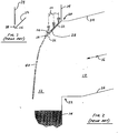
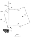
- Fig. 1 of the accompanying drawings is a schematic representation of a portion of a known wet flue gas desulfurization (FGD) system 10, wherein a wet scrubber module 12 having a cylindrical housing 14 receives a flue gas 16 at a transition between an inlet flue 18 and the housing.
- the inlet flue 18 typically approaches the cylindrical housing 14 at a downward angle ranging from 0° to 90° from the horizontal.
- the inlet flue 18 is typically rectangular in cross-section, having a width W that is approximately 2.5 times greater than its height H (i.e., an aspect ratio of width to height W/H of approximately 2.5).
- the inlet flue 18 is mitered so that it intersects and attaches to the cylindrical housing 14 at a 90° angle, i.e., the inlet flue 18 is substantially perpendicular to the cylindrical housing 14. This perpendicular orientation simplifies the transition, structural design and fabrication of the wet scrubber module 12.
- other portions (not shown) of the flue system upstream of the inlet flue 18 may include cross-section transitions, elbows, fans, and/or other hydraulic devices to supply the flue gas 16 to the inlet flue 18.
- an inlet awning 28 is used to direct part of the hot flue gas 16, typically provided to the wet scrubber module 12 at a temperature of approximately 150°C (300°F), downwardly at a 45° angle with respect to horizontal.
- Liquid slurry 30 that is sprayed within the wet scrubber module 12 and/or which drains from packing, trays, or other surfaces within the wet scrubber module 12, flows downwardly onto an upper surface 32 of the inlet awning 28.
- a weir plate 34 located above a tip 36 of the inlet awning 28 provides a gap 38 through which liquid slurry 30 passes, and thus regulates and improves the uniformity of a liquid slurry curtain 40 that is discharged down into the hot flue gas stream 16.
- the hot flue gas 16 enters the wet scrubber module 12, it is quenched and humidified by the liquid slurry curtain 40, evaporating a fraction of the water present in the liquid slurry curtain 40.
- sidewalls 44 extend from the inlet awning 28 into the housing 14 and downwardly to a point below the lower surface 26 of the inlet flue 18. These sidewalls 44 prevent liquid slurry 30 from flowing off the side ends 42 of the inlet awning 28 or along an inner surface 46 of the housing 14 from entering the inlet flue 18. These sidewalls 44 are necessary to maintain an acceptable wet/dry interface away from these surfaces to avoid the deposition problems discussed earlier.
- the inlet awning 28 is provided with stiffeners 48 which, in conjunction with the sidewalls 44, further distribute the slurry flow 30 evenly about these surfaces.
- the present invention provides a device for deflecting a liquid slurry flow in a housing away from an inlet flue for conveying hot flue gas to the housing, the device having an upper surface and communicating with the housing at an inner wall of the housing, the device comprising: an inlet awning having a bottom portion horizontally extending into the housing from an upper surface of the inlet flue, and an inclined top portion connected to the bottom portion and the inner wall of the housing, the top portion extending upwardly at an incline from the bottom portion to the inner wall of the housing, the top portion having sufficient area to collect liquid slurry in excess of that required to achieve instant cooling and humidification of the hot flue gas, the top and bottom portions forming a tip at an area where the top portion is connected to the bottom portion; and an extension extending outwardly from the tip of the inlet awning and slightly below the bottom portion of the inlet awning in order to deflect the liquid slurry flow away from the bottom portion of the inlet awning to keep the bottom portion dry.
- a preferred embodiment of the present invention provides a solution to the aforementioned problems by means of a construction which reduces the flue gas side pressure drop at a transition of an inlet flue which conveys hot flue gas and a wet FGD scrubber module which receives the hot flue gas, while still providing for minimized deposition of slurry deposits at the transition.
- a first embodiment of the present invention which comprises an inlet flue 19 communicating with a housing 14 of a wet scrubber module 12 for supplying hot flue gas 16 thereto.
- the inlet flue 19 has an upper surface 24 and a lower surface 26.
- An inlet awning 50 is provided having a bottom portion 52 which is connected to and which extends horizontally into the wet scrubber module 12 from the upper surface 24 of the inlet flue 19.
- the bottom portion 52 can also be an extension of the upper surface 24.
- the inlet awning 50 also has a top portion 54 connected to the bottom portion 52 at a tip 56.
- Top portion 54 is inclined upwardly towards the inner surface 46 of the housing 14 and is connected thereto.
- the top portion 54 is oriented at an inclined angle from the horizontal in order to direct the liquid slurry flow 30 towards the inner portion of the housing 14, and downwardly away from the inlet flue 19.
- the inclined top portion 54 prevents deposition and build-up of slurry solids that would normally occur on a flat surface.
- the extension of the top portion 54 into housing 14 is sized to have an area sufficient to capture an amount of falling liquid slurry flow 30 in excess of that required to achieve instant cooling of, and to completely humidify, the inlet flue gas 16 as it flows through the liquid slurry curtain 40.
- the amount of hot flue gas 16 entering the wet scrubber module 12 and the FGD chemistry process determines how much liquid slurry is needed for flue gas desulfurization.
- the degree to which the top portion 54 extends into the housing 14 depends on how much liquid flow slurry flow 30 is needed to provide cooling and humidification of the inlet flue gas 16 while preventing deposition at the inlet. Of course this requires a knowledge of the flow characteristics and distribution within the wet scrubber module 12 which would be available to those skilled in the art employing the present invention.
- the inlet awning 50 need not extend very far into the wet scrubber module 12 from the housing 14.
- the liquid slurry curtain 40 extends far enough in to the housing 14 to prevent splashing of liquid slurry back on to the lower surface 26 of the inlet flue 19 because unwanted deposition can also occur at this location.
- Suitable combinations of inlet awning 50 area and angle of inclination of the top portion 54 can thus be selected to achieve the desired results.
- the top portion 54 is inclined at an angle with respect to the horizontal within a range of approximately 20°-45°, with the preferred angle being 30°.
- the angle between a line drawn from the lower surface corner 22 and the tip 60 with respect to the vertical is within a range of approximately 10°-20°, with the preferred angle being 13°.
- the bottom portion 52 of the inlet awning 50 is exposed to dry, hot flue gas 16 next to it either by using a straight approach inlet flue 19, such as that shown in Fig. 6, or one which incorporates turning vanes 58 therein, as shown in Fig. 10.
- an awning extension 60 extends outwardly and slightly below the tip 56 of the bottom portion 52 to keep it dry.
- the awning extension 60 should extend approximately at least 25 mm (one inch) below the bottom portion 52 of the inlet awning 50.
- an optional weir plate 62 which functions as does the weir plate 34 in known designs, providing a gap 64 through which liquid slurry 30 passes, to regulate and improve the uniformity of a liquid slurry curtain 40 that is discharged down into the hot flue gas stream 16.
- Small stiffener gusset plates 48' would be employed as necessary for structural support of the weir plate 62, but would be omitted if the weir plate 62 is not required.
- Liquid slurry flow 30 that is sprayed within the wet scrubber module 12 and/or which drains from packing, trays, or other devices within the wet scrubber module 12, flows downwardly onto the top portion 54 of the inlet awning 50.
- This liquid slurry flow 30 is momentarily held back by the weir plate 62, if provided as shown in Figs. 6 and 7, such that the liquid slurry flow 30 is channeled through the gap 64, or it can immediately flow off of the inlet awning 50 as shown in Figs. 8 and 9 if the weir plate 62 is omitted.
- the weir plate 62 is desirable at low wet scrubber module liquid slurry fluxes that may not otherwise flow uniformly off of the inlet awning 50.
- the liquid slurry 30 flows from the inlet awning 50 and forms the thick liquid slurry curtain 40 that quenches and humidifies the hot flue gas 16 entering the wet scrubber module 12 through the inlet flue 18 or 19.
- the location of the liquid slurry curtain 40 defines the wet/dry interface which, in a wet scrubber, needs to be kept away from the inlet flue 18 or 19 and the inner surface 46 so that deposits do not form.
- sidewalls 66 extend from the sides of inlet awning 50 downwardly to a point below the lower surface 26 of inlet flue 18, and can also be employed for inlet flues 18.
- the sidewalls 66 prevent liquid slurry 30 from flowing off the sides of the inlet awning 50 or along the inner surface 46 of the wet scrubber module 12 and also serve to prevent the liquid slurry 30 from entering the inlet flue 18, or 19 to avoid the aforementioned deposition problems.
- the inlet awning 50 of the present invention increases the height H and the cross-sectional flow area between the bottom portion 52 of inlet awning 50 and the lower surface 26 of inlet flue 18 or 19. This results in reduced flue gas flow velocity and gas side pressure drop.
- Flow model testing of the present invention predicts a reduction of an inlet gas side total pressure drop of approximately 33% as compared to the previous inlet awning design at typical wet scrubber module operating conditions. Furthermore, during flow model testing of the present invention, flow visualization of the wet/dry interface proved that the bottom portion 52 of the inlet awning 50 and the upper surface 24 of the inlet flue were not wetted, thus maintaining the desired deposition-free characteristics.
Landscapes
- Engineering & Computer Science (AREA)
- Chemical & Material Sciences (AREA)
- Health & Medical Sciences (AREA)
- Biomedical Technology (AREA)
- Environmental & Geological Engineering (AREA)
- Analytical Chemistry (AREA)
- General Chemical & Material Sciences (AREA)
- Oil, Petroleum & Natural Gas (AREA)
- Chemical Kinetics & Catalysis (AREA)
- Treating Waste Gases (AREA)
- Gas Separation By Absorption (AREA)
- Treatment Of Sludge (AREA)
Applications Claiming Priority (2)
| Application Number | Priority Date | Filing Date | Title |
|---|---|---|---|
| US08/236,617 US5403523A (en) | 1994-05-02 | 1994-05-02 | Wet scrubber inlet awning with low pressure drop |
| US236617 | 1994-05-02 |
Publications (3)
| Publication Number | Publication Date |
|---|---|
| EP0681146A2 true EP0681146A2 (de) | 1995-11-08 |
| EP0681146A3 EP0681146A3 (de) | 1996-06-05 |
| EP0681146B1 EP0681146B1 (de) | 1999-11-17 |
Family
ID=22890255
Family Applications (1)
| Application Number | Title | Priority Date | Filing Date |
|---|---|---|---|
| EP95302968A Expired - Lifetime EP0681146B1 (de) | 1994-05-02 | 1995-05-01 | Vorrichtung zum Ablenken einer Strömung von flüssigem Schlamm |
Country Status (7)
| Country | Link |
|---|---|
| US (1) | US5403523A (de) |
| EP (1) | EP0681146B1 (de) |
| JP (1) | JPH0838845A (de) |
| KR (1) | KR0134992B1 (de) |
| CA (1) | CA2148315C (de) |
| DE (1) | DE69513323D1 (de) |
| ES (1) | ES2138146T3 (de) |
Families Citing this family (9)
| Publication number | Priority date | Publication date | Assignee | Title |
|---|---|---|---|---|
| US5656046A (en) * | 1996-01-16 | 1997-08-12 | The Babcock & Wilcox Company | Inlet awning for high velocity absorbers |
| US6538577B1 (en) * | 1997-09-05 | 2003-03-25 | Silver Springs Networks, Inc. | Electronic electric meter for networked meter reading |
| US6488899B1 (en) * | 1998-02-11 | 2002-12-03 | The Babcock & Wilcox Company | Low pressure drop inlet design to promote good gas flow patterns in high velocity absorbers |
| US6267358B1 (en) | 1999-06-18 | 2001-07-31 | The Babcock & Wilcox Company | Low pressure drop inlet for high velocity absorbers with straight tanks |
| US20140112834A1 (en) * | 2012-10-23 | 2014-04-24 | Babcock & Wilcox Power Generation Group, Inc. | System and method for controlling scale build-up in a wfgd |
| US9789419B2 (en) * | 2015-03-08 | 2017-10-17 | Hossein Akhavi | Restoring cooling tower outlet fog into water cycle |
| KR20190071949A (ko) | 2017-12-15 | 2019-06-25 | 이춘옥 | 천연성분을 이용한 금속표면 세정제 |
| CN111655357A (zh) * | 2018-01-30 | 2020-09-11 | 三菱日立电力系统株式会社 | 脱硫系统 |
| CN111760431B (zh) * | 2020-06-11 | 2025-06-17 | 浙江菲达环保科技股份有限公司 | 一种湿法脱硫喷淋塔节能装置 |
Family Cites Families (9)
| Publication number | Priority date | Publication date | Assignee | Title |
|---|---|---|---|---|
| US1172930A (en) * | 1915-12-08 | 1916-02-22 | Hermann A Brassert | Method of and apparatus for gas-washing. |
| US1564075A (en) * | 1925-01-30 | 1925-12-01 | Lakin Mfg Company | Water recooler |
| US2265227A (en) * | 1939-06-28 | 1941-12-09 | Whiting Corp | Stack for furnaces |
| US2603464A (en) * | 1945-01-25 | 1952-07-15 | Fluor Corp | Recovery of elemental sulfur |
| FR2203967B1 (de) * | 1972-10-19 | 1975-09-12 | Ind Chauffage L | |
| DE2948602C2 (de) * | 1979-12-03 | 1984-10-31 | Balcke-Dürr AG, 4030 Ratingen | Vorrichtung zur Geräuschdämpfung in Kühltürmen |
| FR2542070B1 (fr) * | 1983-03-02 | 1989-05-19 | Laurent Francois | Installation et procede de chauffage du type a combustion submergee |
| DE8608453U1 (de) * | 1986-03-27 | 1993-07-22 | Uhde Gmbh, 4600 Dortmund | Vorrichtung zur Reinigung von Gasströmen |
| US5281402A (en) * | 1993-01-27 | 1994-01-25 | The Babcock & Wilcox Company | Cost reduction of wet FGD system with a tray |
-
1994
- 1994-05-02 US US08/236,617 patent/US5403523A/en not_active Expired - Lifetime
-
1995
- 1995-04-25 KR KR1019950009698A patent/KR0134992B1/ko not_active Expired - Lifetime
- 1995-04-27 JP JP7125574A patent/JPH0838845A/ja not_active Withdrawn
- 1995-05-01 ES ES95302968T patent/ES2138146T3/es not_active Expired - Lifetime
- 1995-05-01 DE DE69513323T patent/DE69513323D1/de not_active Expired - Lifetime
- 1995-05-01 EP EP95302968A patent/EP0681146B1/de not_active Expired - Lifetime
- 1995-05-01 CA CA002148315A patent/CA2148315C/en not_active Expired - Lifetime
Also Published As
| Publication number | Publication date |
|---|---|
| JPH0838845A (ja) | 1996-02-13 |
| US5403523A (en) | 1995-04-04 |
| CA2148315C (en) | 1998-10-27 |
| EP0681146A3 (de) | 1996-06-05 |
| KR950033248A (ko) | 1995-12-22 |
| DE69513323D1 (de) | 1999-12-23 |
| ES2138146T3 (es) | 2000-01-01 |
| EP0681146B1 (de) | 1999-11-17 |
| CA2148315A1 (en) | 1995-11-03 |
| KR0134992B1 (ko) | 1998-04-21 |
Similar Documents
| Publication | Publication Date | Title |
|---|---|---|
| CA1157767A (en) | Wet separator | |
| KR0179232B1 (ko) | 연도 가스 탈황 습식 세척기용 스프레이 헤더 | |
| US4919696A (en) | Supercooling type mist eliminator apparatus | |
| US4582515A (en) | Wet separator for and method of purifying polluted conditioning air | |
| US5558818A (en) | Wet flue gas scrubber having an evenly distributed flue gas inlet | |
| EP0681146B1 (de) | Vorrichtung zum Ablenken einer Strömung von flüssigem Schlamm | |
| EP0613994B1 (de) | System zum Absaugen von Staub in Tunneln | |
| JPH01270960A (ja) | 遠心分離型塗料ミスト含有気体浄化装置 | |
| EP1252373B1 (de) | Ein verfahren und vorrichtung zum betreiben einer elektrolytischen zelle | |
| EP0640373B1 (de) | Sprühturm und Verfahren zur Kühlung, Befeuchtung und/oder Reinigung von Gas | |
| US5569415A (en) | Cross-flow cooling tower with reduced upper inboard fill section | |
| US5791404A (en) | Flooding reduction on a tubular heat exchanger | |
| US20140112834A1 (en) | System and method for controlling scale build-up in a wfgd | |
| US3726064A (en) | Scrubbing apparatus for polluted gases | |
| DE4238595A1 (de) | Modulare Lüftungseinheit mit integriertem Ventilator und angeschlossenem Filterrahmen, insbesondere für reinraumtechnische Zwecke | |
| JP2003103139A (ja) | 湿式排煙脱硫装置 | |
| JP3167837B2 (ja) | ガス冷却室及びガス冷却室を備えた廃棄物処理装置 | |
| CN216726640U (zh) | 一种用于脱硫脱硝的多层抽屉式固定床 | |
| JPH0978147A (ja) | 焼結鉱の冷却方法及び冷却装置 | |
| JP2765914B2 (ja) | 加湿装置 | |
| US4846858A (en) | Apparatus for evaporating a liquid in a gas stream | |
| JP2002219323A (ja) | ガス減温塔 | |
| RU2724780C1 (ru) | Устройство для мокрой очистки газов | |
| RU2061529C1 (ru) | Мокрый искрогаситель | |
| JP2002228366A (ja) | 燃焼炉一体型ガス冷却塔 |
Legal Events
| Date | Code | Title | Description |
|---|---|---|---|
| PUAI | Public reference made under article 153(3) epc to a published international application that has entered the european phase |
Free format text: ORIGINAL CODE: 0009012 |
|
| AK | Designated contracting states |
Kind code of ref document: A2 Designated state(s): DE ES FR GB IT SE |
|
| PUAL | Search report despatched |
Free format text: ORIGINAL CODE: 0009013 |
|
| AK | Designated contracting states |
Kind code of ref document: A3 Designated state(s): DE ES FR GB IT SE |
|
| 17P | Request for examination filed |
Effective date: 19960906 |
|
| 17Q | First examination report despatched |
Effective date: 19980304 |
|
| GRAG | Despatch of communication of intention to grant |
Free format text: ORIGINAL CODE: EPIDOS AGRA |
|
| GRAG | Despatch of communication of intention to grant |
Free format text: ORIGINAL CODE: EPIDOS AGRA |
|
| GRAH | Despatch of communication of intention to grant a patent |
Free format text: ORIGINAL CODE: EPIDOS IGRA |
|
| RAP1 | Party data changed (applicant data changed or rights of an application transferred) |
Owner name: MCDERMOTT TECHNOLOGY, INC. |
|
| GRAH | Despatch of communication of intention to grant a patent |
Free format text: ORIGINAL CODE: EPIDOS IGRA |
|
| GRAA | (expected) grant |
Free format text: ORIGINAL CODE: 0009210 |
|
| AK | Designated contracting states |
Kind code of ref document: B1 Designated state(s): DE ES FR GB IT SE |
|
| PG25 | Lapsed in a contracting state [announced via postgrant information from national office to epo] |
Ref country code: SE Free format text: THE PATENT HAS BEEN ANNULLED BY A DECISION OF A NATIONAL AUTHORITY Effective date: 19991117 Ref country code: IT Free format text: LAPSE BECAUSE OF FAILURE TO SUBMIT A TRANSLATION OF THE DESCRIPTION OR TO PAY THE FEE WITHIN THE PRE;WARNING: LAPSES OF ITALIAN PATENTS WITH EFFECTIVE DATE BEFORE 2007 MAY HAVE OCCURRED AT ANY TIME BEFORE 2007. THE CORRECT EFFECTIVE DATE MAY BE DIFFERENT FROM THE ONE RECORDED.SCRIBED TIME-LIMIT Effective date: 19991117 Ref country code: FR Free format text: LAPSE BECAUSE OF FAILURE TO SUBMIT A TRANSLATION OF THE DESCRIPTION OR TO PAY THE FEE WITHIN THE PRESCRIBED TIME-LIMIT Effective date: 19991117 |
|
| REF | Corresponds to: |
Ref document number: 69513323 Country of ref document: DE Date of ref document: 19991223 |
|
| REG | Reference to a national code |
Ref country code: ES Ref legal event code: FG2A Ref document number: 2138146 Country of ref document: ES Kind code of ref document: T3 |
|
| PG25 | Lapsed in a contracting state [announced via postgrant information from national office to epo] |
Ref country code: DE Free format text: LAPSE BECAUSE OF FAILURE TO SUBMIT A TRANSLATION OF THE DESCRIPTION OR TO PAY THE FEE WITHIN THE PRESCRIBED TIME-LIMIT Effective date: 20000218 |
|
| EN | Fr: translation not filed | ||
| PLBE | No opposition filed within time limit |
Free format text: ORIGINAL CODE: 0009261 |
|
| STAA | Information on the status of an ep patent application or granted ep patent |
Free format text: STATUS: NO OPPOSITION FILED WITHIN TIME LIMIT |
|
| 26N | No opposition filed | ||
| PGFP | Annual fee paid to national office [announced via postgrant information from national office to epo] |
Ref country code: ES Payment date: 20010608 Year of fee payment: 7 |
|
| REG | Reference to a national code |
Ref country code: GB Ref legal event code: IF02 |
|
| PG25 | Lapsed in a contracting state [announced via postgrant information from national office to epo] |
Ref country code: ES Free format text: LAPSE BECAUSE OF NON-PAYMENT OF DUE FEES Effective date: 20020502 |
|
| REG | Reference to a national code |
Ref country code: ES Ref legal event code: FD2A Effective date: 20030611 |
|
| PGFP | Annual fee paid to national office [announced via postgrant information from national office to epo] |
Ref country code: GB Payment date: 20060525 Year of fee payment: 12 |
|
| GBPC | Gb: european patent ceased through non-payment of renewal fee |
Effective date: 20070501 |
|
| PG25 | Lapsed in a contracting state [announced via postgrant information from national office to epo] |
Ref country code: GB Free format text: LAPSE BECAUSE OF NON-PAYMENT OF DUE FEES Effective date: 20070501 |