EP0681299B1 - Verfahren zur Befestigung eines Abstandhalters auf einem Wasserstab geradlinigen Querschnitts - Google Patents
Verfahren zur Befestigung eines Abstandhalters auf einem Wasserstab geradlinigen Querschnitts Download PDFInfo
- Publication number
- EP0681299B1 EP0681299B1 EP94303212A EP94303212A EP0681299B1 EP 0681299 B1 EP0681299 B1 EP 0681299B1 EP 94303212 A EP94303212 A EP 94303212A EP 94303212 A EP94303212 A EP 94303212A EP 0681299 B1 EP0681299 B1 EP 0681299B1
- Authority
- EP
- European Patent Office
- Prior art keywords
- water rod
- spacer
- band
- water
- over center
- Prior art date
- Legal status (The legal status is an assumption and is not a legal conclusion. Google has not performed a legal analysis and makes no representation as to the accuracy of the status listed.)
- Expired - Lifetime
Links
- XLYOFNOQVPJJNP-UHFFFAOYSA-N water Substances O XLYOFNOQVPJJNP-UHFFFAOYSA-N 0.000 title claims description 99
- 125000006850 spacer group Chemical group 0.000 title claims description 50
- 238000000034 method Methods 0.000 title description 2
- 239000000446 fuel Substances 0.000 claims description 40
- 230000013011 mating Effects 0.000 claims description 2
- 238000009835 boiling Methods 0.000 description 6
- 239000003758 nuclear fuel Substances 0.000 description 5
- 238000010276 construction Methods 0.000 description 3
- 239000012223 aqueous fraction Substances 0.000 description 1
- 230000002950 deficient Effects 0.000 description 1
- 229910001026 inconel Inorganic materials 0.000 description 1
- 238000003780 insertion Methods 0.000 description 1
- 230000037431 insertion Effects 0.000 description 1
- 238000004519 manufacturing process Methods 0.000 description 1
- 239000011159 matrix material Substances 0.000 description 1
- 230000000149 penetrating effect Effects 0.000 description 1
Images


Classifications
-
- G—PHYSICS
- G21—NUCLEAR PHYSICS; NUCLEAR ENGINEERING
- G21C—NUCLEAR REACTORS
- G21C3/00—Reactor fuel elements and their assemblies; Selection of substances for use as reactor fuel elements
- G21C3/30—Assemblies of a number of fuel elements in the form of a rigid unit
- G21C3/32—Bundles of parallel pin-, rod-, or tube-shaped fuel elements
- G21C3/33—Supporting or hanging of elements in the bundle; Means forming part of the bundle for inserting it into, or removing it from, the core; Means for coupling adjacent bundles
- G21C3/332—Supports for spacer grids
-
- Y—GENERAL TAGGING OF NEW TECHNOLOGICAL DEVELOPMENTS; GENERAL TAGGING OF CROSS-SECTIONAL TECHNOLOGIES SPANNING OVER SEVERAL SECTIONS OF THE IPC; TECHNICAL SUBJECTS COVERED BY FORMER USPC CROSS-REFERENCE ART COLLECTIONS [XRACs] AND DIGESTS
- Y02—TECHNOLOGIES OR APPLICATIONS FOR MITIGATION OR ADAPTATION AGAINST CLIMATE CHANGE
- Y02E—REDUCTION OF GREENHOUSE GAS [GHG] EMISSIONS, RELATED TO ENERGY GENERATION, TRANSMISSION OR DISTRIBUTION
- Y02E30/00—Energy generation of nuclear origin
- Y02E30/30—Nuclear fission reactors
Definitions
- This invention relates to the fabrication of nuclear fuel bundles for boiling water nuclear reactors. More particularly, in a nuclear fuel bundle having a rectilinear sectioned water rod -- preferably square -- an inside band and spring for a spacer are disclosed which enable the spacer to firmly attach to the water rod. Assembly of the fuel bundle can easily follow from the disclosed attachment of the water rod and spacers.
- Nuclear fuel bundles for boiling water nuclear reactors typically include a lower tie plate for supporting a matrix of upstanding fuel rods of the bundle and for admitting water.
- An upper tie plate is secured to the other end of the fuel rods and enables the water and generated steam to exit the fuel bundle. Since the fuel rods are long and slender, they must be braced intermittently with respect to the tie plates. This being the case, normally seven so-called spacers are placed between the upper and lower tie plates. These spacers individually surround each fuel rod at the elevation of each spacer to prevent the fuel rods from abrading contact during the generation of steam and to maintain the design clearances between the fuel rods during bundle operation.
- fuel bundles typically include large, central water rods. These water rods exceed by many times the diameter of the fuel rods and have for their main purpose the introduction of moderating water into the upper two phase region of the fuel bundle.
- the upper portion of a fuel bundle in a boiling water reactor has the steam fraction present in the fuel bundle predominate over the water fraction. This excess of steam renders the nuclear performance of the upper portion of the fuel bundle in a boiling water reactor deficient; more moderating water is needed in the upper two phase region of the fuel bundle for efficient nuclear performance.
- the spacers are first attached to the large water rods and registered at their respective water rod surrounding apertures to form a "tree" configuration. Thereafter, the individual fuel rods are threaded through the spacers at each successive fuel rod surrounding aperture to and towards one of the tie plates. The threaded rods pass successively through each rod aperture in each successive spacer until all such fuel rods are held firmly in place. Once all the fuel rods are in place, the remaining tie plate is attached and the fuel assembly -- consisting of the tie plates, large central water rod, spacers, and fuel rods is ready for placement into the fuel channel.
- Large central water rods are usually circular in cross-section; in the case under consideration here, the large central water rods are rectilinear in section -- preferably square in cross-section.
- a fuel bundle having:
- a rectilinear sectioned water rod preferably of square cross-section -- is provided with horizontal grooves for keying to bands on the inner, water rod surrounding band of spacers.
- These horizontal grooves are vertically spaced on the water rod at the intended elevation of the respective spacers for keying to an over center spring on each spacer.
- these vertically spaced grooves do not extend fully through the water rod.
- Each spacer is constructed preferably of Inconel and includes a specialized inner band with an over center spring for keying to the water rod at the horizontal grooves.
- the inner spacer member includes an upper water rod surrounding band, a lower water rod surrounding band, and four connecting vertical members -- one positioned at each of the four comers of the rectilinear sectioned water rod.
- Two adjacent vertical members are each bent inward to each form paired vertically spaced apart stops. These two adjacent vertical members thus each contact one side of the water rod at a total of four spaced apart stops. These four spaced apart stops -- with two stops on each vertical member -bear on the comers of one side of the water rod to maintain the water rod surrounding band of the spacer plumb with respect to the water rod.
- the remaining two adjacent vertical members are bent inward to form biasing springs in contact the two remaining comers at single points.
- An over center spring member extends between two of the vertical members -- preferably those two members having the four stops configured thereon.
- This spring has two stable positions; in the first position it is bent away from the water rod, and in the second position it is bent towards the water rod.
- the over center spring Prior to and during insertion of the water rod, the over center spring is in its first position, deflected away from the water rod.
- the spring When the spacer is located with the spring overlying its respective horizontal locating groove, the spring is manually tipped from its first position to its second position to contact the water rod and lodge within the horizontal groove. There results a firm attachment of the spacer to the water rod, permitting the remainder of the assembly of the fuel bundle to readily proceed.
- a rectilinear sectioned water rod W - here shown square in section -- is shown having seven spacers S 1 - S 7 keyed to water rod W.
- Lower tie plate L is shown fastened to the bottom of the assembly. As all spacers are in place, a single fuel rod R is shown being threaded into place.
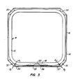
- Fig. 2 is a section taken at the top of a spacer S.
- Water rod W is shown having a wall thickness 10 with band 14 surrounding the water rod.
- a typical spacer cell 12 is illustrated, the reader understanding that much of the spacer has been omitted. The method of locking is not shown in this view.
- Fig. 3 is a section similar to Fig. 2 with the section being taken just above a locking groove 18 only partially penetrating the thickness 10 of water rod W.
- legs 30 appear at the upper portion of the figure; these legs spring bias the spacer band -- and hence the spacer -- into a right angle with respect to water rod W.
- legs 32 appear at the lower portion of the figure; these legs contact the corners of water rod W, maintain band 14 at a right angle around the water rod W, and form the holding member for over center spring 20.
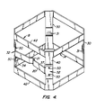
- Fig. 4 shows an isometric view of the band surrounding the water rod comprising upper and lower band members 42.
- the water rod is not shown.
- Vertical legs 30 act as springs which contact the water rod at dimples 31 and bias the water rod toward stops 50 on vertical legs 32.
- the over center spring 20 extends between vertical legs 32.
- the over center spring 20 has an inwardly projecting central region 21 which fits into the locking groove 18, shown in Fig. 3 and Fig. 5.
- Fig. 5A is an elevation view showing spring 20 in front of the locking groove 18.
- Fig. 5B shows a top view in section at the locking groove. The spring is shown in the locked position 60 and in the unlocked position 52.
- Each of the two positions 60 and 52 is a stable position. A moderate applied force will cause the spring to snap from one position to the other.
Landscapes
- Physics & Mathematics (AREA)
- Engineering & Computer Science (AREA)
- Plasma & Fusion (AREA)
- General Engineering & Computer Science (AREA)
- High Energy & Nuclear Physics (AREA)
- Monitoring And Testing Of Nuclear Reactors (AREA)
- Sewage (AREA)
- Springs (AREA)
Claims (4)
- Brennstoffbündel enthaltend:obere und untere (L) Ankerplatten,mehrere aufrecht stehende Brennstoffstäbe (R), die zwischen den Ankerplatten gehalten sind,wenigstens einen zentralen großen Wasserstab (W), der sich wenigstens teilweise zwischen den Ankerplatten erstreckt, undmehrere Abstandshalter (S), die um den großen zentralen Wasserstab (W) herum angebracht sind,Mittel zum Festkeilen der Abstandshalter (S) an dem großen zentralen Wasserstab (W) enthaltend in Kombination:eine Vertiefung (18), die in dem großen zentralen Wasserstab (W) an einer Höhe auf dem Wasserstab (W) ausgebildet ist, damit der Abstandshalter den Wasserstab (W) verkeilen kann,ein inneres Band (14), das an dem Abstandshalter (S) befestigt ist und den Wasserstab (W) umgibt, wobei das innere Band (14) Anschlagmittel aufweist, die an dem Wasserstab (W) angreifen, gekennzeichnet durcheine an dem Band befestigte Schnappfeder (20), die eine erste über die Mitte vorgespannte Stellung (52) entfernt von dem Wasserstab (W) und eine zweite über die Mitte vorgespannte Stellung (60) in Kontakt mit dem Wasserstab (W) aufweist, undwobei die Feder (20) und die Vertiefung (18) für einen gemeinsamen Paßeingriff geformt sind, um den Abstandshalter (S) an dem inneren Band (14) an dem Wasserstab (W) befestigt zu halten durch Eingriff der Feder (20) mit der Vertiefung (18).
- Brennstoffbündel nach Anspruch 1, wobei der Wasserstab (W) eine rechtwinklige Querschnittsform hat und vier Ecken bildet und wobei das innere Band (14) von dem Abstandshalter (S) enthält:ein oberes Bandteil, das den Wasserstab umgibt, ein unteres Bandteil, das den Wasserstab umgibt, vier vertikale Schenkelteile (30,32), die an den Ecken von dem Wasserstab angeordnet sind,wobei die Anschlagmittel auf jedem von zwei benachbarten vertikalen Schenkelteilen (32) zwei Anschläge (50) aufweisen, um vier Kontaktpunkte mit zwei Ecken von dem zentralen Wasserstab (W) zu bilden,wobei die Anschlagmittel ferner auf jedem von zwei verbleibenden benachbarten vertikalen Schenkelteilen (30), die zur Bildung von Federn gebogen sind, einen einzelnen Anschlag (31) aufweisen zum Vorspannen des Bandes in Kontakt mit den übrigen zwei Ecken von dem zentralen Wasserstab (W).
- Brennstoffbündel nach Anspruch 2, wobei die Schnappfeder (20) zwischen zwei der vertikalen Schenkelteile (32) verbunden ist.
- Brennstoffbündel nach Anspruch 2, wobei die Schnappfeder (20) zwischen zwei der vertikalen Schenkelteile (32) verbunden ist, die jeweils die zwei Anschläge (50) aufweisen.
Priority Applications (3)
| Application Number | Priority Date | Filing Date | Title |
|---|---|---|---|
| DE69420391T DE69420391T2 (de) | 1994-05-04 | 1994-05-04 | Verfahren zur Befestigung eines Abstandhalters auf einem Wasserstab geradlinigen Querschnitts |
| EP94303212A EP0681299B1 (de) | 1994-05-04 | 1994-05-04 | Verfahren zur Befestigung eines Abstandhalters auf einem Wasserstab geradlinigen Querschnitts |
| ES94303212T ES2136164T3 (es) | 1994-05-04 | 1994-05-04 | Procedimiento de fijacion de separadores para barras de agua de seccion rectilinea. |
Applications Claiming Priority (1)
| Application Number | Priority Date | Filing Date | Title |
|---|---|---|---|
| EP94303212A EP0681299B1 (de) | 1994-05-04 | 1994-05-04 | Verfahren zur Befestigung eines Abstandhalters auf einem Wasserstab geradlinigen Querschnitts |
Publications (2)
| Publication Number | Publication Date |
|---|---|
| EP0681299A1 EP0681299A1 (de) | 1995-11-08 |
| EP0681299B1 true EP0681299B1 (de) | 1999-09-01 |
Family
ID=8217691
Family Applications (1)
| Application Number | Title | Priority Date | Filing Date |
|---|---|---|---|
| EP94303212A Expired - Lifetime EP0681299B1 (de) | 1994-05-04 | 1994-05-04 | Verfahren zur Befestigung eines Abstandhalters auf einem Wasserstab geradlinigen Querschnitts |
Country Status (3)
| Country | Link |
|---|---|
| EP (1) | EP0681299B1 (de) |
| DE (1) | DE69420391T2 (de) |
| ES (1) | ES2136164T3 (de) |
Families Citing this family (1)
| Publication number | Priority date | Publication date | Assignee | Title |
|---|---|---|---|---|
| US5727039A (en) * | 1996-03-19 | 1998-03-10 | General Electric Company | Spacer capture mechansim for non-round water rods |
Family Cites Families (7)
| Publication number | Priority date | Publication date | Assignee | Title |
|---|---|---|---|---|
| FR2337407A1 (fr) * | 1975-12-31 | 1977-07-29 | Commissariat Energie Atomique | Assemblage combustible pour reacteur nucleaire |
| US4239597A (en) * | 1978-03-30 | 1980-12-16 | The Babcock & Wilcox Company | Nuclear fuel spacer grid |
| SE425272B (sv) * | 1981-02-03 | 1982-09-13 | Asea Atom Ab | Brenslepatron for kernreaktor |
| SE456461B (sv) * | 1987-02-06 | 1988-10-03 | Asea Atom Ab | Brenslepatron for kernreaktor |
| JP2703008B2 (ja) * | 1988-12-19 | 1998-01-26 | 株式会社日立製作所 | 燃料集合体及び燃料スペーサ |
| JPH04259892A (ja) * | 1991-02-15 | 1992-09-16 | Nuclear Fuel Ind Ltd | 沸騰水型原子炉用燃料集合体のスペーサ |
| JPH0572368A (ja) * | 1991-09-17 | 1993-03-26 | Nuclear Fuel Ind Ltd | 沸騰水型原子炉用核燃料体の燃料スぺーサ |
-
1994
- 1994-05-04 ES ES94303212T patent/ES2136164T3/es not_active Expired - Lifetime
- 1994-05-04 EP EP94303212A patent/EP0681299B1/de not_active Expired - Lifetime
- 1994-05-04 DE DE69420391T patent/DE69420391T2/de not_active Expired - Fee Related
Also Published As
| Publication number | Publication date |
|---|---|
| EP0681299A1 (de) | 1995-11-08 |
| DE69420391D1 (de) | 1999-10-07 |
| ES2136164T3 (es) | 1999-11-16 |
| DE69420391T2 (de) | 2000-05-11 |
Similar Documents
| Publication | Publication Date | Title |
|---|---|---|
| US5209899A (en) | Composite spacer with inconel grid and zircaloy band | |
| US4585616A (en) | Nuclear fuel spacer grid with improved outer straps | |
| EP0514120A1 (de) | Wirbelfahnen im Inconel Abstandshalter | |
| US4357298A (en) | Nuclear fuel assembly space arrangement | |
| CA1210164A (en) | Fuel assembly for a boiling water reactor | |
| KR100338912B1 (ko) | 원자로내에서연료봉을지지하기위한격자구조체 | |
| US5345487A (en) | Spacer capture method for rectilinear sectioned water rods | |
| US5002726A (en) | Nuclear fuel assembly spacer and loop spring with enhanced flexibility | |
| US4389369A (en) | Bi-metallic grid for a nuclear reactor fuel assembly | |
| US4585615A (en) | Nuclear fuel spacer grid with improved grid straps | |
| US4597937A (en) | Fuel spacer | |
| US4268356A (en) | Nuclear reactor fuel assembly grid | |
| US5085827A (en) | Nuclear fuel assembly spacer and loop spring with enhanced flexibility | |
| US4304635A (en) | Fuel assembly for nuclear boiling-water reactors | |
| EP0175496A1 (de) | Abstandshalterfangvorrichtung für Kernbrennstoffbündel | |
| JPH0361895A (ja) | 粒子保持フィルタを持つ原子炉の燃料集合体の下部コネクタ | |
| EP0681299B1 (de) | Verfahren zur Befestigung eines Abstandhalters auf einem Wasserstab geradlinigen Querschnitts | |
| EP0415205A1 (de) | Seitlich einsetzbarer Abstandshalter | |
| EP0797217B1 (de) | Vorrichtung zur Befestigung eines Abstandhalters auf einem Wasserrohr mit nicht-rundem Querschnitt | |
| US5133926A (en) | Extended burnup top nozzle for a nuclear fuel assembly | |
| US4624829A (en) | Nuclear fuel assembly channel spring and stop assembly and method of using same | |
| US4297171A (en) | Nuclear reactor fuel assembly | |
| EP0797216B1 (de) | Verfahren und Vorrichtung zur Befestigung eines Tragarms an ein tragendes Wasserrohr in einem Kernbrennstabbündel | |
| US6320924B1 (en) | I-Spring and associated ferrule assembly for a nuclear fuel bundle | |
| EP0347674B1 (de) | Brennelementbündel für einen Druckwasserreaktor |
Legal Events
| Date | Code | Title | Description |
|---|---|---|---|
| PUAI | Public reference made under article 153(3) epc to a published international application that has entered the european phase |
Free format text: ORIGINAL CODE: 0009012 |
|
| AK | Designated contracting states |
Kind code of ref document: A1 Designated state(s): CH DE ES LI SE |
|
| 17P | Request for examination filed |
Effective date: 19960508 |
|
| 17Q | First examination report despatched |
Effective date: 19980421 |
|
| GRAG | Despatch of communication of intention to grant |
Free format text: ORIGINAL CODE: EPIDOS AGRA |
|
| GRAG | Despatch of communication of intention to grant |
Free format text: ORIGINAL CODE: EPIDOS AGRA |
|
| GRAH | Despatch of communication of intention to grant a patent |
Free format text: ORIGINAL CODE: EPIDOS IGRA |
|
| GRAH | Despatch of communication of intention to grant a patent |
Free format text: ORIGINAL CODE: EPIDOS IGRA |
|
| GRAH | Despatch of communication of intention to grant a patent |
Free format text: ORIGINAL CODE: EPIDOS IGRA |
|
| GRAA | (expected) grant |
Free format text: ORIGINAL CODE: 0009210 |
|
| AK | Designated contracting states |
Kind code of ref document: B1 Designated state(s): CH DE ES LI SE |
|
| PG25 | Lapsed in a contracting state [announced via postgrant information from national office to epo] |
Ref country code: LI Free format text: LAPSE BECAUSE OF FAILURE TO SUBMIT A TRANSLATION OF THE DESCRIPTION OR TO PAY THE FEE WITHIN THE PRESCRIBED TIME-LIMIT Effective date: 19990901 Ref country code: CH Free format text: LAPSE BECAUSE OF FAILURE TO SUBMIT A TRANSLATION OF THE DESCRIPTION OR TO PAY THE FEE WITHIN THE PRESCRIBED TIME-LIMIT Effective date: 19990901 |
|
| REG | Reference to a national code |
Ref country code: CH Ref legal event code: EP |
|
| REF | Corresponds to: |
Ref document number: 69420391 Country of ref document: DE Date of ref document: 19991007 |
|
| REG | Reference to a national code |
Ref country code: ES Ref legal event code: FG2A Ref document number: 2136164 Country of ref document: ES Kind code of ref document: T3 |
|
| REG | Reference to a national code |
Ref country code: CH Ref legal event code: PL |
|
| PLBE | No opposition filed within time limit |
Free format text: ORIGINAL CODE: 0009261 |
|
| STAA | Information on the status of an ep patent application or granted ep patent |
Free format text: STATUS: NO OPPOSITION FILED WITHIN TIME LIMIT |
|
| 26N | No opposition filed | ||
| PGFP | Annual fee paid to national office [announced via postgrant information from national office to epo] |
Ref country code: SE Payment date: 20020418 Year of fee payment: 9 |
|
| PGFP | Annual fee paid to national office [announced via postgrant information from national office to epo] |
Ref country code: DE Payment date: 20020520 Year of fee payment: 9 |
|
| PGFP | Annual fee paid to national office [announced via postgrant information from national office to epo] |
Ref country code: ES Payment date: 20020606 Year of fee payment: 9 |
|
| PG25 | Lapsed in a contracting state [announced via postgrant information from national office to epo] |
Ref country code: SE Free format text: LAPSE BECAUSE OF NON-PAYMENT OF DUE FEES Effective date: 20030505 Ref country code: ES Free format text: LAPSE BECAUSE OF NON-PAYMENT OF DUE FEES Effective date: 20030505 |
|
| PG25 | Lapsed in a contracting state [announced via postgrant information from national office to epo] |
Ref country code: DE Free format text: LAPSE BECAUSE OF NON-PAYMENT OF DUE FEES Effective date: 20031202 |
|
| EUG | Se: european patent has lapsed | ||
| REG | Reference to a national code |
Ref country code: ES Ref legal event code: FD2A Effective date: 20030505 |